Home security is an increasing concern as crime rates continue to rise around
the world. The smart lock market is projected to grow to over 2.7 billion by
2023 across various applications including residential, commercial and
industrial. To keep up with this growth, startups and established companies
need a way to streamline their design process and find an inexpensive,
versatile and easy to use development solution to take a proof of concept into
production as quickly as possible. By saving time developing a prototype,
developers can spend more time incorporating key differentiating factors into
designs that maximize revenue.
Solution
To accelerate the design of IoT devices, NXP has introduced the
Rapid IoT prototyping kit. It integrates eleven NXP® devices (microcontroller,
low-power connectivity, sensors, NFC, secure element, power management,
interface) in a small form-factor hardware design and combines it with proven
software enablement (drivers, RTOS, middleware, cloud connect) and a web IDE
with GUI based programming. Refer to Figure 1 for the complete block diagram.
Rapid IoT provides the easiest path for anyone to take their connected device
to a proof-of-concept by simplifying the design process. It eliminates the
need to write code and integrates all the necessary functions required by an
IoT device including the ability to sense, think and act.
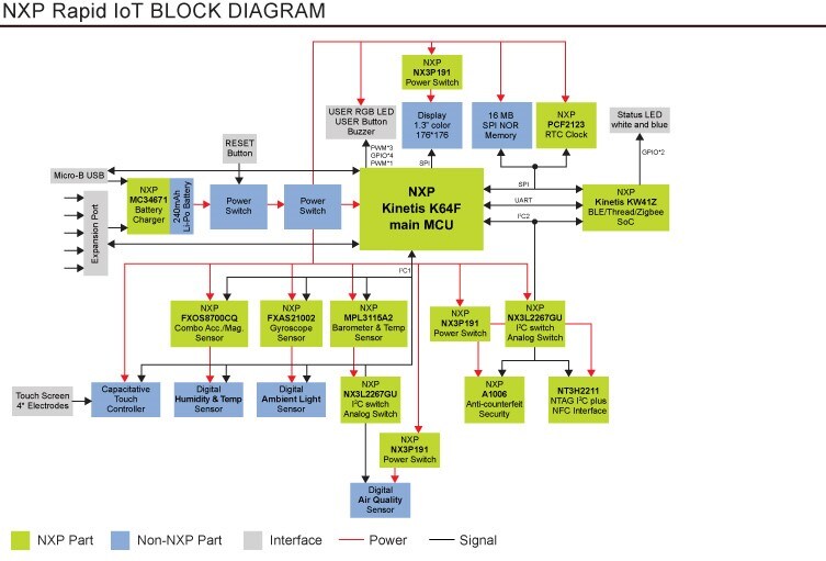
Figure 1. Rapid IoT Prototyping Kit Block Diagram
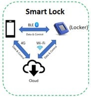
Figure 2. Smart Lock Design with Rapid IoT
Design Considerations and Implementation
Figure 2 shows the smart lock control unit conceptual design. With a smartphone app, the user can lock and unlock a door via Bluetooth Low Energy communication. If
movement is detected by the smart lock control unit, a warning message is sent
to the smartphone device and an alarm is activated. For data storage and
enhanced communication capability, the smartphone device and/or smart lock
control unit should be able to transmit/receive data from the cloud via Wi-Fi
or 4G connectivity.
To design this smart lock control unit using the Rapid IoT kit, the following
criteria was considered:
-
The control unit or locker should have a UI to locally manage and control
the lock.
-
The smart device should have a UI to wirelessly manage and control the lock
via Bluetooth Low Energy or Wi-Fi.
-
Data processed and acquired can be uploaded securely to the cloud for future
analysis.
Results
To achieve this, the Rapid IoT design uses one GPIO pin to control the locker
and uses the accelerometer to detect door movement. Wireless connectivity is
possible via Bluetooth Low Energy or Wi-Fi while the hardware and smartphone UI was easily
designed using the Rapid IoT Studio IDE tool without writing a single line of
code. To secure data uploads to the cloud, a secure tamper resistant
authentication device is used.
Figures 3 through 5 show the Rapid IoT studio environment and the smart lock
function design and hardware. Figures 6 shows the Rapid IoT smartphone UI
design which is used to wirelessly monitor and control the locker.
All the necessary files to build and test this design can be found in
this NXP community thread.
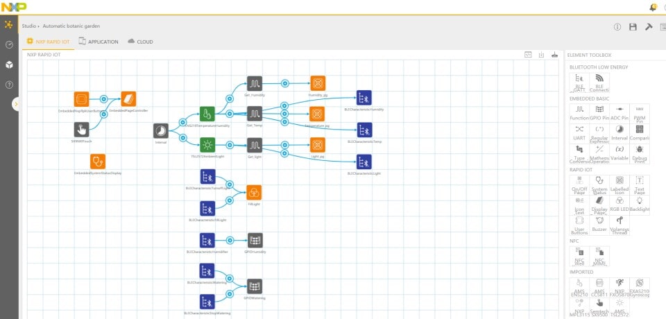
Figure 3. Rapid IoT Studio – Function Design
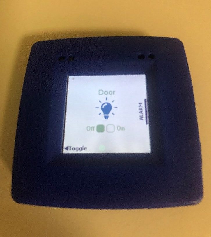
Figure 4. Rapid IoT Kit Hardware – Locker UI
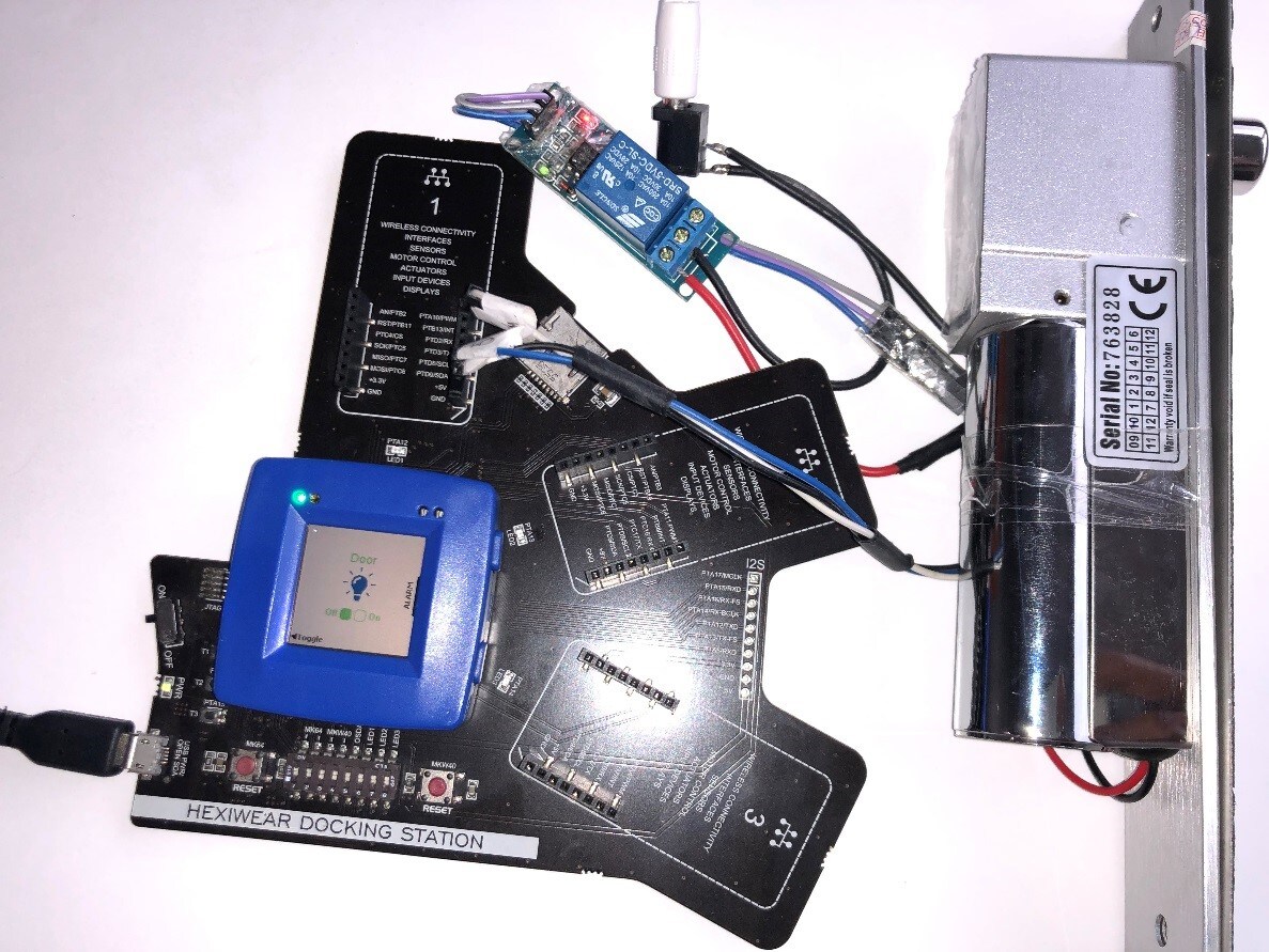
Figure 5. Rapid IoT Kit Hardware – Complete setup
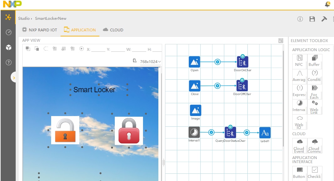
Figure 6. Rapid IoT Studio –Smart Phone UI Design
Need Help?
If you have a question or concern, you can
post it in our
Rapid IoT community
page.
Additional Resources

