Getting Started with the MPC5775B BMC + MC33771 BCC high-voltage BMS system
Contents of this document
-
Get Software
-
Plug It In
-
Build, Load
Sign in to save your progress. Don't have an account? Create one.
Purchase your MPC5775B and MC33771 high-voltage BMS Evaluation System
1. Get Software
1.1 Get Started With the MPC5775B/E-EVB
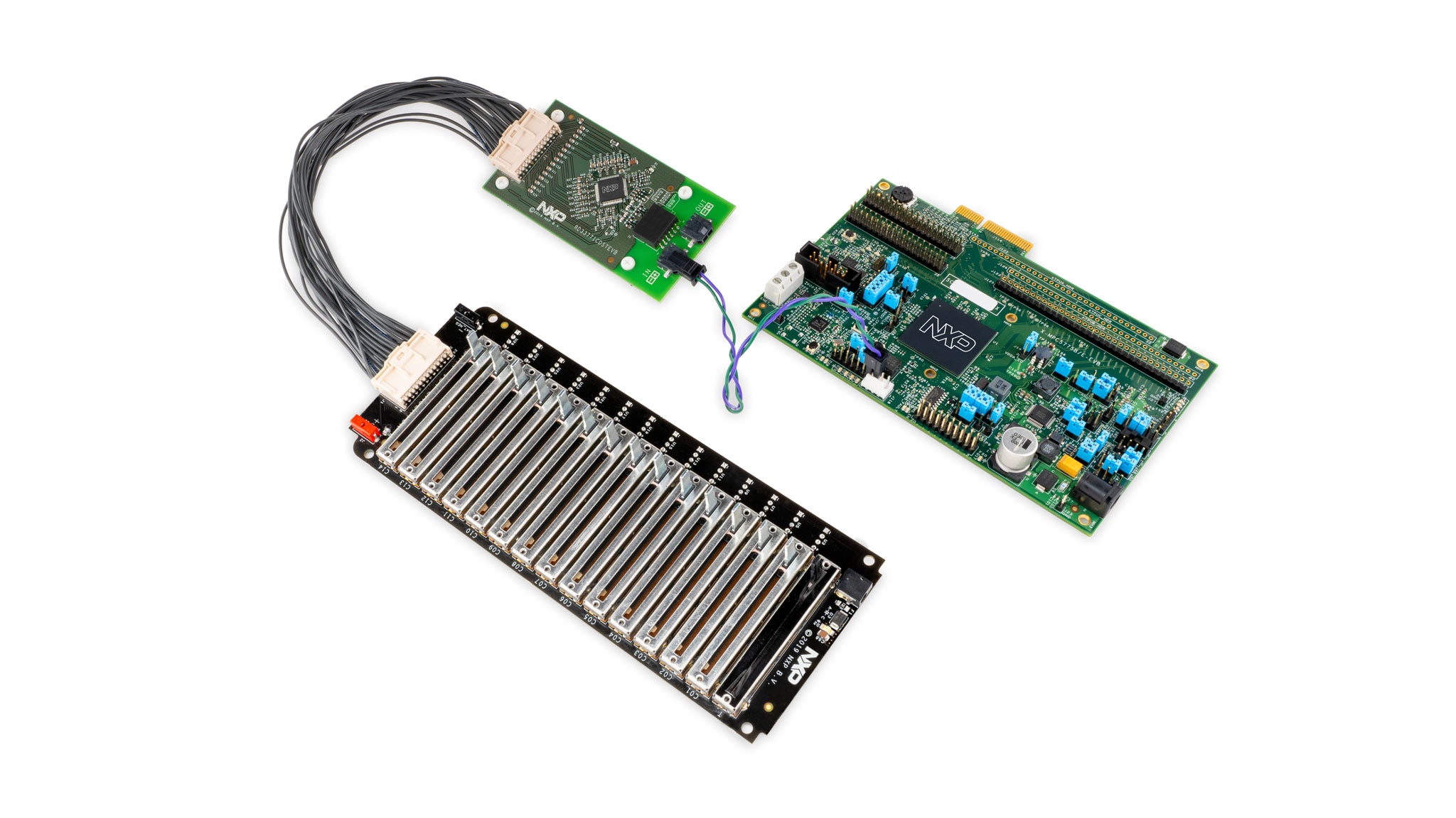
Let's take your MPC5775B battery management controller (BMC) plus MC33771 battery cell controller (BCC) high-voltage (HV) battery management system (BMS) for a test drive!
1.2 Download the MPC5775B-BatterySystem_SDK
Jump-start demo software for the MPC5775B-EVB using S32SDK 3.0.0 with FreeRTOS based on the S32 Design Studio IDE
1.3 Download the MPC5775B-BatterySystem_GUI
Graphic User Interface (GUI) software to monitor battery status using the CAN interface
1.4 Get Your Integrated Development Environment (IDE)
The MPC5775B BMC + MC33771 BCC HV BMS system performs better when using S32 Design Studio for Power Architecture® IDE
2. Plug It In
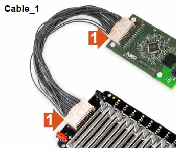
2.1 Connect BATT-14CEMULATOR and RD33771CDSTEVB
Connect the BATT-14CEMULATOR battery cell emulator board and the RDCV33771C cell controller board using Cable_1.
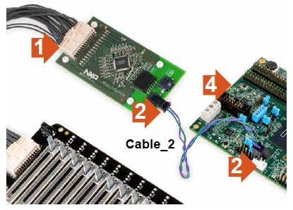
2.2 Connect RD33771CDSTEVB and MPC5775B-EVB
Connect the RDCV33771C cell controller board with your MPC5775B-EVB battery management board using the Cable_2 to establish the TPL link for communication.
Either J1 or J2 can be connected to the RD33771CDSTEVB.
NOTE: connect positive (+) terminal of MPC5775B-EVB's BMS interface connector (J118 - pin 3,4 ) to BMS cell controller module positive (+) terminal and negative terminal to negative terminal.
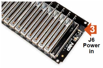
2.3 Power Up BATT-14CEMULATOR and RD33771CDSTEVB
Plug the power supply to the BATT-14CEMULATOR battery cell emulator board.
Powering the BATT-14CEMULATOR also powers the RDCV33771C cell controller board.
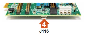
2.4 Connect the USB Serial Cable to MPC5775B-EVB and PC
Connect the micro-USB cable to J116 micro-USB port for OpenSDA connection for programming and debug. Connect the USB side to the computer.
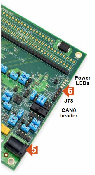
2.5 Power the MPC5775B-EVB
Connect 12 V power supply to power socket on your MPC5775B-EVB low-cost development board.
Make sure the status LEDs D14, D15, D16, and D32 for voltage levels 3.3 V, 5 V, 1.25 V and 12 V supply respectively are glowing green on the board.
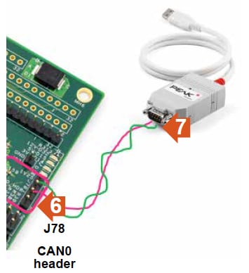
2.6 Connect the CAN With PCAN Tool
Connect CAN High and Low signals of J78 to PCAN tool CAN high and low. MPC5775B-EVB:
J78 pin 2 is CAN0_High
J78 pin 3 is CAN0_Low
Connect the CAN_H and CAN_L signals of J78 of MPC5775B-EVB to PCAN USB CAN_H (pin 7) and CAN-L (pin 2) via two jumper cables.
3. Build, Load
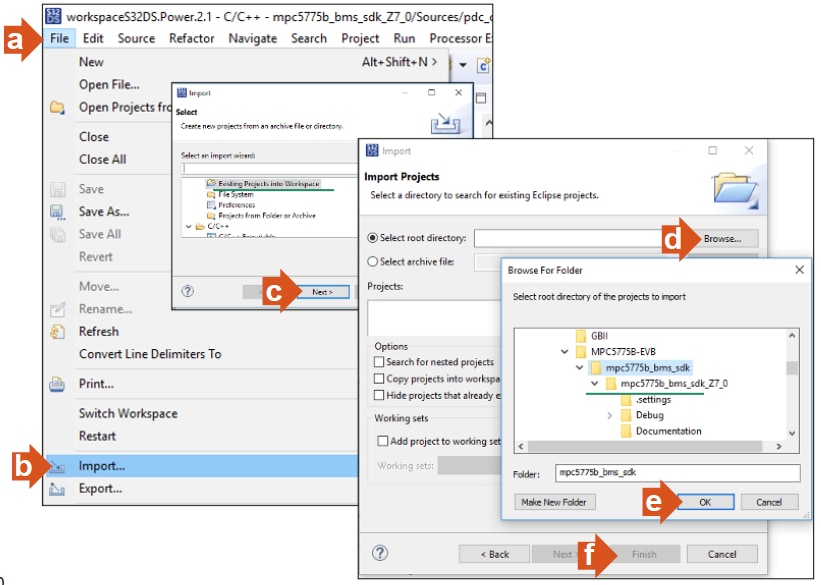
3.1 Import the Demo Project Using Your IDE
Import the MPC5775B_BMS_SDK_SW project into S32 Design Studio for Power Architecture®IDE
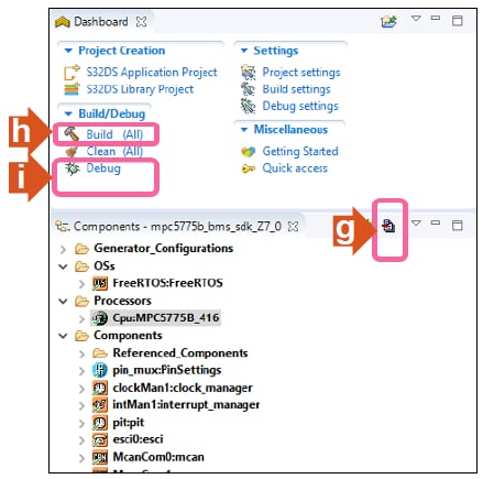
3.2 Generate Processor Expert Codes and Compile the Binary Image
Build and run the program to generate the processor expert codes, compile and build the image.
3.3 Connect the PCAN Tool USB to the PC
Connect the USB connector of PCAN tool to the computer USB port.
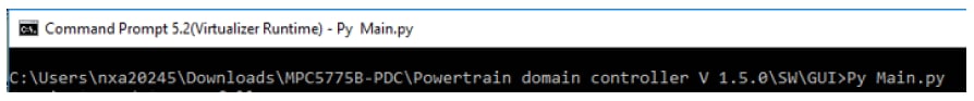
3.4 Run the GUI Software
Open the “Command Prompt” from Windows and execute the Py Main.py (file included in the GUI folder) in the command shell.
Make sure you first install Python 3.7 64-bit version and PyQt5 and NumPy packages.
3.5 Setup the GUI Link
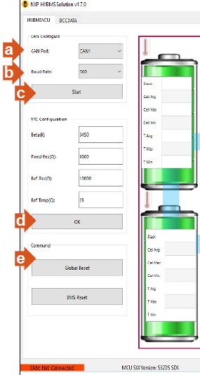
- Select CAN1
- Set CAN baud rate to 500Kbps
- Click Start, now the CAN link establish with the main controller board
- Click OK
- Initiate global reset to BMS system by clicking Global Reset
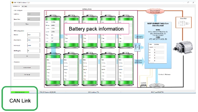
- Observe the battery pack information: the GUI interface after communication has been established:
Adjust the battery levels via BATT-14CEMULATOR and observe the GUI for individual cell data in BCCDATA tab:
On this page
- 1.1
Get Started With the MPC5775B/E-EVB
- 1.2
Download the MPC5775B-BatterySystem_SDK
- 1.3
Download the MPC5775B-BatterySystem_GUI
- 1.4
Get Your Integrated Development Environment (IDE)
- 1.5
Get Python 3.7