Getting Started with S32K3 AWS IoT Core
Contents of this document
-
Hardware Setup
-
Get Software
-
Setup Your AWS Account
-
Build, Run
-
Debugging
Sign in to save your progress. Don't have an account? Create one.
1. Hardware Setup
The S32K3X4EVB-T172, an evaluation and development board for general-purpose industrial and automotive applications, is needed for starting this demo.
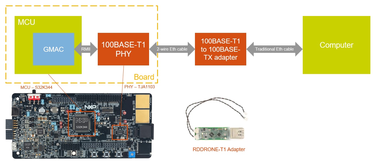
Note: The +12 V power supply and micro USB cable are not part of the package. The +12 V connector is a center-positive barrel type with outer 5.5 mm and inner 2.1 mm diameter. Additionally, all demos require Internet connection and in order to test them, an Ethernet Media Converter is required. The following NXP product can be used: RDDRONE-T1ADAPT.
1.1 Get Familiar With the Board
Based on the 32-bit Arm Cortex-M7 S32K3 MCU in a 172 HDQFP package, the S32K3X4EVB-T172 offers dual cores configured in lockstep mode, ASIL D safety hardware, HSE security engine, OTA support, advanced connectivity and low power.
The S32K3X4EVB-T172 offers a standard-based form factor compatible with the Arduino® UNO pin layout, providing a broad range of expansion board options for quick application prototyping and demonstration.
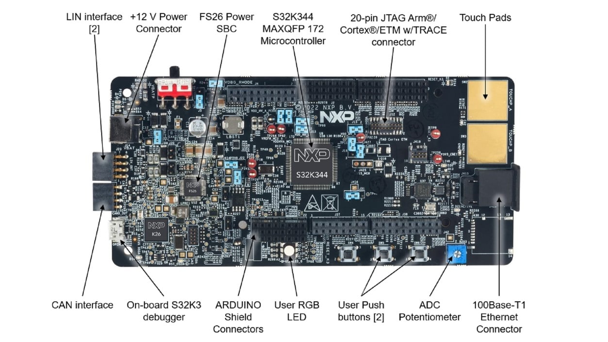
Additional information can be found in the HW User Manual (sign in on the NXP website required). Visit S32K3X4EVB-T172 web page for general information including features, block diagrams and design resources.
1.2 Set Up Jumpers in the S32K3X4EVB-T172 Evaluation Board
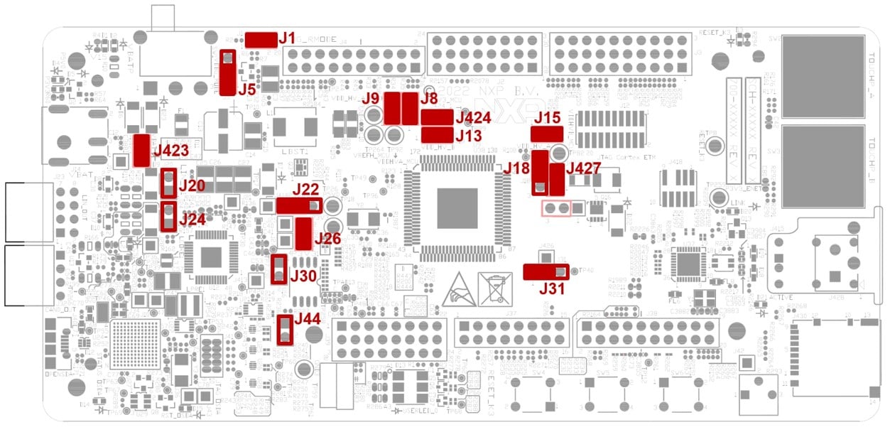
Default Jumper settings
| Jumper | State | Notes |
|---|---|---|
J1 |
CLOSED | Disabled FS26 watchdog after power-up |
J5 |
1-2 | Select voltage level for FS26 DEBUG pin |
J8 |
CLOSED | External circuits powered from VDD_HV_B domain |
J9 |
CLOSED | External circuits powered from VDD_HV_A domain |
J427 |
CLOSED | The MCU peripherals powered from the VDD_HV_A domain |
J15 |
CLOSED | The MCU peripherals powered from the VDD_HV_B domain |
J18 |
1-2 | 5 V for the VDD_HV_A domain |
J13 |
1-2 | 3.3 V for the VDD_HV_B domain |
J20 |
OPEN | LIN1 Commander* mode |
J22 |
1-2 | 5 V from FS26 SBC |
J24 |
OPEN | LIN2 Commander* mode |
J26 |
CLOSED | 3.3 V from FS26 SBC |
J30 |
OPEN | FS26 wake inputs |
J31 |
1-2 | V15 domain powered from FS26 SBC |
J44 |
OPEN | On-board debugger UART pins |
J423 |
CLOSED | 12 V from J14 connector |
J424 |
CLOSED | Connect 3.3 V voltage signal with 3.3 V MCU power domain option |
1.3 Plug in the Power Supply
Switch SW1 to the OFF position (fully to the right).
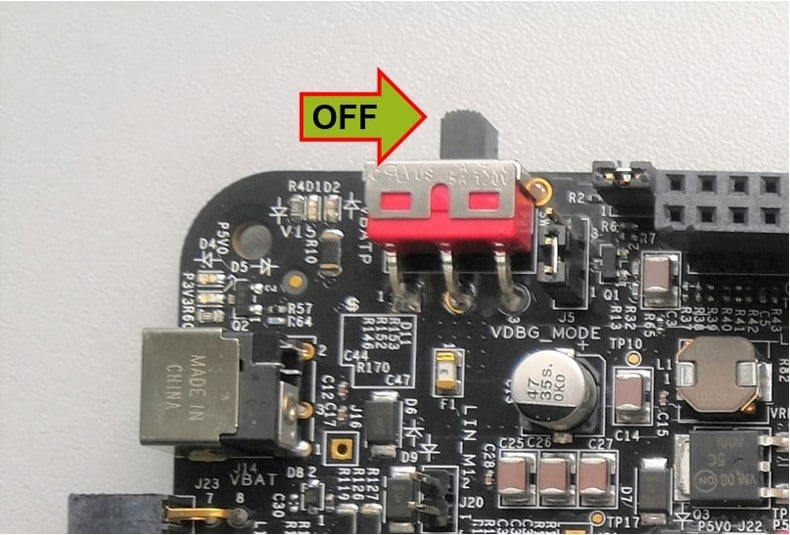
Connect the 12 V power supply adapter and switch SW1 to the ON position (fully to the left).
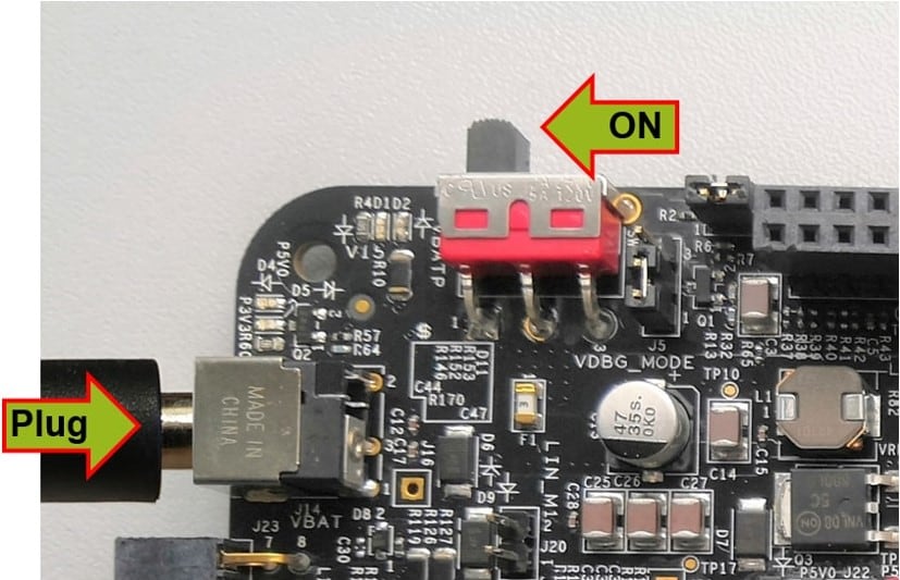
When power is applied to the EVB, four orange LED's adjacent to the voltage regulators show the presence of the supply voltages (12 V, 5 V, 3.3 V and 1.5 V).
1.4 Connect the Debugger Cable
Connect a micro-USB cable to the J40 connector to debug via the on-board S32K3 debugger.
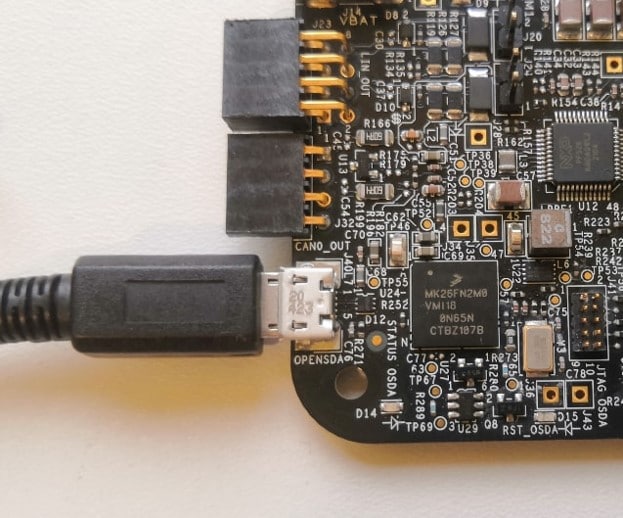
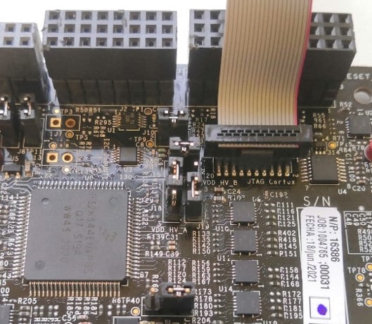
Or use JTAG connector to to connect external S32K3 debugger.
Additional information about setting up the hardware can be found in Chapter 6 (S32K3X4EVB-T172 - Startup) of the HW User Manual (sign in on the NXP website required).
1.5 Ethernet Connection
100BASE-T1 2-Wire Automotive Ethernet provides 100 Mbps connections over simple twisted 2-wires for a distance of up to 15 meters. The line signaling on the wire is not directly compatible with traditional 100BASE-TX (RJ45) connections, but a physical adapter may be used. Otherwise it is the same as traditional Ethernet. The picture below describes the setup.
2. Get Software
2.1 Installing Software for S32K3 AWS IoT Core
Video showcasing how to install the softwares.
2.2 Get the Integrated Development Environment
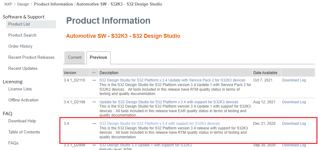
Download and install S32 Design Studio IDE for S32 Platform version 3.4.
NXP AWS IoT Core for S32K344 was designed in NXP's S32 Design Studio for S32 Platform v3.4 Update 3 IDE.
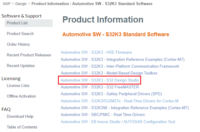
S32 Design Studio platform executable can be found by navigating to Automotive SW - S32K3 - S32 Design Studio, going to the Previous tab and selecting S32 Design Studio for S32 Platform v.3.4 with support for S32K3 devices, then downloading S32DS.3.4_b201217_win32.x86_64.exe.
DOWNLOAD S32 DESIGN STUDIO IDE
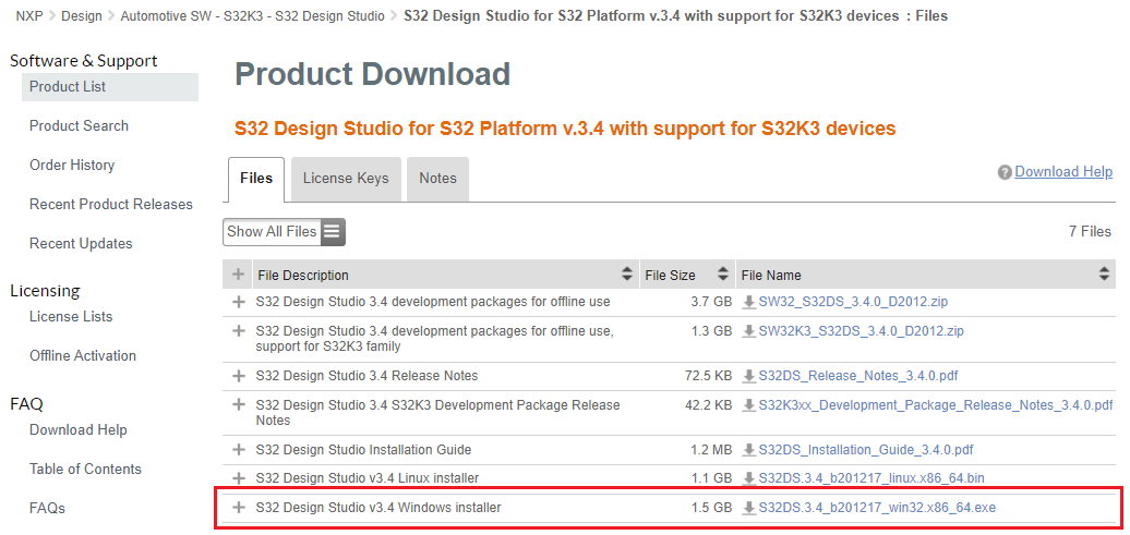
For more information on detailed installation of IDE, please follow the Installation Guide.
2.3 Install the S32K3xx Development Package
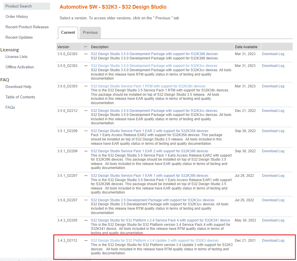
Additionally, the S32 Design Studio for S32 Platform v.3.4 Update 3 with support for S32K3 devices package must be installed on top of S32 Design Studio for S32 Platform v.3.4 with support for S32K3 devices.
The Update 3 can be found in the same location as the S32 Design Studio platform executable by navigating to Automotive SW - S32K3 - S32 Design Studio, going to the Current tab and selecting S32 Design Studio for S32 Platform v.3.4 Update 3 with support for S32K3 devices, then downloading SW32K3_S32DS_3.4.3_D2112.zip.
DOWNLOAD S32K3xx DEVELOPMENT PACKAGE
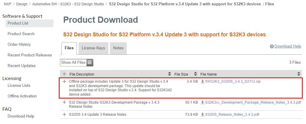
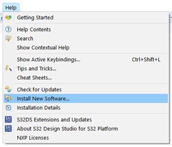
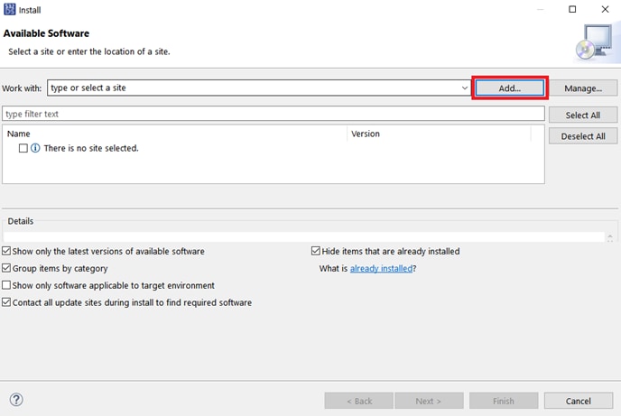
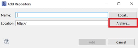
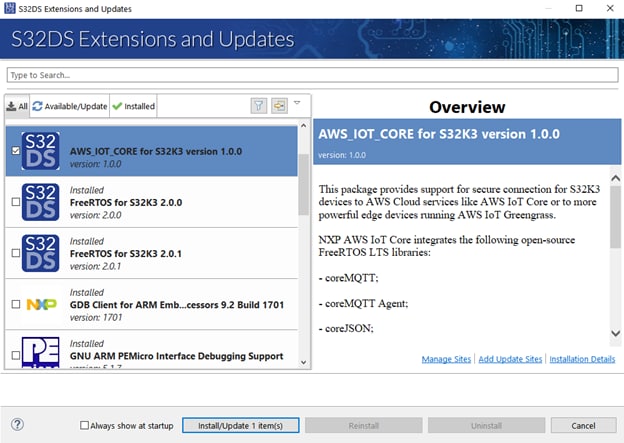
The downloaded archive can be installed by going into the Help → Install New Software… menu in S32DS, selecting Add…, then Archive… and browsing to the archive.
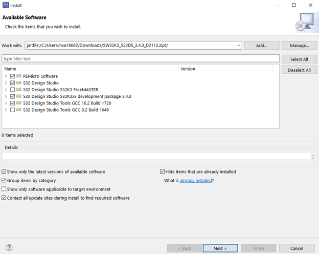
Next, select the software packages shown in the picture below and continue the installation process.
2.4 Pre-required Software
Using NXP AWS IoT Core for S32K344 requires installation of the following NXP software products:
- S32K3 Real-Time Drivers Version 2.0.1
- FreeRTOS version 2.0.1 release for S32K3 platforms
- SW32K3 TCPIP Stack version 1.0.1 HF1
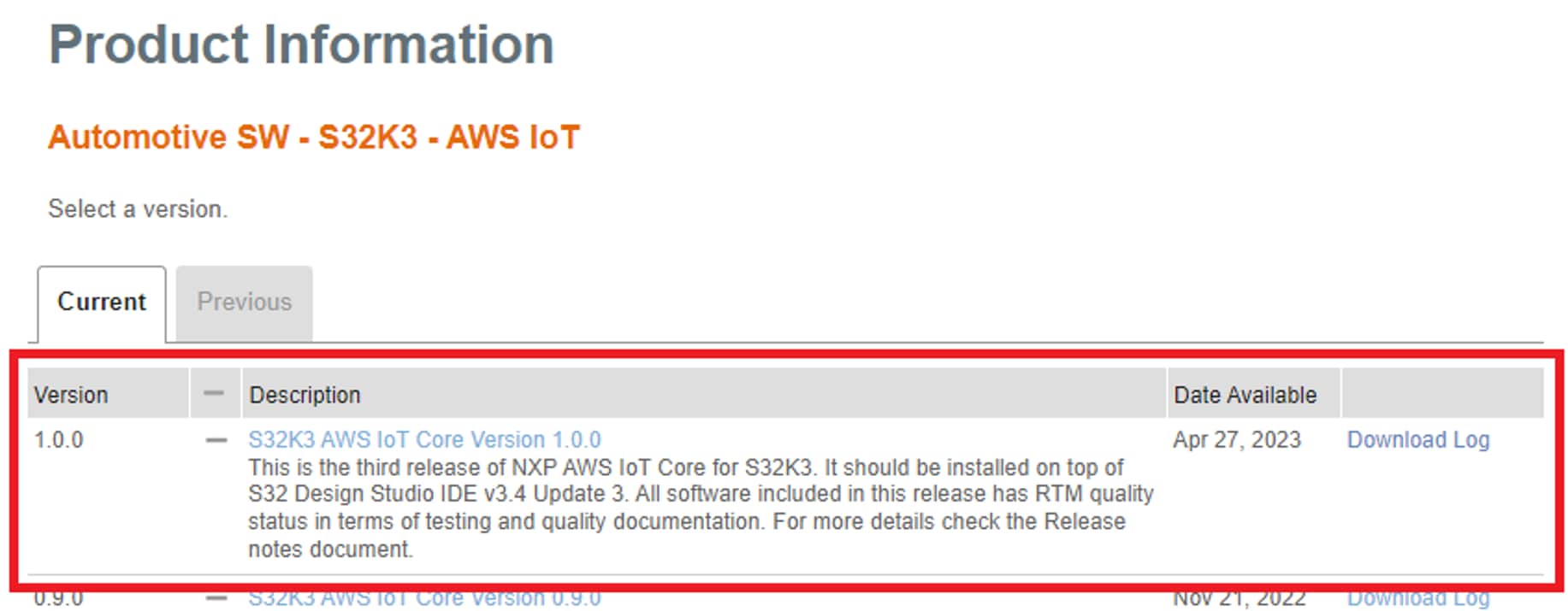
- S32K3 AWS IoT Core Version 1.0.0
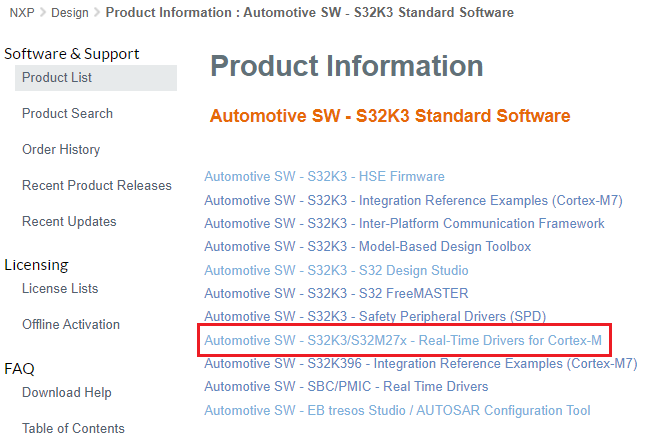
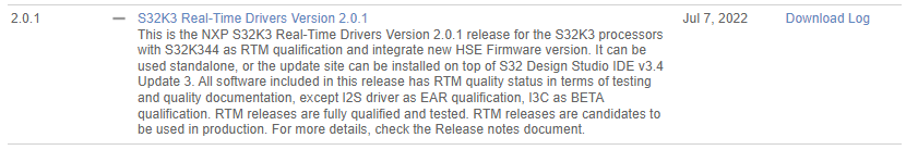
2.5 Get the Real Time Drivers
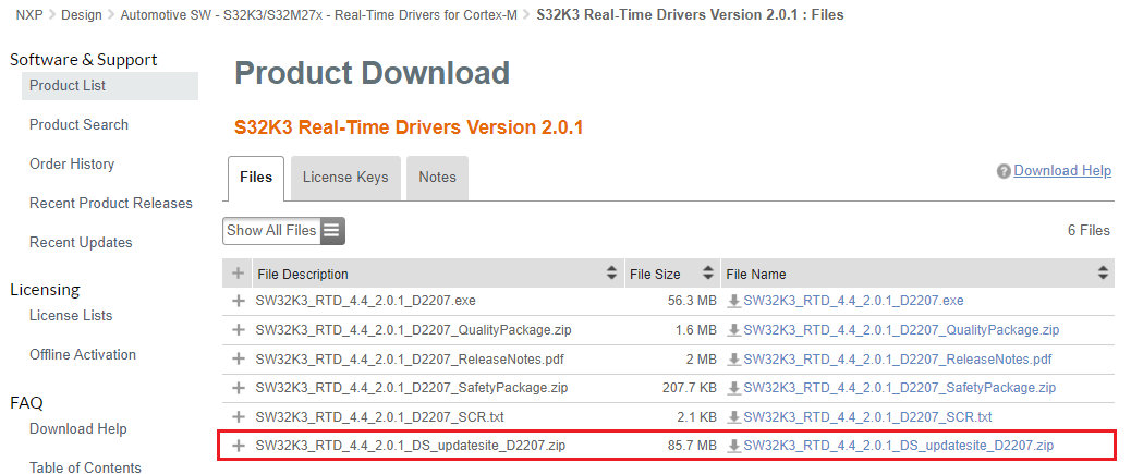
Automotive SW - S32K3 Standard Software → Automotive SW - S32K3 - Real-Time Drivers for Cortex-M → S32K3 Real-Time Drivers Version 2.0.1 → SW32K3_RTD_4.4_2.0.1_DS_updatesite_D2207.zip
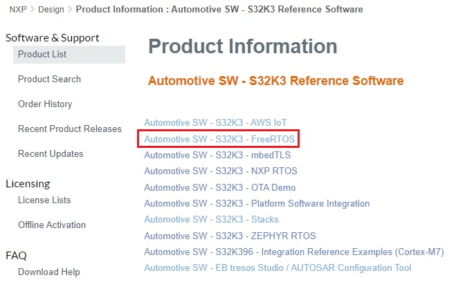
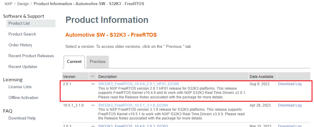
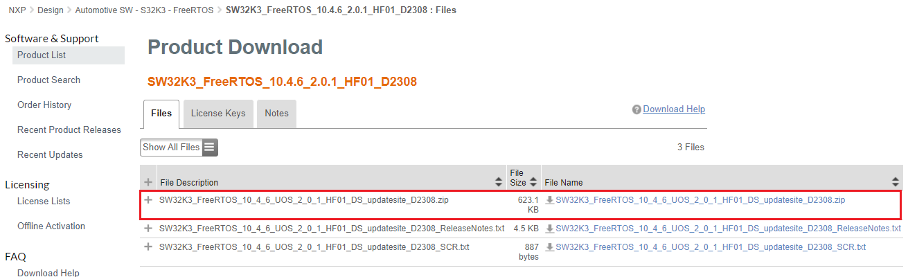
2.6 Download FreeRTOS
Automotive SW - S32K3 Reference Software → Automotive SW - S32K3 - FreeRTOS → SW32K3_FreeRTOS_10.4.6_2.0.1_D2209 → SW32K3_FreeRTOS_10_4_6_UOS_2_0_1_DS_updatesite_D2209.zip.
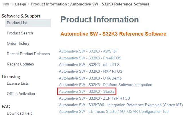
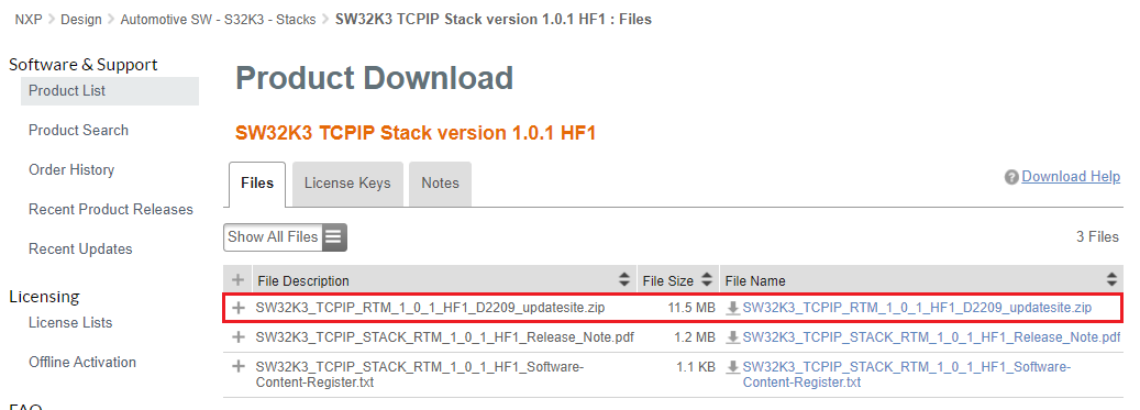
2.7 Download TCP/IP Stack
Automotive SW - S32K3 Reference Software → Automotive SW - S32K3 - Stacks → SW32K3 TCPIP Stack version 1.0.1 HF1 → SW32K3_TCPIP_RTM_1_0_1_HF1_D2209_updatesite.zip.

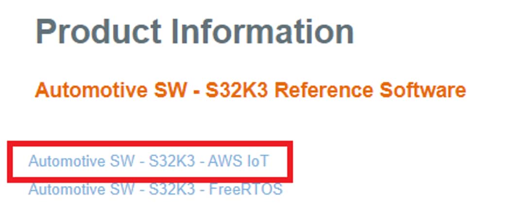
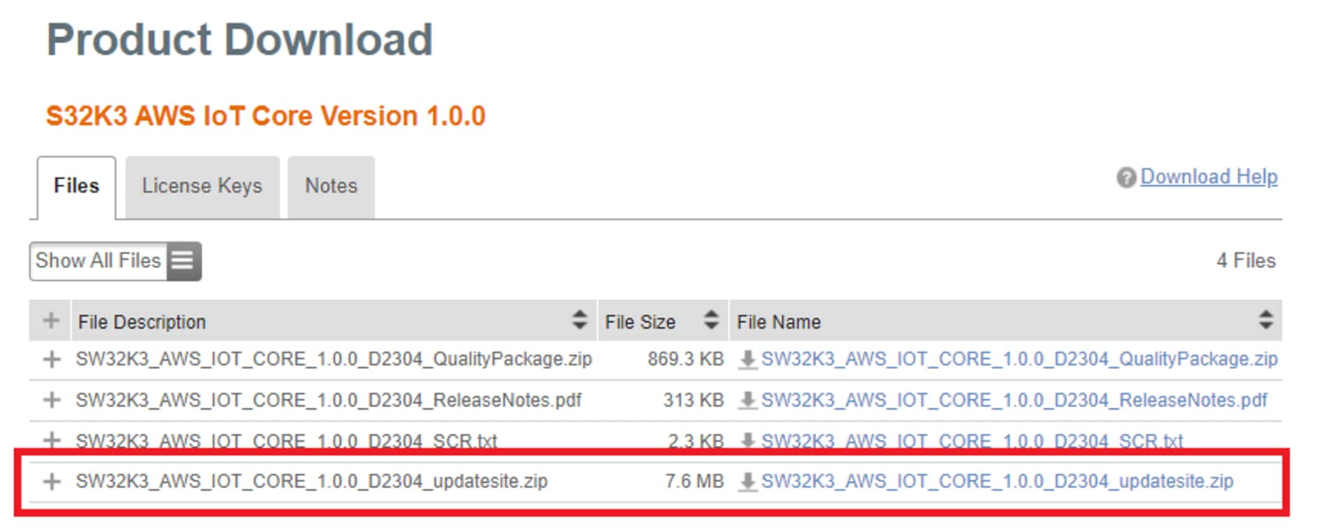
2.8 Download AWS IoT Core
Automotive SW - S32K3 Reference Software → Automotive SW - S32K3 - AWS IoT → S32K3 AWS IoT Core Version 1.0.0 → SW32K3_AWS_IOT_CORE_1.0.0_D2304_updatesite.zip.
2.9 Add Downloaded Update Sites to S32 Design Studio
All the three SW above will be downloaded in the form of Update Sites for S32 Design Studio (.zip archives), which can be installed in S32 Design Studio by following these steps:
- Choose Help → S32DS Extensions and Updates from the menu bar and select Add Update Sites
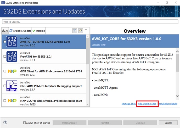
- Navigate to the directory with the downloaded ZIP file. Choose it and click Open, then click OK
- From the S32DS Extensions and Updates dialog select and install the required packages, mentioned above
All the steps mentioned above must be followed for each of the dependencies.
2.10 Other Software Required to Develop and Debug Applications for the Device
NXP AWS IoT Core makes use of the HSE security engine, so HSE FW 0.2.1.0 RTM must be installed on the device.
The firmware (HSE_FW_S32K3XX_0_2_1_0.exe) can be downloaded from Automotive SW - S32K3 Standard Software → Automotive SW - S32K3 - HSE Firmware → HSE FW 0.2.1.0 RTM Release.
A Demo Application is provided separately and contains details on how to provision HSE Firmware on new device from factory and demonstrates common use cases of its security features. The Demo Application can be found here (login required).
The steps to install the firmware are the following:
- Download the HSE firmware and the Demo Application from the locations mentioned above
- Install them using the guided setup
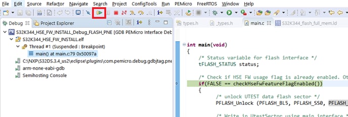
- Import the firmware installation example (
<DemoExamples_location>/S32K3_HSE_DemoExamples/Device_Configuration/S32K344_HSE_FW_INSTALL) in S32 Design Studio by selecting File → Import… → General → Existing Projects into Workspace and browsing to the example location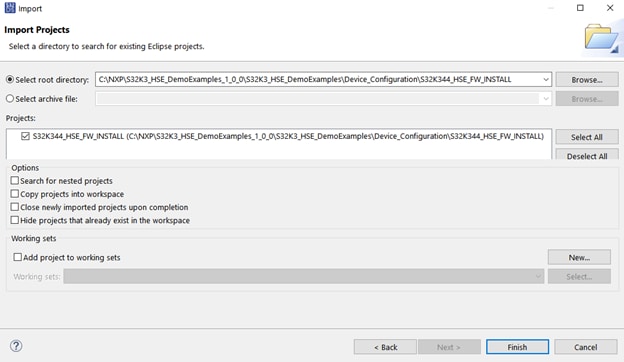
- Build the project
- Debug the demo

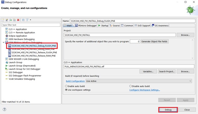
- To check if the HSE firmware was installed correctly, you can pause the application and check the value of the gHseFwVersion variable
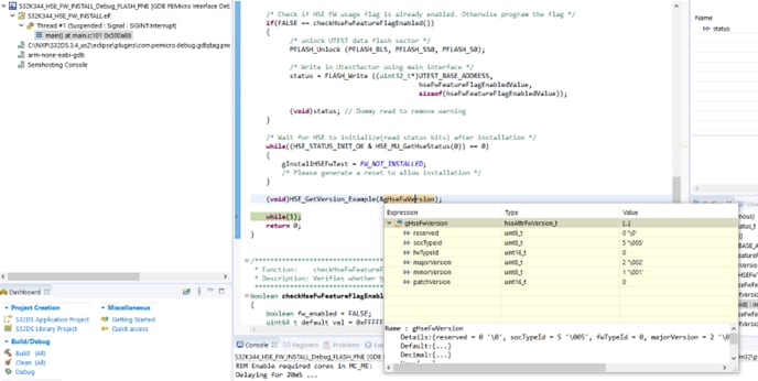
For more details please refer to the Readme.md file included in the project.
The S32K3xx Security Overview and Bring Up Training (sign-in required) talks about security features in S32K3. You can also visit our secure documents (NDA required) area for in-depth security details. Registration guide for the secure access rights can be found here.
3. Setup Your AWS Account
If you do not have an existing AWS account and user, refer to the online AWS documentation at Set up your AWS Account . To get started, follow the steps outlined in the sections below:
Pay special attention to the Notes.
3.1 Create Resources in AWS IoT
Refer to the online AWS documentation at Create AWS IoT Resources . Follow the steps outlined in these sections to provision resources for your device:
Pay special attention to the Notes.
3.2 Provision the Device With Credentials
Provisioning the device with credentials is showcased in the aws_pkcs11_mqtt_s32k344 demo. In addition to the standard MQTT example, this example uses the corePKCS11 library to provision the device with the client certificate and private key. The corePKCS11 library is integrated with the S32K3 hardware security engine (HSE).
An additional macro was added to the configuration in demo_config.h: #define democonfigPROVISION_DEVICE
This macro must be defined to enable provisioning of the device with the client certificate and private key defined below. After running the example once, the macro can be undefined, as the certificate will be stored in FLASH and the private key in the HSE.
The provisioning is implemented in the vDevModeKeyProvisioning() function implemented in src/ aws_dev_mode_key_provisioning.c. This function is invoked by the InitTask() located in src/main.c, if the democonfigPROVISION_DEVICE macro is defined.
Alternatively, the mbedTLS library included in NXP AWS IoT Core can be used, also integrated with the S32K3 hardware security engine (HSE).
4. Build, Run
NXP AWS IoT Core contains several demos showcasing the AWS IoT Core connectivity. The steps describing how to import, build and run the demo apply to all the included demos, but we recommend starting with the aws_mqtt_s32k344 demo to confirm that the device is able to communicate with AWS IoT Core.
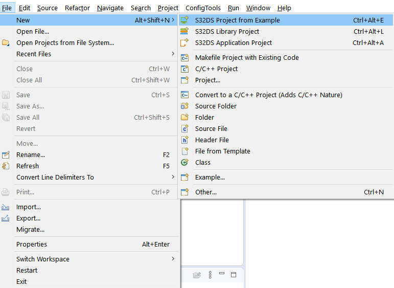
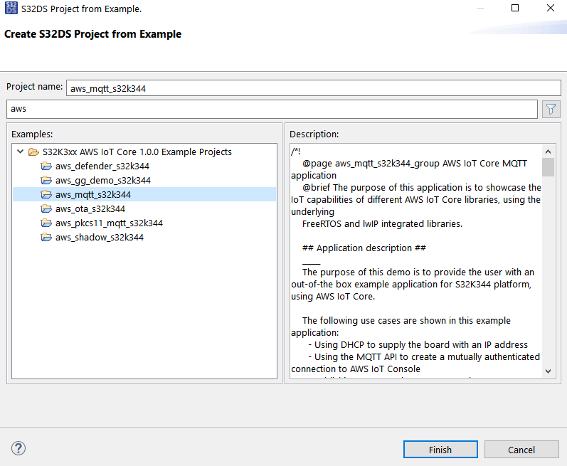
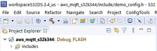
4.1 Create S32DS Project Starting From the aws_mqtt_s32k344 Example
After opening S32 Design Studio, go to File → New S32DS Project From Example and select aws_mqtt_s32k344 (you can search it by typing aws into the search box). Then click on Finish.
4.2 Configure demo_config.h
In order to successfully build the project and connect to AWS IoT Core the include/demo_config.h file must be filled in with information regarding the AWS IoT endpoint and the IoT thing created in the Create resources in AWS IoT section.
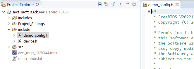
A few macros are mandatory (they are commented out in the file as a reference, but should be defined by the user):
- democonfigMQTT_BROKER_ENDPOINT
- democonfigMQTT_BROKER_PORT
- democonfigROOT_CA_PEM
- democonfigCLIENT_CERTIFICATE_PEM
- democonfigCLIENT_PRIVATE_KEY_PEM
Details on how to set up each of the macro can be found in the include/demo_config.h file comments.
4.3 Generate Configuration Code
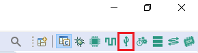
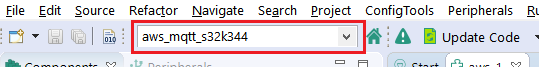
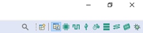
Double click on aws_mqtt_s32k344.mex file or open the peripherals view by clicking the symbol (mentioned below) on the upper right corner of S32 DS.
Select the current project (aws_mqtt_s32k344) from the top left of the window.
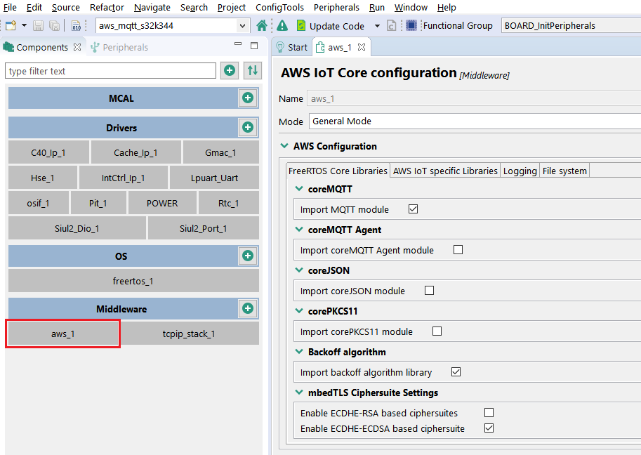
The configuration of the different components can be updated by selecting any of them (not needed for the current example). This is an example of how the aws component looks like:
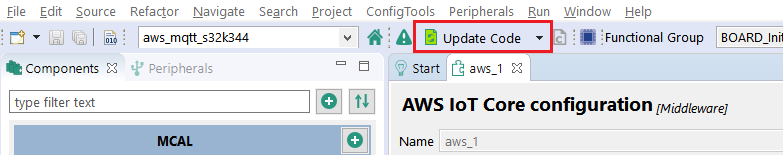
Click on the Update Code button (green when there are new configuration files to be generated).
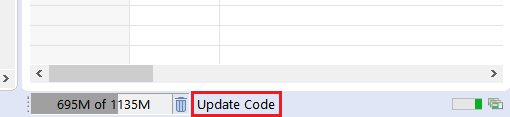
Wait for the code generation to be completed before continuing to the next step (when the Update Code message in the lower right disappears).
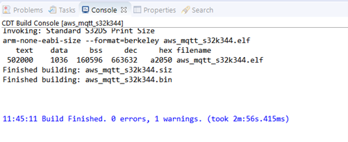
4.4 Build the Project
Switch again to the C/C++ perspective by clicking the symbol on the upper right corner of S32 DS.
Click on the Build button.
Wait for the build action to be completed before continuing to the next step.
4.5 Run the Demo
Connect the debugger, connect the board to the Internet through the J428 port and power it up as described in the Set up device hardware section.
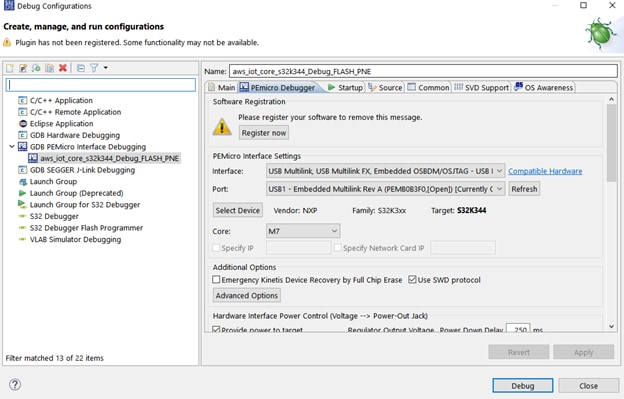
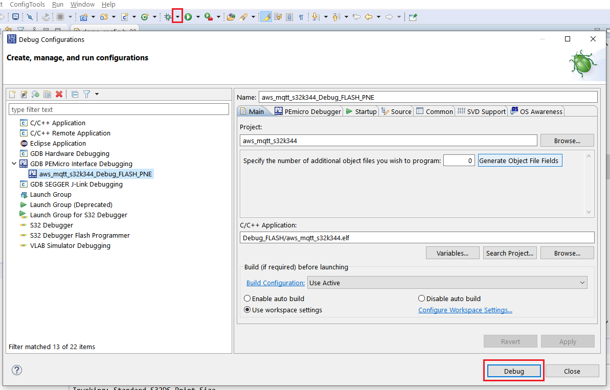
Click on the downward arrow corresponding to the Debug button in S32 DS and select Debug Configurations…. Select aws_mqtt_s32k344_Debug_FLASH_PNE and click on the Debug button.
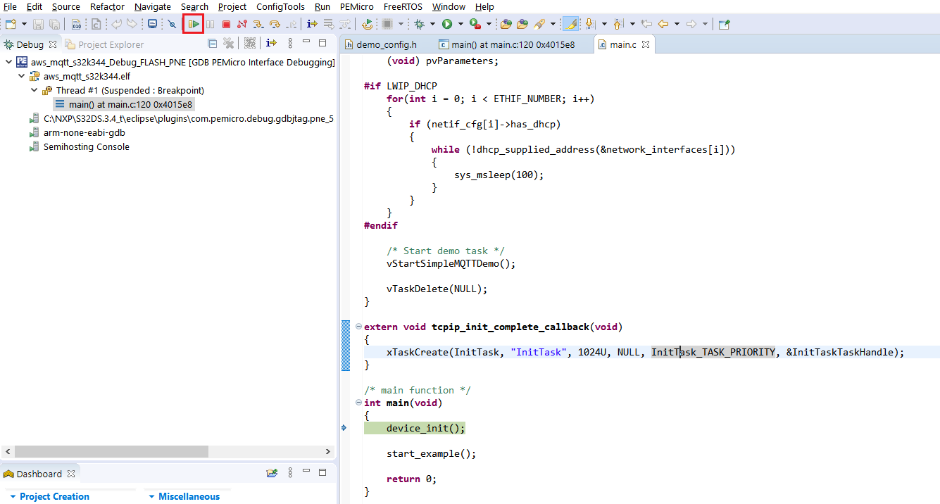
Wait until the debug session is started and then click the Resume button to continue the execution of the application.
4.6 Verify Messages in AWS IoT Core
From the AWS IoT Core console , select Test from the navigation pane, and choose MQTT test client. Select Subscribe to a topic, enter the topic (or use the # wildcard to see all topics) and then choose Subscribe. You should see messages being displayed as they are received.
5. Debugging
5.1 Debugging
You can check the progress of the execution by attaching a serial terminal on the virtual COM associated to the OpenSDA interface (which can be checked in Device Manager).

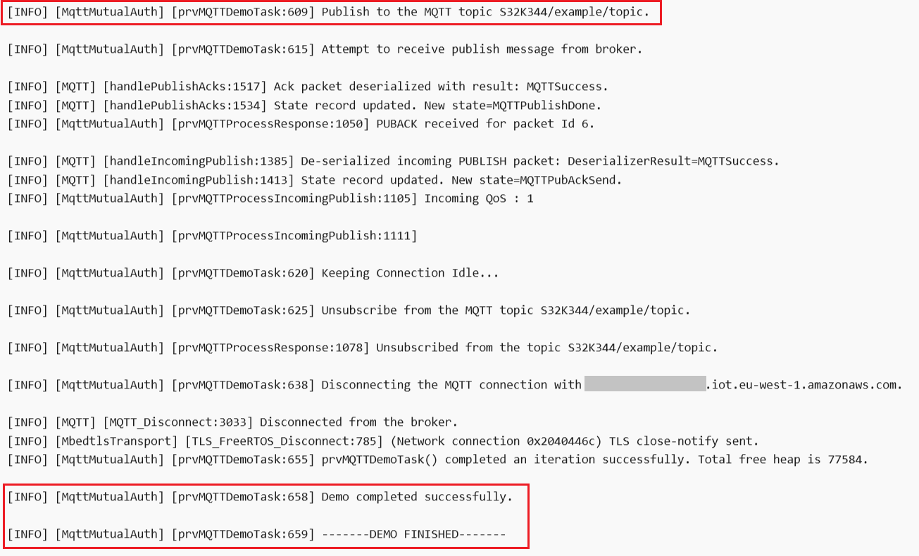
When the example starts running, a log similar to this will be printed:
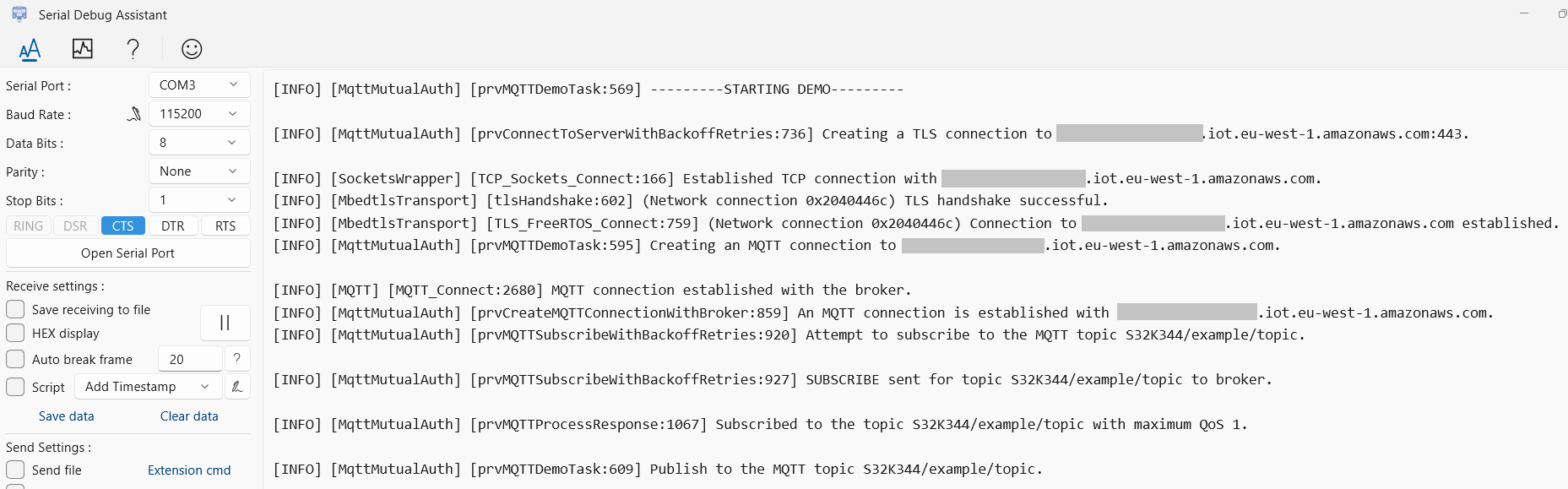
If execution is successful, besides verifying the MQTT messages are received by AWS IoT Core as described in the Verify messages in AWS IoT Core section, you should see the following message at the end of the execution:
The logging levels can be updated from the Peripherals view, accessed as indicated in the Build & Run the demo section, step 3. The logging settings are in the Logging tab of the aws component:
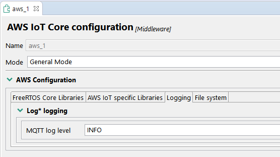
If the logging settings or anything else is updated in the configurator, code will need to be generated and built again, as indicated in the Build & Run the demo section, steps 3 and 4.
When running the project as indicated in the Run the demo section, you can use the debugger embedded in S32 Design Studio (e.g. you can set breakpoints before clicking Resume, or Pause the execution and inspect the currently executed code). Details regarding debugging can be found in the S32DS User Guide (Chapter Debugging), located in the S32 Design Studio installation:
<S32DS install dir>/S32DS/help/pdf/S32DS_User_Guide.pdf Demos
NXP AWS IoT Core support product offers the following S32 Design Studio projects as examples
aws_mqtt_s32k344
This example is used to create an MQTT connection to your AWS IoT account. The device will publish MQTT topic messages to the AWS endpoint and is able to receive publish messages from the server to which it will reply with acknowledgement messages.
This example project was created based on the MQTT_Mutual_Auth demo .
aws_pkcs11_mqtt_s32k344
In addition to the standard MQTT example, this example uses corePKCS11 to provision the device with the client certificate and private key.
This example project was created based on the corePKCS11_MQTT_Mutual_Auth demo .
aws_ota_s32k344
This example is used to showcase the capabilities of over-the-air update in AWS IoT Core.
The example starts the OTA Agent and listens for incoming updates requests from the AWS server. Once the update starts, a new firmware image will be downloaded to flash and the device will restart, loading the new image.
This example project was created based on the Ota demo.
aws_defender_s32k344
This demo creates a single application task that demonstrates how to collect metrics, construct a device defender report in JSON format, and submit it to the AWS IoT Device Defender service through a secure MQTT connection to the AWS IoT MQTT Broker. The demo includes the standard networking metrics as well as custom metrics. For custom metrics, the demo includes:
- A metric named ""task_numbers"" which is a list of FreeRTOS task IDs. The type of this metric is ""list of numbers""
- A metric named ""stack_high_water_mark"" which is the stack high watermark for the demo application task. The type of this metric is ""number""
This example project was created based on the Device_Defender demo.
aws_shadow_s32k344
This demo shows how to use the AWS IoT Device Shadow library to connect to the AWS Device Shadow service. It uses the coreMQTT library to establish an MQTT connection with TLS (Mutual Authentication) to the AWS IoT MQTT Broker and the coreJSON library parser to parse shadow documents received from the AWS Shadow service.
The demo shows basic shadow operations, such as how to update a shadow document and how to delete a shadow document. The demo also shows how to register a callback function with the coreMQTT library to handle messages like the shadow /update and /update/delta messages that are sent from the AWS IoT Device Shadow service.
This example project was created based on the Device_Shadow demo.
aws_gg_demo_s32k344
This project is showcasing the Greengrass capability by connecting S32K344 running AWS IoT Core (representing a Greengrass device) to S32G2 RDB2 running GoldVIP (representing the Greengrass core) and publishing diagnostics to a SiteWise dashboard. It requires extra prerequisites, which are mentioned in the demo description.
For details regarding running the demos please consult the description.txt file of the examples.
Design Resources
Support
Troubleshooting
This chapter describes some of the common problems which may be encountered while running the AWS IoT Core demo.
The Software Cannot Be Uploaded Into MCU and the Power Domain LEDs Blink Periodically
This is caused by the watchdog in Safety SBC that is not fed properly and resets MCU. In such a case do a power-up procedure according to the steps in Plug in the Power Supply section.
Demo Execution Stuck in InitHseMbedTls()
This problem indicates that the HSE FW was not properly installed. Please check again the steps in section Other software required to develop and debug applications for the device section.
Demo Execution Stuck in InitTask()
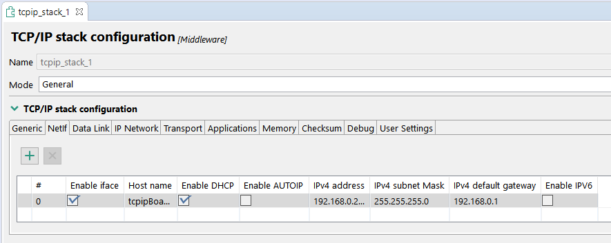
The board is getting an IP address trough DHCP. If the execution is stuck in the following loop:
while (!dhcp_supplied_address(&network_interfaces[i]))It may indicate that the board is not supplied with an IP address, which can happen if the DHCP server is not working properly.
If you do not want to use DHCP, you can change the settings in the Peripherals view, in the tcpip_stack component, Netif tab.
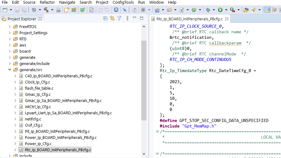
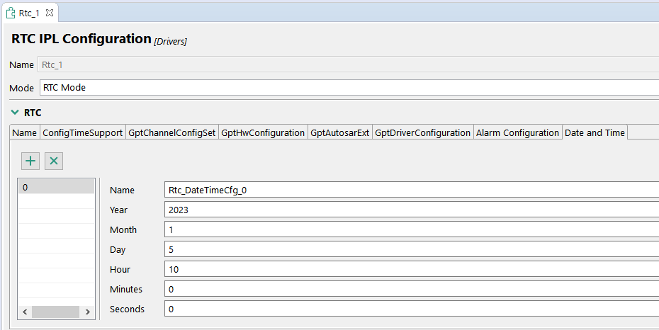
ERROR: TLS Handshake Failed Trying to Connect. X509 - Certificate Verification Failed
Seeing this error in the serial log might indicate that validation of the server certificate is failing. One possible cause would be wrong configuration of the current time in the RTC. This can be updated either by directly modifying the generate/src/Rtc_Ip_BOARD_InitPeripherals_PBcfg.c file or updating the configuration in the Peripherals view and generating the code using Update Code:
For more information, refer to the AWS online documentation on Troubleshooting AWS IoT.
Forums
On this page
- 1.1
Get Familiar With the Board
- 1.2
Set Up Jumpers in the S32K3X4EVB-T172 Evaluation Board
- 1.3
Plug in the Power Supply
- 1.4
Connect the Debugger Cable
- 1.5
Ethernet Connection
- 2.1
Installing Software for S32K3 AWS IoT Core
- 2.2
Get the Integrated Development Environment
- 2.3
Install the S32K3xx Development Package
- 2.4
Pre-required Software
- 2.5
Get the Real Time Drivers
- 2.6
Download FreeRTOS
- 2.7
Download TCP/IP Stack
- 2.8
Download AWS IoT Core
- 2.9
Add Downloaded Update Sites to S32 Design Studio
- 2.10
Other Software Required to Develop and Debug Applications for the Device
- 4.1
Create S32DS Project Starting From the aws_mqtt_s32k344 Example
- 4.2
Configure demo_config.h
- 4.3
Generate Configuration Code
- 4.4
Build the Project
- 4.5
Run the Demo
- 4.6
Verify Messages in AWS IoT Core