デザイン・ファイル
2 設計・ファイル
-
シミュレーションとモデル
IBIS models for LPC2290-2292-2294 pkg LQFP-144
-
シンボルおよびフットプリント
LPC2xxx ORCAD symbols
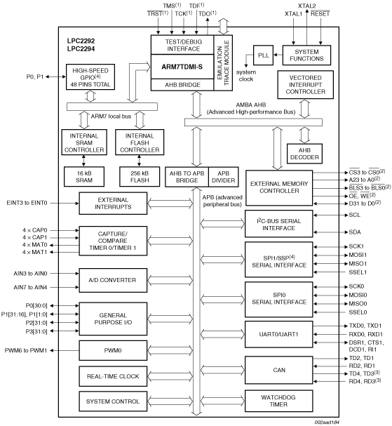
The LPC2292/2294 microcontrollers are based on a 16/32-bit Arm7TDMI-S™ CPU with real-time emulation and embedded trace support, together with 256 kB of embedded high-speed flash memory. A 128-bit wide memory interface and a unique accelerator architecture enable 32-bit code execution at the maximum clock rate. For critical code size applications, the alternative 16-bit Thumb mode reduces code by more than 30 % with minimal performance penalty.
With their 144-pin package, low power consumption, various 32-bit timers, 8-channel 10-bit ADC, 2/4 (LPC2294) advanced CAN channels, PWM channels and up to nine external interrupt pins these microcontrollers are particularly suitable for automotive and industrial control applications as well as medical systems and fault-tolerant maintenance buses. The number of available GPIOs ranges from 76 (with external memory) through 112 (single-chip). With a wide range of additional serial communications interfaces, they are also suited for communication gateways and protocol converters as well as many other general-purpose applications.
Remark:Throughout the data sheet, the term LPC2292/2294 will apply to devices with and without the /00 or /01 suffix. The suffixes /00 and /01 will be used to differentiate from other devices only when necessary.
Key features common for all devices
部品番号: LPC2292FBD144.
クイック・リファレンス ドキュメンテーションの種類.
1-5 の 29 ドキュメント
2 設計・ファイル
1 ソフトウェア・ファイル
注: より快適にご利用いただくために、ソフトウェアのダウンロードはデスクトップで行うことを推奨します。