デザイン・ファイル
2 設計・ファイル
-
シミュレーションとモデル
IBIS models for LPC2364-2366-2368-2378
-
シンボルおよびフットプリント
LPC2xxx ORCAD symbols
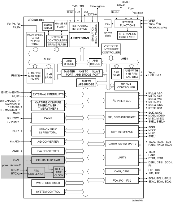
The LPC2361/2362 microcontrollers are based on a 16-bit/32-bit Arm7TDMI-S™ CPU with real-time emulation that combines the microcontroller with up to 128 kB of embedded high-speed flash memory. A 128-bit wide memory interface and a unique accelerator architecture enable 32-bit code execution at the maximum clock rate. For critical performance in interrupt service routines and DSP algorithms, this increases performance up to 30 % over Thumb mode. For critical code size applications, the alternative 16-bit Thumb mode reduces code by more than 30 % with minimal performance penalty.
The LPC2361/2362 are ideal for multi-purpose serial communication applications. They incorporate a 10/100 Ethernet Media Access Controller (MAC) (LPC2362 only), USB full speed device with 4 kB of endpoint RAM, four UARTs, two CAN channels, an SPI interface, two Synchronous Serial Ports (SSP), three I²C interfaces, and an I²S interface. This blend of serial communications interfaces combined with an on-chip 4 MHz internal oscillator, SRAM of up to 32 kB, 16 kB SRAM for Ethernet (available as general purpose SRAM for the LPC2361), 8 kB SRAM for USB and general purpose use, together with 2 kB battery powered SRAM make these devices very well suited for communication gateways and protocol converters. Various 32-bit timers, an improved 10-bit ADC, 10-bit DAC, one PWM unit, a CAN control unit, and up to 70 fast GPIO lines with up to 12 edge or level sensitive external interrupt pins make these microcontrollers particularly suitable for industrial control and medical systems.
部品番号: LPC2361FBD100.
クイック・リファレンス ドキュメンテーションの種類.
1-5 の 16 ドキュメント
2 設計・ファイル
2 ソフトウェア・ファイル
注: より快適にご利用いただくために、ソフトウェアのダウンロードはデスクトップで行うことを推奨します。