The clinical benchtop centrifuge is the work horse in the clinical diagnostics laboratory. Like many other industrial and
medical technologies, the centrifuge is an often-unseen player in the chain of tools needed to keep everyone safer and
healthier.
Drucker Diagnostics is a leader in the design and
production of clinical benchtop centrifuges located in central Pennsylvania, USA. Every day, countless number of patient samples
across the globe are processed by Drucker Diagnostics centrifuges for routine tests, blood bank and quick-turn (A.K.A. STAT)
scenarios. If you have ever had your blood tested, it was probably spun in a Drucker Diagnostics centrifuge.
You can find Drucker Diagnostic centrifuges in doctor’s offices, hospitals, emergency clinics and blood banks. Even our most
beloved furry best friends rely on Drucker Diagnostics centrifuges to stay happy and healthy.
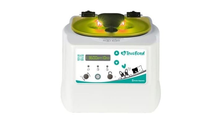
 The Drucker diagnostics Truebond Centrifuge for veterinary applications
The Path to Modern Centrifuge Engineering
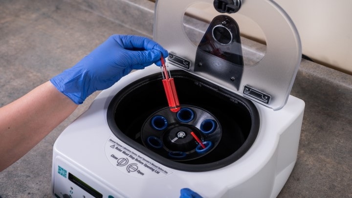
The operation principle of a centrifuge is straightforward: samples are placed in dedicated slots within the centrifuge,
typically designed for standard sample collection tubes. These samples are then spun at a controlled speed for a set duration.
During this spinning process, the components of the sample are physically separated based on their density and the forces
generated during spinning. For example, blood plasma or serum can be separated from other blood components like red blood cells,
white blood cells and platelets.
 Drucker TrueBond Centrifuge
At the core of a centrifuge is an electric motor and power electronics. The physical size and rating of the motor as well as the
scale of power control electronics can vary across different centrifuge models. Some applications require faster speeds (RPM)
and the ability to accommodate additional mass of the rotor assembly.
There is rarely a “one size fits all” design for a centrifuge. It is common to have several models to cover specialized
applications, each with different requirements for rotational speed and torque. Inside a typical centrifuge, one may encounter
any type of electric motor technology. Depending on the application requirements, the motor technology could range from a
synchronous AC machine to a Brushless Direct Current (BLDC) machine.
The control electronics must manage all the aspects of the centrifuge spin cycle. This includes speed control, detection of
operational issues such as rotor imbalance and excess vibration, electrical fault handling, safety and the operator interface.
It is common to find everything from legacy 8-bit microcontrollers to specialized “all in one” ICs based upon proprietary
architectures. At the surface level, designing a centrifuge may seem simple. However, developing a flexible control system that
meets a diverse set application requirement can pose many system design challenges.
Engineers need to be agile in their approach to centrifuge design to meet a diverse range of functional, cost and reliability
requirements. Uses of special ICs can lead to significant challenges in adapting designs to maintain a consist supply of end
product when there is a supply chain crunch.
Modularization and Cost Optimization with NXP LPC865 MCUs
The LPC865 family is the newest addition to the
low-power, low-pin count and space efficient
LPC800 series. A large focus area of the LPC865 is
motor control applications as it integrates two powerful Flex Timer Modules (FTM), a high-speed Analog to Digital Converter
(ADC) and analog comparators (ACMP).
Expand your knowledge Explore use cases that leverage
LPC865 MCUs.
 The Arm® Cortex®-M0+ LPC865 with Motor Control Peripherals
These peripherals are designed to work cooperatively through dedicated peripheral interconnects to implement all of the most
common motor control schemes.
The LPC865 motor control use cases span from simple brushless DC machines to Field Oriented Control for Permanent Magnet
Synchronous Machines (PMSM). Priced around $1.07 USD for 10k in the LQFP-64 Package, the LPC865 is a replacement for legacy 8-bit and 16-bit parts. In the case of the Drucker Diagnostics application, this is a
6x reduction from the current MCU price.
Additional benefits of migrating to a modern, low-cost 32-bit Cortex-M0+ MCU include:
- Ease of code development with a powerful CPU core
- Scalability to more complex motor control algorithms
- Ability to maintain portable code for a widespread CPU architecture
-
Ubiquity of toolchain support. Development workflows no longer require specialized toolchains for non-standard CPU
architectures. Developers can use open-source tools such as GCC with free development tools such as
MCUXpresso
-
Wide range of debug tooling such as the
NXP MCU-Link or the
Segger J-link that can be used with a wide range of different MCU products
Two other aspects of the LPC865 that speak to its ability to simplify designs and optimize BOM cost are the switch matrix and simple IC packaging.T
 The LPC865 SWM for Flexible Pin Assignment - LPC865 User Manual UM11607 Rev. 3 Fig 12 Page 107
For a better experience, download the
UM11607.
The SWM allows many of the peripherals to be routed to any pin, simplifying printed circuit board layout. This can be helpful in
low-cost applications that use lower cost PCB technology.
The LPC865 is offered in 10mm² LQFP64, 7mm² HVQFN48 and 5mm² HVQFN32 packages.
 The LPC865 Packaging and Pinout Offerings: Application Note AN13803 Rev 0 Fig 13 Page 8
For a better experience, download the
AN13803.
Engineers have flexibility to use a small 5mm² HVQFN32 package when IO needs are minimal. The LQFP64 package provides plenty of
IO when designs require additional GPIO pins for buttons, LCDs and electro-mechanical control such as solenoid drivers.
The Drucker Diagnostics LPC865 BLDC Motor Control Pilot Design
As a first step towards a modern design architecture, Drucker Diagnostics engineered a pilot design to evaluate the LPC865.
The intent of the pilot was to be a BLDC replacement for an existing design built around a synchronous AC motor and a legacy
8-bit MCU. All while taking steps towards a modularized design and achieving cost parity. The pilot design used an NXP LPC865
MCU,
Nexperia BUK9Y43-60E MOSFETS for the 3-phase bridge and an On Semiconductor
NCD83591MNTXG gate driver.
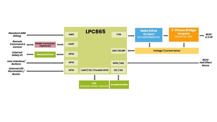
 The Drucker Diagnostics BLDC Pilot Design Architecture using the LPC865
An aspect of this pilot was to split the power electronics functions to gain agility over the power electronics architecture.
The generic nature of the LPC865 and gate drivers enables a significant degree of agility in control topologies. Switching from
a lookup table-based BLDC commutation scheme to a sensorless approach is possible with the same architecture.
In addition to the motor control features, the LPC865 has a large number of IOs that enable:
- Wiring to discrete buttons and LEDs
- Connectivity to both parallel and serial LCDs for the user interface
- I²/I3C interfaces to accelerometers to measure rotor imbalance
- A UART for external command and control
The availability of the additional IOs translates to a lower BOM cost as external IO expanders typically found in legacy 8-bit
designs are no longer required.
Many of the Drucker Diagnostics products come in variants with a range of user interface and IO needs. Some products have LCDs
for report operation state, while others have simple LED/pushbutton user interfaces. There are also requirements for controlling
ancillary functions in the product such as solenoids used for safety mechanics. The LPC865 makes a design transition as it has
just the right amount of IO capability to get all needed features in a single chip to reduce BOM cost.
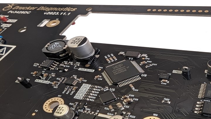
 The Drucker Diagnostics LPC865 Based BLDC Pilot Prototype
“By offering best in class technology solutions at a cost-effective price point, NXP enables Drucker Diagnostics to stay on
the leading edge and cost competitive with our product offerings to help make people safer, healthier and more productive.”
Tom Mallison – President Drucker Diagnostics.
Options for Growth in Capabilities and Connectivity
The LPC865 is a great solution for many baseline motor control applications.
It can be a “go to” for simple BLDC motors at a low cost but has enough power for more sophisticated applications needing Field
Oriented Control for PMSM machines.
There are detail application notes on how to achieve advanced motor control topologies with the LPC865:
The LPC865 can serve well in motor control applications with simple I/O requirements such as:
- Manual user control input / HMI via buttons
- As a motor control / IO Bridge coprocessor via I3C / I²C
-
As a node in on a distributed industrial grade RS485 network with a standardized protocol such a Profinet, Modbus or BACNET
- A point-to-point connection via a simple UART based interface such as RS-232
Some motor control options may require additional flash space, processing capability or connectivity options such as USB. The
recently released NXP MCX A series
can be an option for retaining simplicity and low BOM cost. The MCX A153 doubles the flash and RAM while providing a USB
full-speed interface and a 96MHz Cortex-M33 Core. It has the same motor control capabilities and package offerings, making it a
suitable option for additional capabilities.
Looking Forward in 2024 with Drucker Diagnostics and NXP
The Drucker Diagnostics story with NXP and the LPC865 for motor control is just beginning. In 2024, there were continued
activities to modernize control architecture for centrifuges while achieving cost targets with NXP. Learn more about
Drucker Diagnostics
and visit LPC865 MCUs
to explore how you can do more for less with a modern Arm Cortex-M0+ based MCU with motor control capabilities.


