Getting Started with the EV Power Inverter
Contents of this document
-
Out of the Box
-
Get Hardware
-
Configure Hardware
-
Install Software Tools
Sign in to save your progress. Don't have an account? Create one.
Purchase your EV Power Inverter Control Reference Platform Gen 1
1. Out of the Box
The NXP analog product development boards provide an easy-to-use platform for evaluating NXP products. The boards support a range of analog, mixed-signal and power solutions. They incorporate monolithic integrated circuits and system-in-package devices that use proven high-volume technology. NXP products offer longer battery life, a smaller form factor, reduced component counts, lower cost, and improved performance in powering state-of-the-art systems.
This page will guide you through the process of setting up and using the EV-INVERTER reference platform.
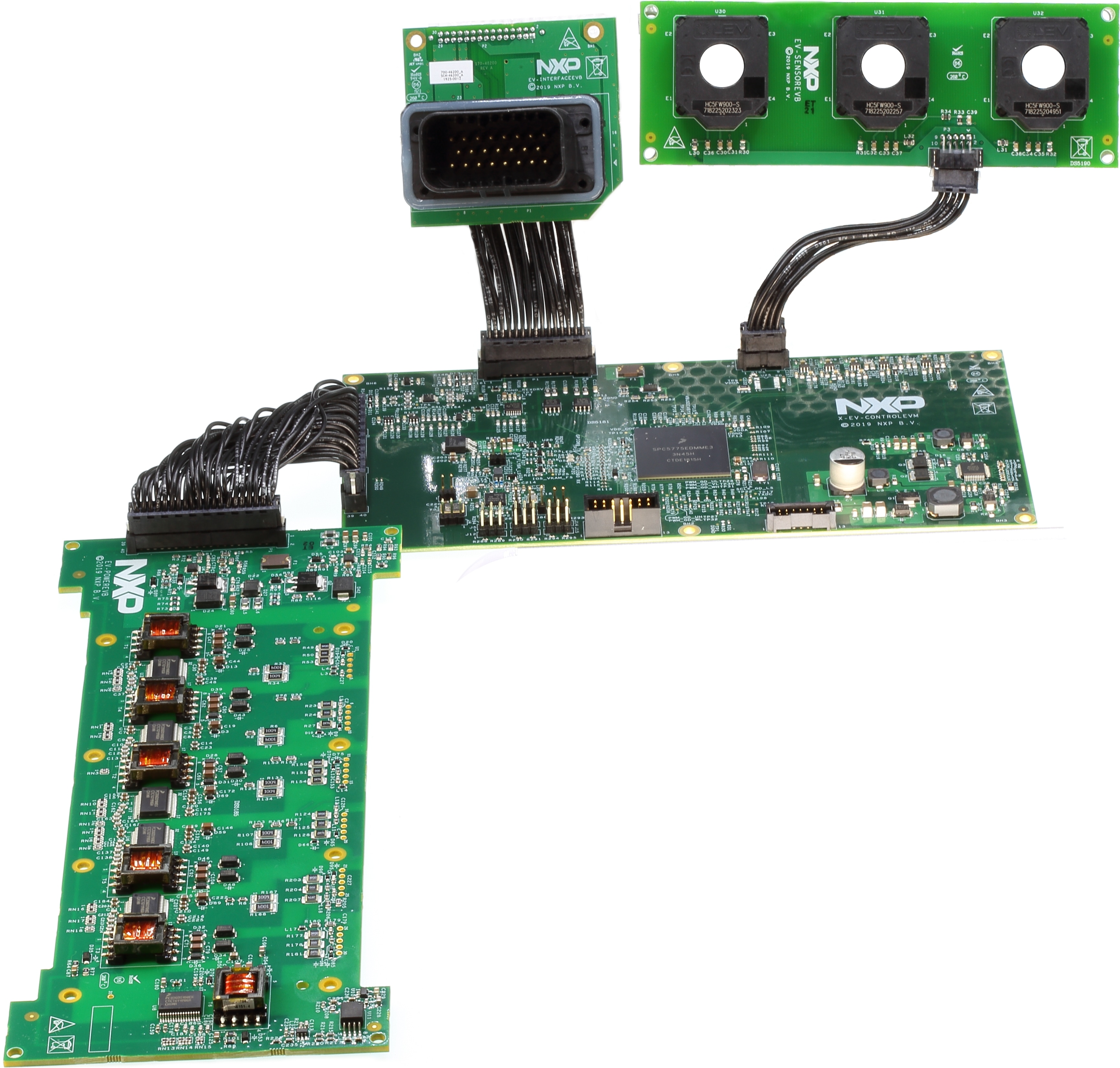
1.1 Kit Contents and Packing List
The EV-INVERTER kit contents include:
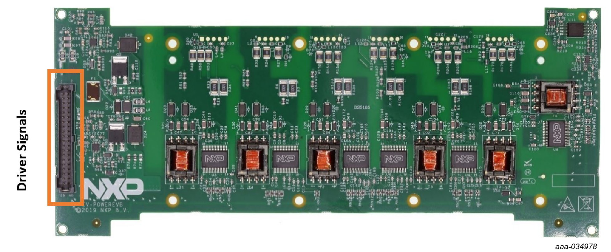
- Driver control board (EV-POWEREVB)
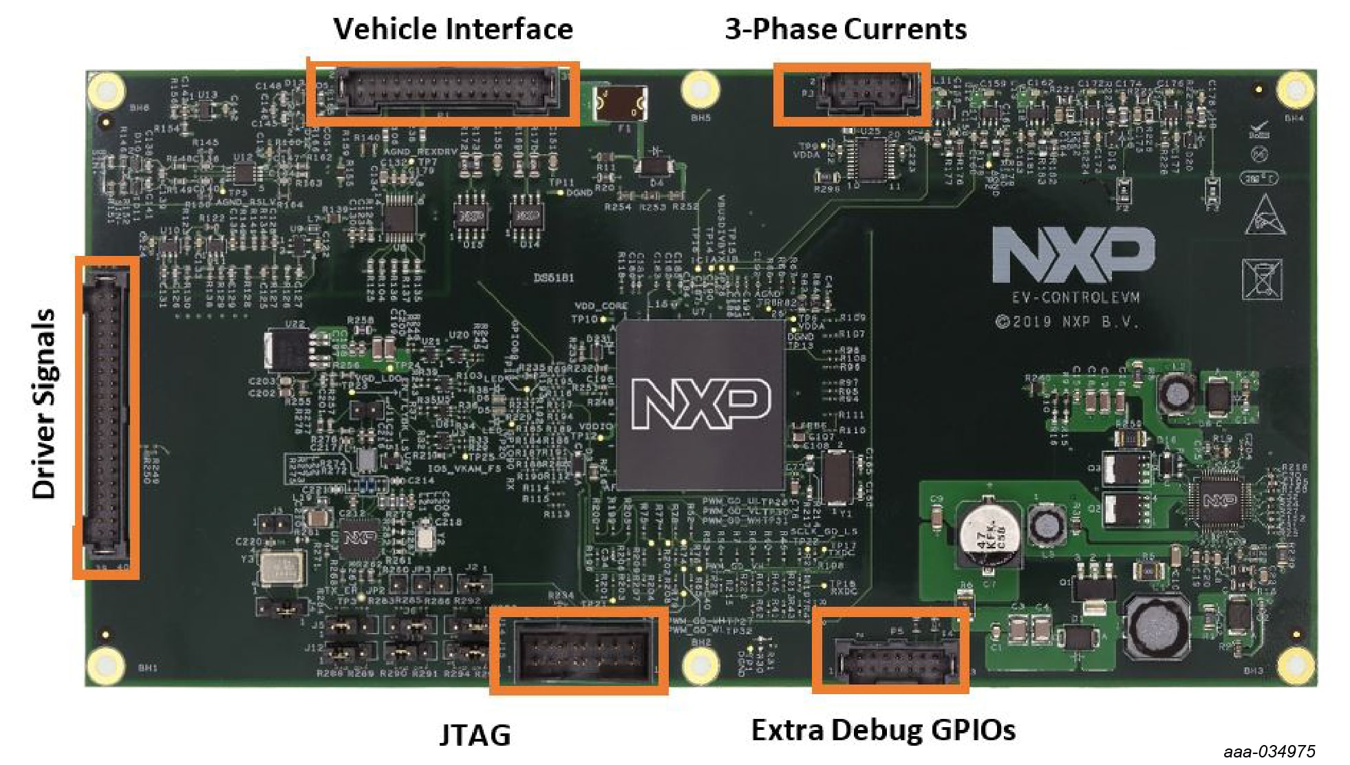
- MCU control board (EV-CONTROLEVM)
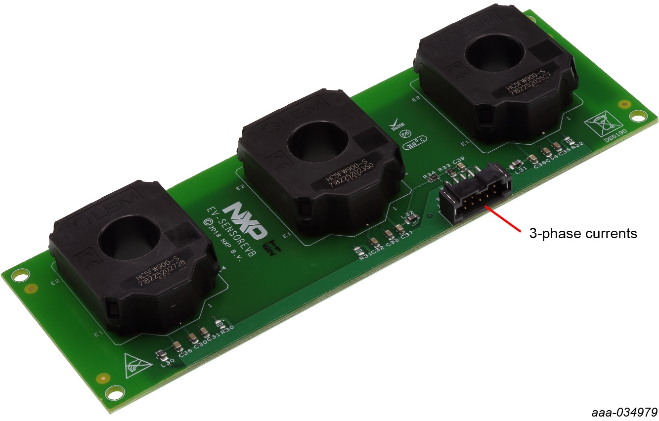
- Sensor board (EV-SENSOREVB)
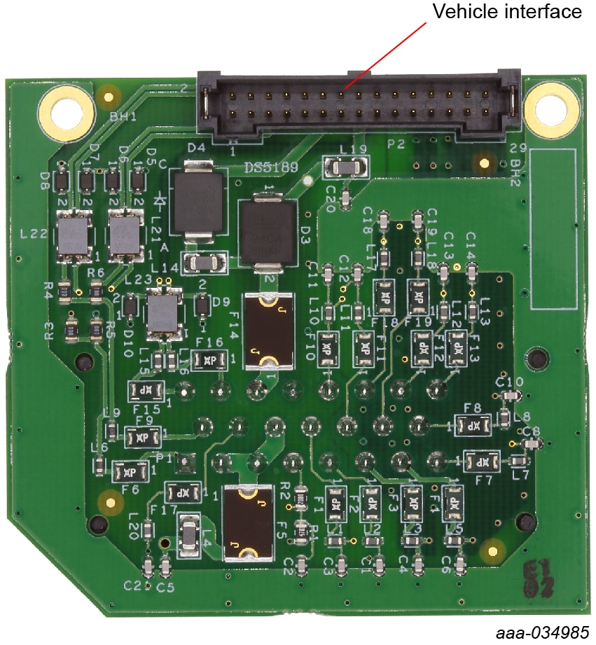
- Interface board (EV-INTERFACEVB)
-
Cables (EV-HW-INVERTER)
- –Cable assembly, double row wire cable, socket, double ended, 2×20, with retention latch, 4" length
- –Cable assembly, double row wire cable, socket, double ended, 2×15, with retention latch, 5.5" length
- –Cable assembly, double row wire cable, socket, double ended, 2×5, with retention latch, 4" length
- Quick start guide (HV Inverter platform)
1.2 Additional Hardware
In addition to the kit contents, the following hardware is necessary or beneficial when working with this reference platform. A complete EV Inverter Platform can be purchased from our development partner Vepco Technologies.
- FujiIGBTM653 module: available for purchase from Fuji Electric, Inc. by authorized customers of the NXP EV Inverter enablement kit.
- Cooling plate or water jacket for IGBT Fuji IGBTM653 module: the cold plate serves as the cooling structure interface for the IGBT module and it functions as mechanical support to the Power Inverter module (PIM) electronics and accessory components. Provide a cooling plate of your own design or purchase the complete platform from our inverter partner Vepco Technologies.
- DC link capacitor: four EZP-E50117MTA 500 V 110 µF film capacitors connected in parallel are used for inverter baseline performance measurements. Selected capacitor must be compatible with the IGBT listed above and intended operating voltages.
- Busbar: provide your own design or available when purchasing the complete platform from Vepco Technologies.
- High-voltage cabling: provide your own or available when purchasing the complete platform from Vepco Technologies
- 23-position signal connector: (Ampseal®PN 770680-1) TEConnectivity-770680-1
- Mounting hardware: provide your own or available when purchasing the complete platform from Vepco Technologies
- Power supply: up to 500 V, 400 A
- CAN interface link
- Motor: provide your own or available from Vepco Technologies
1.3 Windows PC Workstation
This reference platform requires a Windows PC workstation. Meeting these minimum specifications should produce great results when working with this reference platform.
- Windows 10, 8 or 7 compatible PC with an available USB port
2. Get Hardware
2.1 Board Features
Benefits:
- Increases speed of development
- Full platform solution
- Provides functional safety options
- Optimizes performance
Featured products:
- GD3100 isolated IGBT ASIL D gate driver
- MPC5775E advanced motor control ASIL D MCU
- FS65XX robust ASIL D SBC
- TJA1042 redundant CAN bus interface
- Capability to connect to Fuji M653 IGBT module for three-phase evaluations
2.2 Board Description
The EV-INVERTER is a reference design enablement kit containing NXP content to develop an EV three-phase traction motor inverter. The system is designed to drive the Fuji M653 IGBT module. This kit includes four PCBs as described in Section 1.1 "Kit contents/packing list", three cables used to interconnect the PCBs and basic configuration and drive software. PCB board layout and schematics and gerber files are available at EV Power Inverter Platform.
It is your responsibility to obtain the additional inverter components. These components include the IGBT module, link capacitor, bus bar, cooling plate, mounting hardware, etc.
You can design, select and assemble your own components and use the NXP PCBs to complete a PIM. A complete pre-assembled reference PIM platform is available through our partner Vepco Technologies. The IGBT module is available from our partner Fuji Electric.
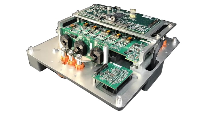
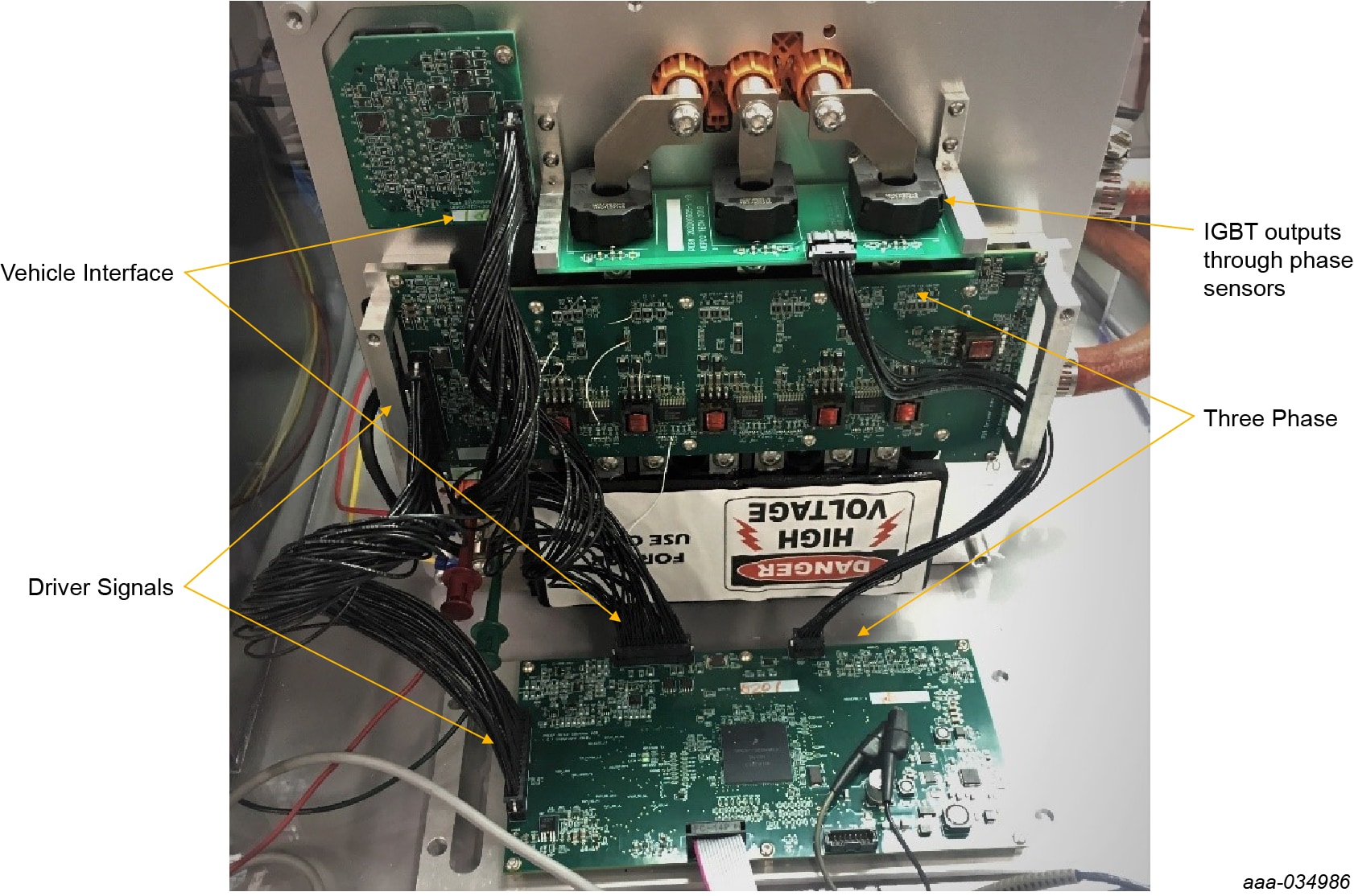
2.3 Board Components
Overview of the EV Power Inverter Control Reference Platform
3. Configure Hardware
3.1 Configure the Hardware
To configure the hardware, complete the following procedure:
- Attach the IGBT module to the cooling plate
- Attach the DC link capacitor positive and negative high-voltage supply
- Attach the EV-POWEREVB to the IGBT module. Ensure that all board socket connection pins are properly seated onto the IGBT pin connections
- Connect the motor to the IGBT module, ensuring the U, V, and W connections match
- For running a motor in a closed loop motor control, connect the EV-SENSOREVB board to the EV-CONTROLEVM
- Connect the EV-POWEREVB to the EV-CONTROLEVM
- Connect the EV-INTERFACEVB to the EV-CONTROLEVM
- Connect the low-voltage DC power supply to the EV-CONTROLEVM board
- Connect the high voltage/high current DC supply positive and negative connections on the DC Link capacitor to supply three-phase motor DC link voltage
- Before applying high voltage (>300 V) to the DC connection, use a current limited (1.0 A) power supply and apply 15 to 30 V to the DC to make sure that there is no excessive leakage current
- Unlatch the handle, insert the cable assembly to the header and relatch the handle. 12.Connect the EXT_DGND to 12 V GND
- Open the PIM by removing the plastic protection cover
- Connect the 14-pin debugger header with pin 1 mark aligned
- Both LED lights on the P&E micro Multilink should be On
4. Install Software Tools
4.1 S32S Design Studio IDE for Power Architecture
The S32S design studio for power architecture IDE installed on a Windows PC workstation enables editing, compiling and debugging of source code designs.
Install revision: Rev 2017.R1
- The IDE installer is available for download at: S32 Design Studio for Power Architecture® | Design Tools
- Installation instructions and related documentation is available at: S32 Design Studio for Power Architecture® | Documentation
- Additional information is available on the Product Release Announcement. S32 Design Studio for Power Architecture
4.2 Software Development Kit (SDK)
S32 SDK for Power Architecture RTM 3.0.0 supports MPC577x-B-E-C devices.
- The S32 Design Studio for Power Architecture SDK is available for download at: S32 Design Studio for Power Architecture® | Design Tools
- Installation instructions and additional information is available on the Product Release Announcement. S32 Design Studio for Power Architecture® | Documentation
- Additional information is available on the Product Release Announcement. S32 Design Studio for Power Architecture
4.3 Python Setup
- Download Python 3.6.8 from: Python
- Run the installer and follow the prompts to install it
- Open a command window and navigate to the install directory. To change the directory to Script, enter cd command
- Install PYQT5 by typing pip install pyqt5 and press Enter
- Install PYQTGraph by typing pip install pyqtgraph and press Enter
- Download the PIM GUI
- Unzip
c55_gui.zipto a folder that you want to run it from - Right-click on
app_mpc55term.pyand select Open with - Select Choose another app
- Scroll down and click More apps
Design Resources
Additional Resources
In addition to our EV Power Inverter Control Reference Platform page, you may also want to visit:
Product pages:
- MPC5775B and MPC5775E Microcontrollers for Battery Management Systems (BMS) and Inverter Applications
- GD3100: Advanced single-channel gate driver for Insulated Gate Bipolar Transistors (IGBTs/SiC)
- FS6500: Grade 1 and Grade 0 safety power system basis chip with CAN flexible data transceiver
- TJA1042: High-speed CAN transceiver with standby mode
Application pages:
Hardware pages:
Software pages:
Tool Summary Page
The tool summary page for EV-INVERTER reference platform is at EV Power Inverter Control Reference Platform.
The page provides overview information, technical and functional specifications, ordering information, documentation, and software. The Get Started provides quick-reference information applicable to using the EV-INVERTER reference platform, including the downloadable assets.