Getting Started with GreenBox 3 Real-Time Development Platform
Contents of this document
-
Out of the Box
-
Powering on GreenBox 3
-
Under the Hood
Sign in to save your progress. Don't have an account? Create one.
Purchase your GreenBox 3 Real-Time Development Platform
1. Out of the Box
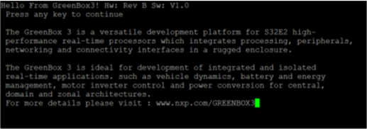
GreenBox 3 is a versatile development platform for the S32Z and S32E high-performance real-time processors which integrates processing, peripherals, networking and connectivity interfaces in a rugged enclosure. The GreenBox 3 is ideal for development and demonstrations of integrated and isolated real-time applications, for domain and zonal control, safety processing and vehicle electrification.
1.1 Get to Know GreenBox 3
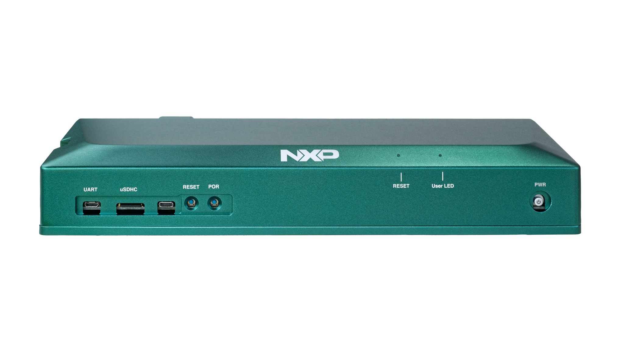
Pictured are the front panel connectors of GreenBox 3. These connectors will be used to help get started with GreenBox 3 with more details in the next section. The main featured processor of GreenBox 3 is the S32E288, which is a part of the S32E processor family.

2. Powering on GreenBox 3
Upon unpacking GreenBox 3, please notice that there is an SD card already inserted in the front panel connector labeled "uSDHC" slot. The SD card contains the basic software project that performs the minimum initialization to boot all of the cores of the S32E288 processor, communicates through UART with a host PC and toggles a GPIO pin to blink the User LED, which is also featured on the front panel connector of GreenBox 3.
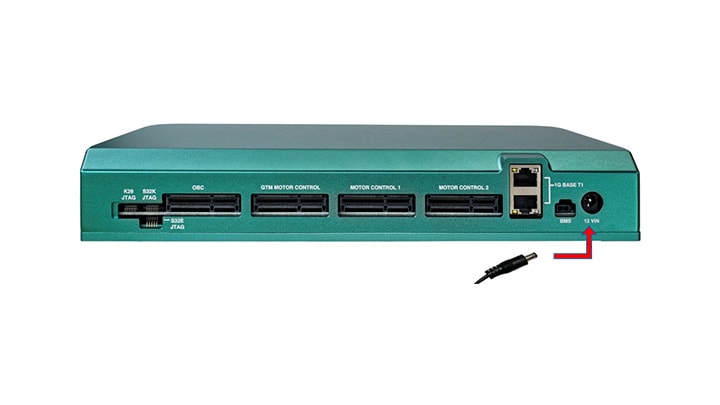
2.1 Connect Power Supply
Also included with the shipping components of GreenBox 3 is a 12 V DC power supply. Connect the board with the 12 V DC power supply as shown below. Please keep the board powered off for now.
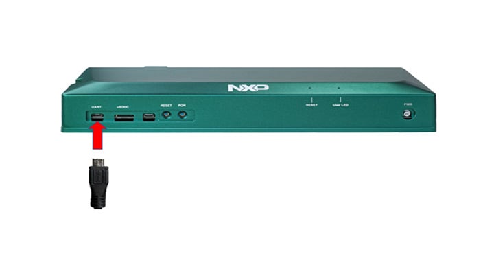
2.2 Connect USB Cable
On the front side of GreenBox 3 take one end of the USB cable and insert it into the "UART" connector. Take the other end of the USB cable and insert it into your PC.
2.3 Start Preferred Serial Terminal
Install and open any serial communication terminal. Configure the terminal to be:
- 115200 Baud Rate
- 8 data bits
- No parity
- One stop bit
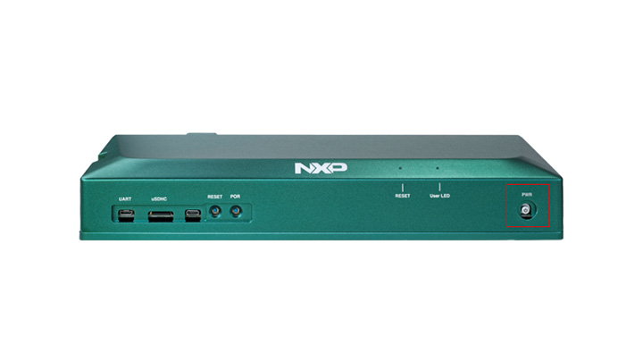
2.4 Power on the Device
Power on the device by pressing the PWR button.
3. Under the Hood
Contained in the GreenBox 3 chassis is the printed circuit board (PCB). To access the PCB, jumper settings and additional peripherals, use a hex/allen key to remove the four screws on the bottom of the chassis. Once unscrewed, access to the entirety of GreenBox 3 is allowed.
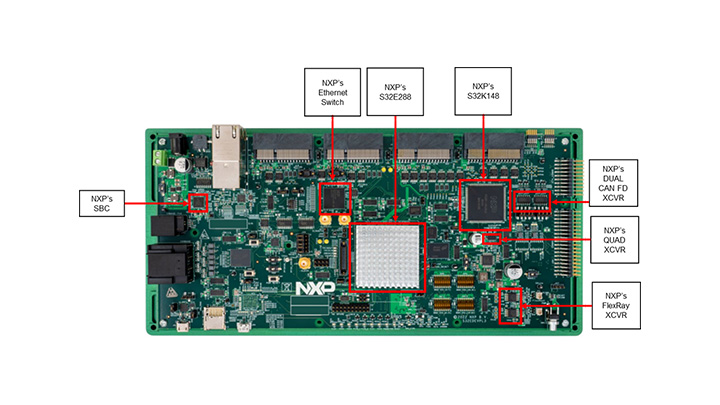
3.1 GreenBox 3 PCB
There are many integrated circuits (IC) featured in GreenBox 3. Each provides a specific purpose to allow easy development with GreenBox 3. For more in depth information about the additional ICs, jumper descriptions, software access and additional peripherals, please refer to the GreenBox 3 user manual.
Virtual COM Port Enablement
Virtual COM Port Enablement
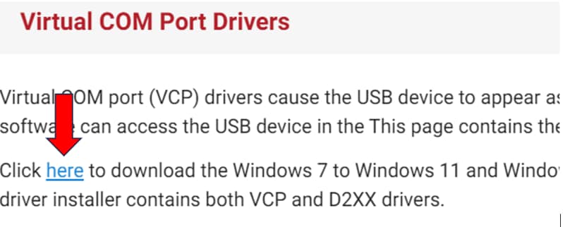
This step is only needed if you discovered your PC did not automatically configure or did not provide a COM port for the UART of GreenBox 3. If this is the first time you are using virtual COM ports, you need to configure your PC accordingly. Use the following link:
Virtual COM Port DriversFollow the necessary steps when prompted from the installer.
Installing Serial Terminal
Installing Serial Terminal
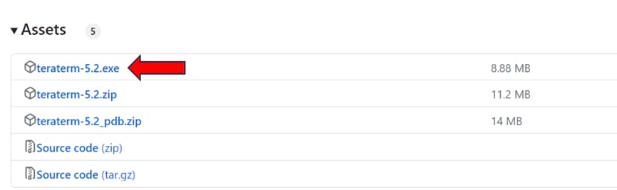
This step is only needed if you discovered your PC did not automatically configure or did not provide a COM port for the UART of GreenBox 3. If this is the first time you are using virtual COM ports, you need to configure your PC accordingly. Use the following link: Download Serial Terminal
Follow the necessary steps when prompted from the installer.
Design Resources
Support
Forums
Connect with other engineers and get expert advice on designing with theGreenBox 3 Real-Time Development Platform using our suggested sites.