Getting Started with the DEVKIT-MPC5748G
Contents of this document
-
Out of the Box
-
Get Software
-
Plug It In
-
Create, Build and Load
Sign in to save your progress. Don't have an account? Create one.
Purchase your MPC5748G Secure Gateway Development Board
1. Out of the Box
Applies for the DEVKIT-MPC5748G evaluation board REV D.
The DEVKIT-MPC5748G REV D has several improvements:
- Latest MPC5748G silicon used (mask set 0N78S)
- Added MicroSD connector for SDHC access
- MicroUSB connector replaced with full-size connector for easier use with USB devices
- Alternative placement of JTAG header and power supply jumper for easier access when using shields
DS4changed to red andDS5changed to orange- Added pre-soldered pull resistor on
CAN0interface, which can be added or removed withJ16 - Shorter array of female pin headers, allowing for smaller form factor
- Fixed issue with USB
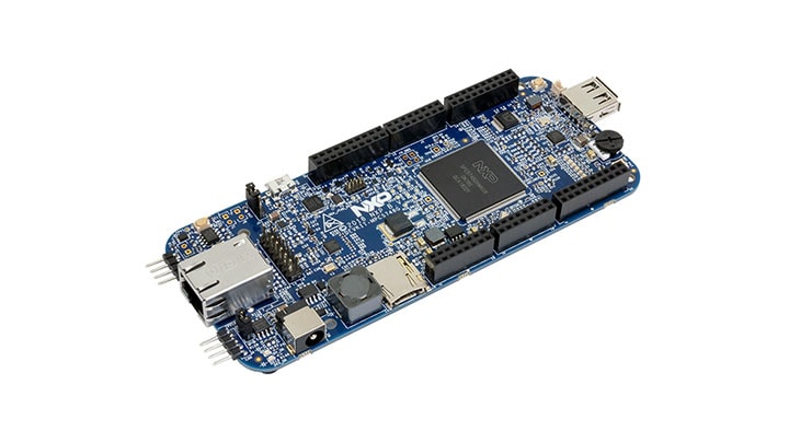
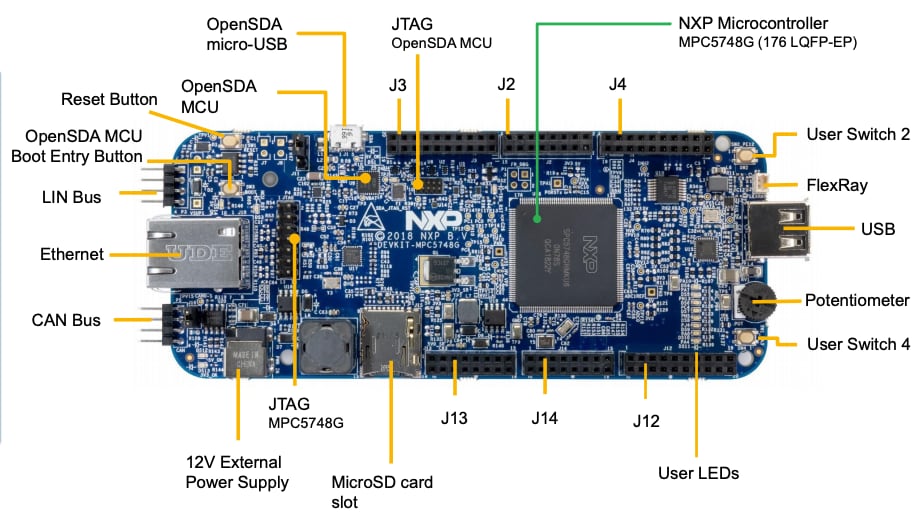
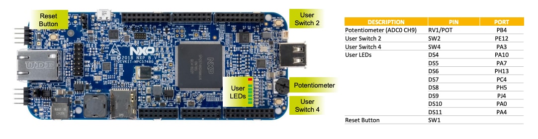
1.1 Get to Know Your Evaluation Board
DEVKIT-MPC5748G evaluation board REV D.
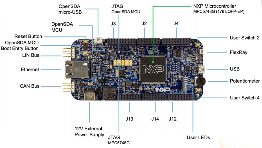
DEVKIT-MPC5748G evaluation board REV B.
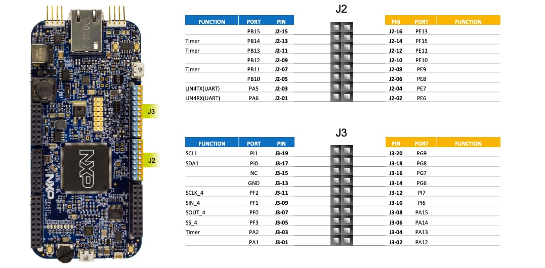
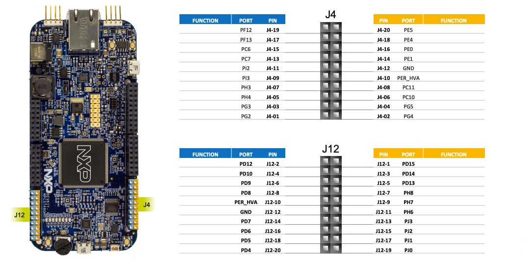
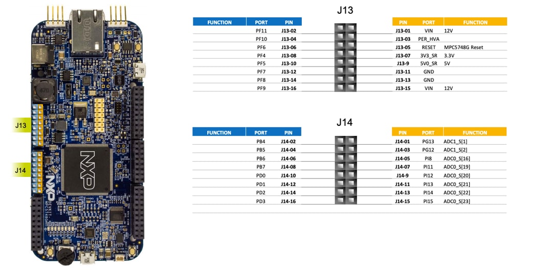
1.2 Understanding the Header/Pinout
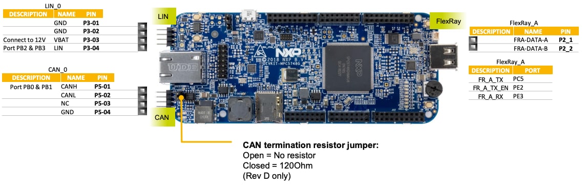
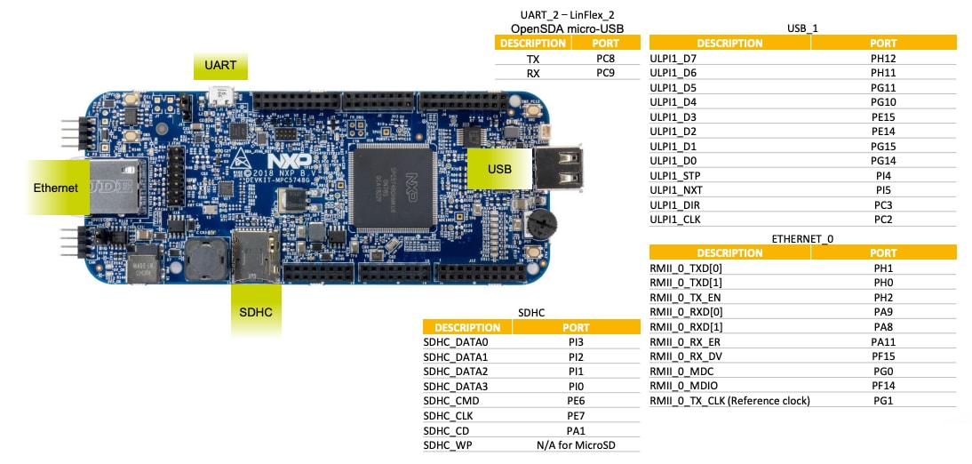
1.3 Understanding Interfaces
The communication interfaces for DEVKIT-MPC5748G evaluation board:
The programming interfaces for DEVKIT-MPC5748G evaluation board:
1.4 Understanding Peripherals
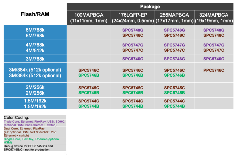
1.5 Understanding MPC574xG/C/B/D Family Differences
1.6 General Recommendations
- For high power/current consuming applications (like using external shield boards) use "External 12 V Supply" only
-
External 12 V supply specifications:
- Fully regulated switching power supply
- Input voltage: 100-240 V AC 50/60 Hz
- Output: 12 V 1 A/2 A DC
- Plug size: 5.5 mm x 2.1 mm, center positive
- By default, "New Project" in S32 Design Studio IDE makes the application run at 16 MHz internal RC (IRC) oscillator. For faster performance, configure PLL to desired frequency and switch clock source to PLL before executing application code
- For faster debugging, debug from RAM, because this cuts down the lengthy flash erase operation cycles. Follow the Software Integration Guide (SWIG) for details
- Keep both S32 Design Studio IDE and OpenSDA firmware up to date for best results
2. Get Software
2.2 Get the Integrated Development Environment (IDE)
S32K144EVB performs better when using S32 Design Studio for Power Architecture®.
- The installation will requires Microsoft Visual C++ 2013 package. If libraries are already installed, a "Modify Setup" dialog box appears with the requirement "Repair"
- When asked for "Activation ID", copy and paste it from the "Download" page and select an online activation
- During the Installation, it may ask you to install P&E device drivers
2.3 Get the PC Configuration Driver
Some example applications output data over the MCU UART, so make sure that the driver for the board's virtual COM port is installed.
To view the serial output from the MCU’s UART, run your preferred terminal application once the serial port driver is installed. Configure the terminal to 57,600 baud rate, 8 data bits, no parity and 1 stop bit.
Learn more about Using a Terminal Application at Projects and Tutorials section.
3. Plug It In
Watch the video to set up your evaluation board. You can also use the step-by-step guide.
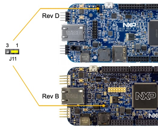
3.1 Set Up Jumpers in the Evaluation Board
The J11 is the only jumper. It helps select the power source:
1-2: Default external 12 V supply2-3: USB powered 5 V supply, through OpenSDA interface
Learn more about OpenSDA at Projects and Tutorials section.
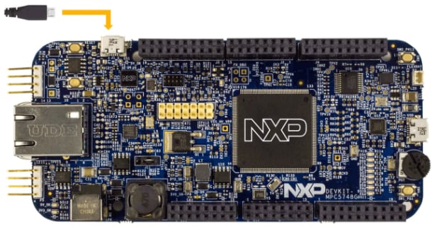
3.2 Plug the USB Cable
Connect one end of the USB cable to the PC and the other end to the micro-B connector on the DEVKIT-MPC5748G board. Allow the PC to automatically configure the USB drivers.
The pre-loaded example project utilizes the DEVKIT-MPC5748G user push button (SW2) and the user LEDs.
Once the board is plugged in, LEDs will blink in default pattern.
Press push button to switch between the two different patterns. Use potentiometer to change blinking speed.
4. Create, Build and Load
Let’s take it for a test drive. Watch the video to create a new project in S32 Design Studio IDE and load example code. You can also use the step-by-step guide.
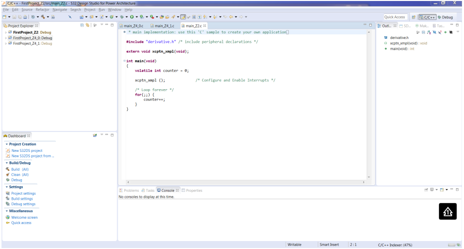
4.1 Create a New Project in IDE
-
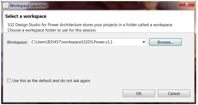
Launch the S32 Design for Power Architecture® and select a default workspace or specify a new one. Then click "OK"
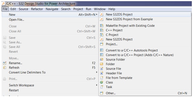
- Create a new project by selecting File → New → Project
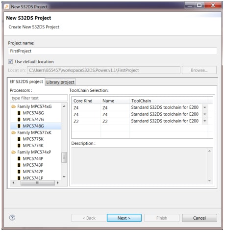
- Choose a project name and then select a project type, then click "Next". We recommend using
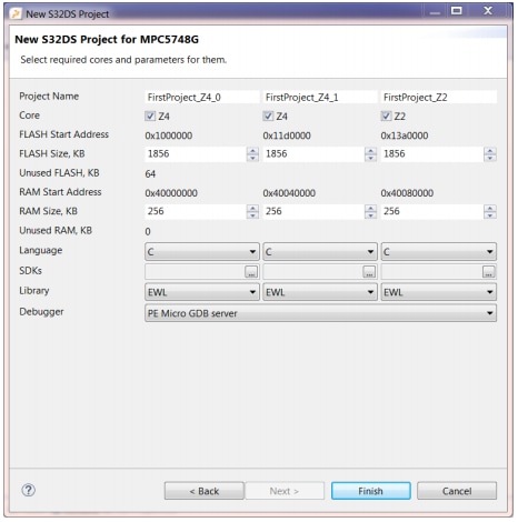
Elf S32DS Project - Select cores and parameter, then click "Finish". We recommend using the default settings. You can choose flash and RAM size and make selections in "Language", "Library" and "Debugger"
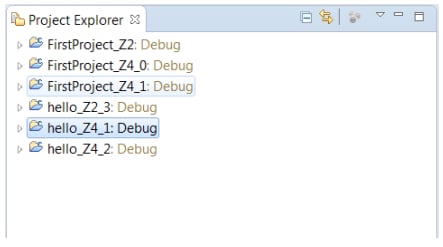
- Three projects will be created for three different cores of MPC5748G
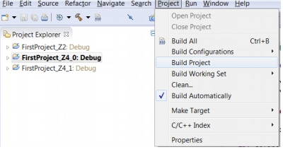
4.2 Build a New Project in IDE
Follow one of these paths to build a new project:
- Select Project → Build Project
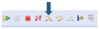
- To build the project, click the hammer icon

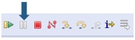
- To build all projects, click the paper and number icon

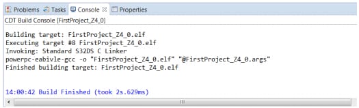
Once you have successfully built your project, the following message displays on the console:
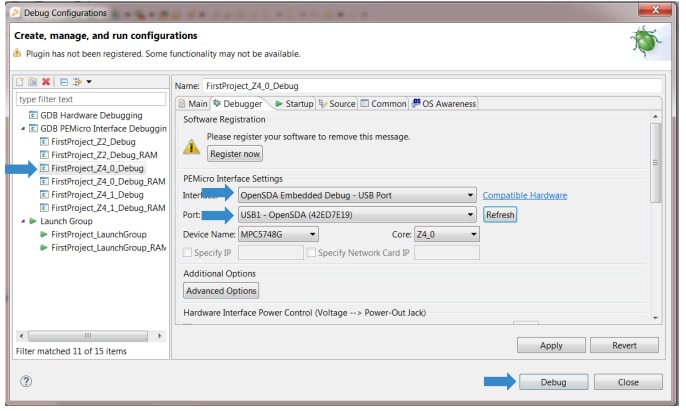
4.3 Debug a Project in IDE
-
Connect a debugger to both the board and the PC
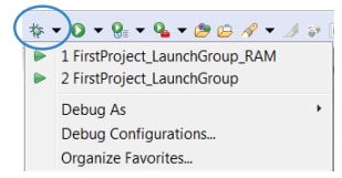
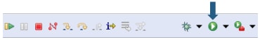
- Open "Debug Configuration" options in the top menu
-
Select a project and interface and then click "Debug"
(Example: "FirstProject_Z4_0_Debug" and "OpenSDA for DEVKIT-MPC5748G")
Learn more about Debug Basics at Projects and Tutorials section.
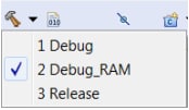
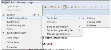
4.4 Debug a Project from RAM
To configure a project to debug from RAM, follow one of these paths:
- Go to Project → Build Configurations → Set Active → Debug_RAM
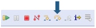
- To select Debug_RAM, click the arrow near the hammer icon
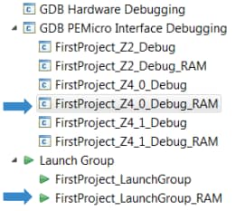
-
Finally, to debug from RAM, select the RAM-related session while debugging
4.5 Make Projects From Built-In Examples
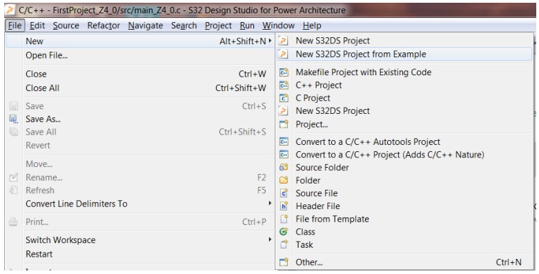
- Launch S32 Design Studio for Power Architecture, for example, go to File → New → New S32DS Project
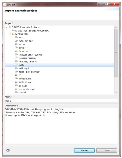
- Select the built-in project of your choice and click "Finish"
- The selected project will be copied to the active workspace
-
The DEVKIT-MPC5748G example codes also include the projects from AN4830: Qorivva Recipes for MPC574xG
- Hello
- Hello + pll
- Hello + pll + interrupts
- eDMA + PBridge
- Semaphores
- Register Protection
- Low Power: STOP mode
- Analog-to-digital converter
- Timed I/O (eMIOS)
- CAN
- CAN + DMA
- LIN
- UART
- SPI
- SPI + DMA
- I2C
- Ethernet
- Body Cross Trigger Unit (BCTU)
- System Memory Protection Unit (SMPU)
- Flash
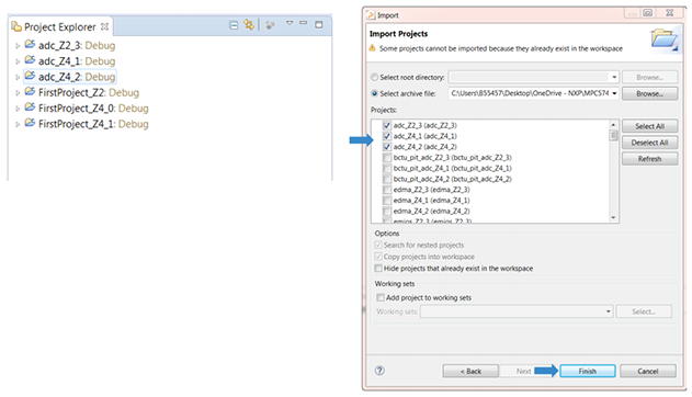
4.6 Import Projects into IDE
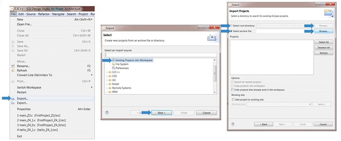
- Go to File → Import and click "Existing Projects" into the workspace option. Then click "Next"
- Browse and select an example folder
- Select a project. To import it into the workspace, click "Finish"
Using a Terminal Application
Tera Term Tutorial
Tera Term is a very popular open source terminal emulation application. This program can be used to display information sent from your NXP® development platform's virtual serial port.
- Download Tera Term from SourceForge. After the download, run the installer and then return to this webpage to continue
-
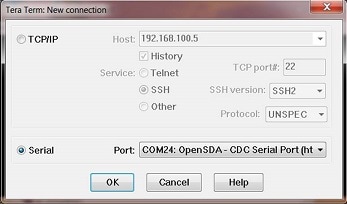
Launch Tera Term and select the Serial option
- Using the COM port number identified earlier, configure serial port settings to 57,600 baud rate, 8 data bits, no parity and 1 stop bit. Go to Setup → Serial Port and update the settings
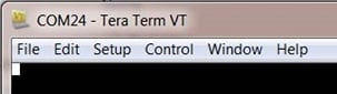
- Verify that the connection is open. Once connected, Tera Term will update its title bar:
- You are ready to go
PuTTY Tutorial
PuTTY is a popular terminal emulation application. This program can be used to display information sent from your NXP development platform's virtual serial port.
- Download PuTTY and run the installer
- Launch PuTTY
-
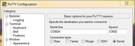
Configure the Serial radio button and enter the COM port number you determined earlier. Also, enter the baud rate
-
Open the serial connection
- You are ready to go
Debug Basics
Debug Basics
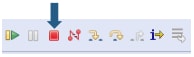
Step, Run, Suspend, Resume and Terminate
-
Step Into (F5)
-
Step Over (F6)
-
Run
-
Suspend
-
Resume (F8)
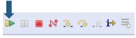
-
Terminate (Ctrl + F2)
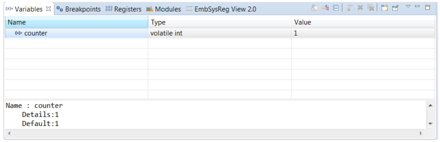
View Variables
- Click the "Variables" tab. To enter different values, click in the "Value" field
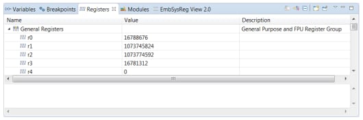
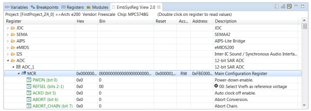
View and Alter Registers
- To see CPU registers, click the "Registers" tab. To enter different values, click in the "Value" field
- To view peripheral registers, go to the "EmbSysReg" tab
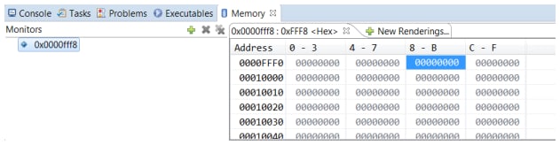
View Memory
- To add a memory monitor, click the plus icon (+) and select a base address
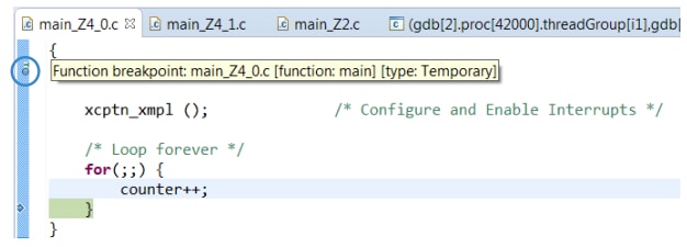
Breakpoints
- To add breakpoints, place your cursor and double click
Introduction to OpenSDA
OpenSDA is an open-standard serial and debug adapter. It bridges serial and debug communications between a USB host and an embedded target processor.
The DEVKIT-MPC5748G comes with the OpenSDA application preinstalled. Follow these instructions to run the OpenSDA Bootloader and update or change the installed OpenSDA application.
| Enter OpenSDA Bootloader Mode | Load an OpenSDA Application |
|---|---|
A removable drive should now be visible in the host file system with a volume label of BOOTLOADER. You are now in OpenSDA Bootloader mode. |
Use the same procedure to load other OpenSDA applications. |
Note: Follow the "Load an OpenSDA application" instructions to update the application on your MK20DX128VFM5 to the latest version. It is likely that the version provided in this package is newer than what was preprogrammed on your MK20DX128VFM5.
Using the Virtual Serial Port
Determine the symbolic name assigned to the EVB-S32K144 virtual serial port
In Windows, open Device Manager and look for the COM port named
OpenSDA-CDC Serial Port-
Open the serial terminal emulation program of your choice
- Program one of the "code examples" using S32 Design Studio IDE
- Configure the terminal emulation program. Most embedded examples use 8 data bits, no parity bits and one stop bit (8-N-1). Match the baud rate to the selected serial test application and open the port
- Press and release Reset (
SW1) at any time to restart the example application. Resetting the embedded application will not affect the connection of the virtual serial port to the terminal program
Note: Refer to the OpenSDA User's Guide for a description of a known Windows issue when disconnecting a virtual serial port while the COM port is in use.
Design Resources
Board Documents
Chip Documents
- MPC574xG – Data Sheet
- MPC574xG – Reference Manual
- MPC574xG MCUs– Functional Safety Documentation (requires access to the SafeAssure NDA group)
Support
Forums
Connect with other engineers and get expert advice on designing with the DEVKIT-MPC5748G on one of our community sites.
On this page
- 1.1
Get to Know Your Evaluation Board
- 1.2
Understanding the Header/Pinout
- 1.3
Understanding Interfaces
- 1.4
Understanding Peripherals
- 1.5
Understanding MPC574xG/C/B/D Family Differences
- 1.6
General Recommendations
- 2.1
Download Software Examples
- 2.2
Get the Integrated Development Environment (IDE)
- 2.3
Get the PC Configuration Driver