Contents of this document
-
Build the Setup
-
Get Software
-
Create, Build, and Debug
Sign in to save your progress. Don't have an account? Create one.
Purchase your MicroSys Miriac™ EK5744 Funcional Safety Evaluation Kit
1. Build the Setup
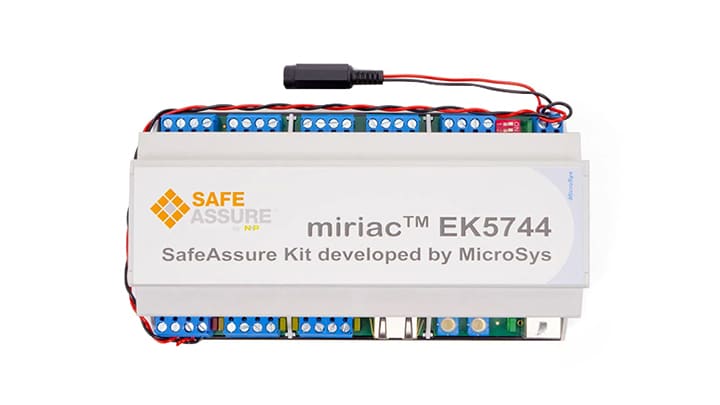
Getting Started with Miriac™-EK5744 Functional Safety Kit.
The Miriac™-EK5744 is an MPC5744P-based functional safety kit from NXP, built in partnership with Microsys. The kit features a safety-oriented design approach that includes features like hardware redundancy and fail-safe mechanisms. You can use this hardware design for your own safety system. Let's take your Miriac-EK5744 for a test drive! You have the choice of watching a short setup video or following the detailed actions listed below.
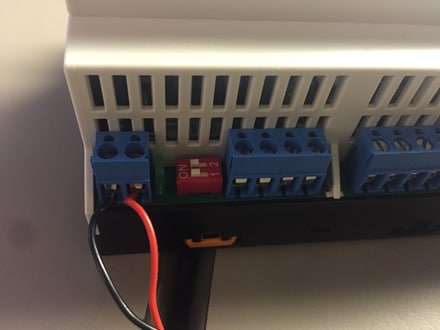
1.1 Connect Power to the Kit
The Miriac-EK5744's processor and SBC are powered through the ports shown in the figure below. Use a flathead screwdriver to fasten two leads to the terminal. Ground goes on the left and a 12-24V input supply goes to the right. 20V is the optimal supply voltage to see full functionality. You can use a power adapter or a DC power supply.
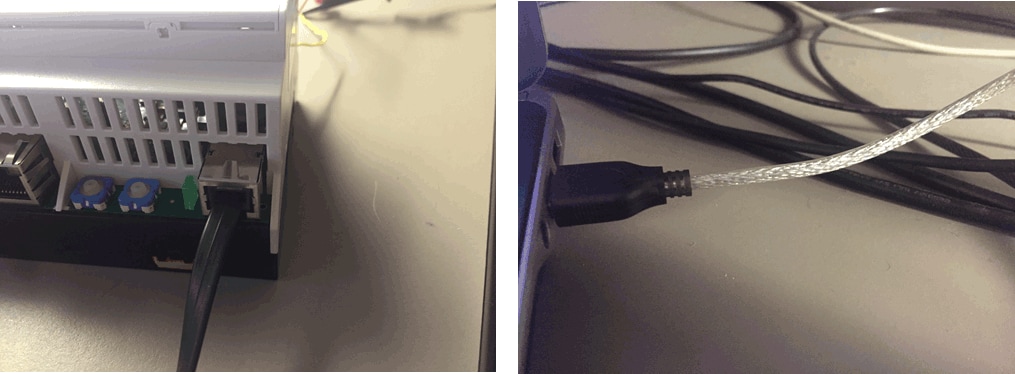
1.2 Plug in the UART
Plug in a USB adapter to the UART terminal and the USB to a computer. This connection allows the Miriac-EK5744 to display console messages to your computer.
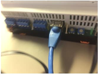
1.3 Plug in the Ethernet
The Miriac-EK5744 requires a DHCP (Dynamic Host Configuration Protocol) connection. Plug in a network-enabled ethernet adapter to the ethernet port. The out-of-box firmware will proceed if it detects an IP address.
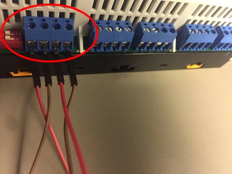
1.4 Wire the CAN Ports
Connect the two CAN ports together, CAN_L to CAN_L and CAN_H to CAN_H as in the image below. Also make sure the CANs switches next to the CAN terminals are in the ON position.
1.5 Find your COM Port
Load the device manager and find the COM port that the Miriac-EK5744 occupies on your computer. The COM port number will vary with each PC.
1.6 Load Your COM Port Into a UART Terminal
Connect the COM port to a UART terminal such as PuTTY or Tera Term. Use the baud rate 115200. Refer to these tutorials for installation instructions: Tera Term Tutorial, PuTTY Tutorial.
1.7 Observe the Output
Watch the Miriac-EK5744 print status messages. The out-of-box firmware, among other tests, checks for an IP connection, tests the CAN ports, and reports SBC temperature. The firmware tests repeat indefinitely.
2. Get Software
2.1 Jump-Start Your Design by Downloading Miriac-EK5744 Quick Start Package
Download Quick Start Guide and sample software to kickstart your design.
Get Miriac-EK5744 Quick Start Package2.2 Install Your Toolchain
NXP offers a complimentary toolchain called S32 Design Studio (S32DS). The S32 Design Studio is an Eclipse-based IDE that offers comprehensive software writing and debugging capabilities. It supports multiple debuggers including GDB and Lauterbach.
Get S32 Design Studio IDE3. Create, Build, and Debug
Learn how to create a new project in S32 Design Studio IDE for Power Architecture and the basics to create your own code by running an easy example code.
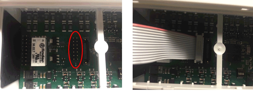
3.1 Disable the Watchdog
Short the debug jumper shown in the figure below. This makes the Miriac™-EK5744 ignore watchdog requests.

3.2 Plug in the Debugger
The Miriac-EK5744 supports debug through JTAG. Plug in a JTAG connector to the JTAG port in the orientation shown in the figure. NXP recommends the P&E Micro USB Multilink or Lauterbach.
3.3 Create, Build, and Debug Your Application
Software Integration Guide(SWIG) in the Quick Start Package provides easy, step-by-step instructions on how to create, build, and debug projects. Alternatively you can download SWIG from the link below.
Software Integration Guide3.4 Explore the Example Code
For your convenience, we integrated example code in to S32 Design Studio for Power Architecture. Alternatively they can be found in to Quick Start Package. Again Software Integration Guide(SWIG) provides step-by-step instructions on "How to use?".
Tera Term Tutorial
Tera Term Tutorial
Tera Term is a very popular open source terminal emulation application. This program can be used to display information sent from your NXP development platform's virtual serial port.
- Download Tera Term from link below. After the download, run the installer and then return to this webpage to continue.
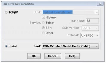
- Launch Tera Term. The first time it launches, it will show you the following dialog. Select the serial option. Assuming your board is plugged in, there should be a COM port automatically populated in the list.
- Configure the serial port settings (using the COM port number identified earlier) to 115200 baud rate, 8 data bits, no parity, and 1 stop bit. To do this, go to Setup → Serial Port and change the settings.
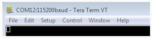
- Verify that the connection is open. If connected, Tera Term will show something like below in its title bar.
- You're ready to go.
PuTTY Tutorial
PuTTY Tutorial
PuTTY is a popular terminal emulation application. This program can be used to display information sent from your NXP development platform's virtual serial port.
- Download PuTTY using the button below. After the download, run the installer and then return to this webpage to continue.
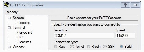
- Launch PuTTY by either double-clicking on the *.exe file you downloaded or from the Start menu, depending on the type of download you selected.
- Configure In the window that launches, select the Serial radio button and enter the COM port number that you determined earlier. lso enter the baud rate, in this case 19200.
- Click Open to open the serial connection. Assuming the board is connected and you entered the correct COM port, the terminal window will open. If the configuration is not correct, PuTTY will alert you.
- You're ready to go.
On this page
- 1.1
Connect Power to the Kit
- 1.2
Plug in the UART
- 1.3
Plug in the Ethernet
- 1.4
Wire the CAN Ports
- 1.5
Find your COM Port
- 1.6
Load Your COM Port Into a UART Terminal
- 1.7
Observe the Output
- 2.1
Jump-Start Your Design by Downloading Miriac-EK5744 Quick Start Package
- 2.2
Install Your Toolchain