Getting Started with the FRDMSTBANBP8XD Freedom Shield Evaluation Board
Contents of this document
-
Get Started
-
Get to Know the Hardware
Sign in to save your progress. Don't have an account? Create one.
Purchase your NBP8 FRDM Shield Evaluation Board
1. Get Started
This page will guide you through the process of setting up and using the FRDMSTBANBP8XD board.
1.1 Kit Contents/Packing List
The FRDMSTBANBP8XD contents include:
- FRDMSTBANBP8XD shield board with Arduino headers
- Quick Start Guide
1.2 Additional Resources
The FRDMSTBANBP8XD can be paired with a variety of NXP MCU boards. However, an evaluation project is available to customers who select the FRDM-KE15Z board.
1.3 User Manual
Refer to UM11568, FRDMSTBANBP8XD shield board for additional details on the featured components and board configuration.
2. Get to Know the Hardware
2.1 Board Description
The FRDMSTBANBP8XD shield board incorporates an NBP8FD fully integrated battery pressure monitor sensor that offers:
- a small footprint in a 4 x 4 mm package
- low power consumption
- SPI
- ready/interrupt
- power supply enable capabilities
The FRDMSTBANBP8XD shield board can be easily connected to an NXP FRDM MCU board via the Arduino headers for evaluation. The FRDM-KE15Z board is recommended.
Users can connect the two boards to evaluate the NPB8XD battery pressure monitor sensor by using either a terminal program and commands or a demo GUI. In either case, the hardware facilitates software development.
These boards provide an intuitive way to change the interrupts, PWM (if available), and power supply enable signals for specific pin configurations. The board also contains test points that are typically used for evaluation.
2.2 Board features
- Sensor add-on/companion boards feature battery pressure monitor sensor with capabilities compatible with the FRDM board ecosystem
- Compatible with Arduino® and most NXP FRDM development boards
- Allows evaluation of current consumption and pin voltage characteristics
- Supports SPI communication interface with host MCU
- Supports hardware configurability to switch PWM output (NBP9 only)
- Support multiple test points on the board
2.3 Board Components
The FRDMSTBANBP8XD shield board comes with standard Arduino headers and can be paired and connected with NXP FRDM MCU boards for user evaluations and software development. For quick evaluation and prototyping, NXP provides a demo project targeted to the FRDM-KE15Z board and hardware design files that help reduce the time to market.
2.4 Configure the hardware
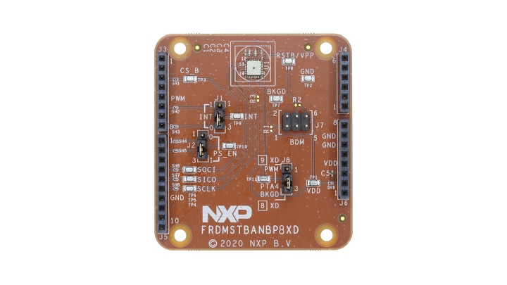
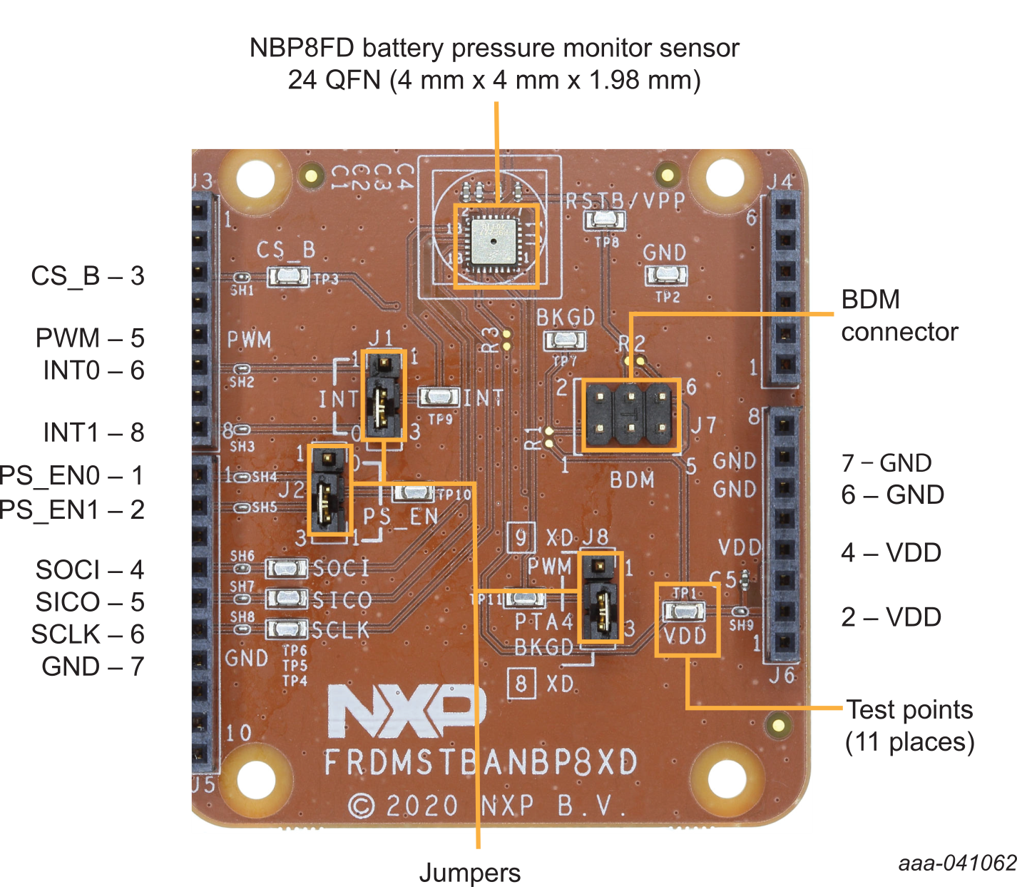
As shown in Figure 1, the following signals are available on the Arduino headers of the FRDMSTBANBP8XD shield board:
- The interrupt signals, INTx can be ported to either
J3-6orJ3-8by selector jumperJ1 - The power supply enable signal, PS_ENx can be ported to either
J5-1orJ5-2by selector jumperJ2 - The PWM signal (NPB9FD only) can be ported to
J3-5by selector jumperJ8, pins1-2. Note that the default setting is the BKGD signal (J8, pins 2-3) used to program U1 via the BDM port throughJ7. The SPI interface is provided throughJ3andJ5. These are:J3-3, CS_B, Client SelectJ5-4, SOCI, Server-Out-Client-In dataJ5-5, SICO, Server-In-Client-Out dataJ5-6, SCLK, SPI clock
- VDD is supplied through
J6-2/J6-4. This is typically supplied through a FRDM MCU board such as the FRDM-KE15Z - GND is supplied through
J6-6/J6-7. This is typically supplied through a FRDM MCU board such as the FRDM-KE15Z
Design Resources
Board Documents
- UM11568, Introduction to the FRDMSTBANBP8XD Shield Board - User Manual
- FRDMSTBANBP8XD Design Files
- FRDMSTBANBP8XD Schematics
Get Help
Forums
Connect with other engineers and get expert advice on designing with the FRDMSTBANBP8XD on one of our community sites.