Getting Started with the FS45XX/FS65XX Evaluation Boards
Contents of this document
-
Get Started
-
Get to Know the Hardware
-
Install Software
-
Configure the Hardware
Sign in to save your progress. Don't have an account? Create one.
Purchase your KITFS6523CAEEVM System Basis Chip
1. Get Started
The NXP analog product development boards provide an easy-to-use platform for evaluating NXP products. The boards support a range of analog, mixed-signal and power solutions. They incorporate monolithic integrated circuits and system-in-package devices that use proven high-volume technology. NXP products offer longer battery life, a smaller form factor, reduced component counts, lower cost and improved performance in powering state-of-the-art systems.
This page will guide you through the process of setting up and using FS45xx/FS65xx evaluation boards.
1.1 Kit Contents/Packing List
The kit contents include:
- Assembled and tested evaluation boards/modules in anti-static bag
- Connector, terminal block plug, 2 pos., str. 3.81 mm
- Connector, terminal block plug, 10 pos., str. 3.81 mm
- Cable, assy, USB-STD A to USB-B-mini 3.0 ft.
- Quick start guide
1.2 Additional Hardware
In addition to the kit contents, the following hardware is necessary or beneficial when working with this kit.
- Power supply with a range of 8.0 V to 40 V and a current limit set initially to 2.0 A
- Standard A plug to Mini-B plug USB cable
1.3 Windows PC Workstation
This evaluation board requires a Windows PC workstation. Meeting these minimum specifications should produce great results when working with this evaluation board.
- USB-enabled computer with Windows 7 or Windows 10
1.4 Software
Installing software is necessary to work with this evaluation board.
- FlexGUI graphical user interface available at FLEXGUI
- FlexGUI register definition XML file
2. Get to Know the Hardware
2.1 Board Features
- VBAT power supply either through power jack (2.0 mm) or phoenix connector
- VCORE configuration: 1.23 V, 3.3 V and 5.0 V
-
VCCA configuration:
- 3.3 V or 5.0 V
- Internal transistor or external PNP
- VAUX configuration: 3.3 V or 5.0 V
- Buck or boost setting
- DFS configuration
- Ignition key switch
- LIN bus (optional)
- CAN bus
- FS0B
- FS1B (option)
- IO connector (IO_0 to IO_5)
- Debug connector (SPI bus, CAN digital, LIN digital, RSTB, FS0B, INTB, Debug, MUX_OUT)
- Signalling LED to give state of signals or regulators
- KL25Z MCU installed on board for easy connection to host computer on USB link
2.2 Board Description
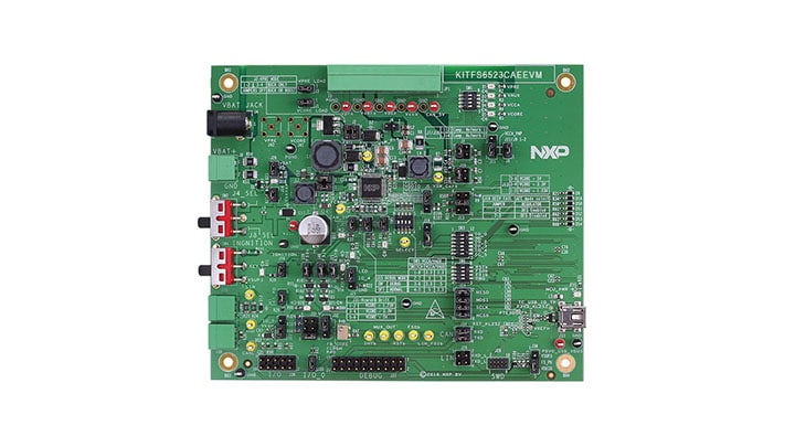
The KITFS4503CAEEVM, KITFS4508CAEEVM, KITFS6507LAEEVM, KITFS6522LAEEVM and KITFS6523CAEEVM are hardware evaluation tools supporting system designs based on NXP’s FS4500 and FS6500 product families. The kits allow testing the devices as an integral part of the overall system being developed. They provide access to all FS45xx and FS65xx functions (SPI, IOs) and support functional modes such as debug, normal, buck and boost.
2.3 Kits Supporting the FS45xx/FS65xx Family
| Kit name | Supported silicon | Options |
|---|---|---|
| KITFS4503CAEEVM | MC33FS4503CAE | CAN, FS1b, No LIN, VCORE LDO 500 mA |
| KITFS4508CAEEVM | MC33FS4508CAE | CAN, FS1b, No LIN, VCORE LDO 500 mA |
| KITFS6507LAEEVM | MC33FS6507LAE | CAN, LIN, No FS1b, VCORE DC/DC 0.8 A |
| KITFS6522LAEEVM | MC33FS6522LAE | CAN, LIN, No FS1b, VCORE DC/DC 2.2 A |
| KITFS6523CAEEVM | MC33FS6523CAE | CAN, FS1b, No LIN, VCORE DC/DC 2.2 A |
2.4 Board Components
The primary components of the evaluation boards are the onboard MCUs. The boards include an FS45xx or FS65xx and provide full access to all features. An MKL25Z MCU USB controller enables access to the FS45xx/FS65xx through a USB connection.
In normal operation, configuration and monitoring applies to the onboard FS45xx/ FS65xx device. However, the board can be isolated from the onboard MCU. This allows connection to an off-board MCU without interference from the onboard device functions.
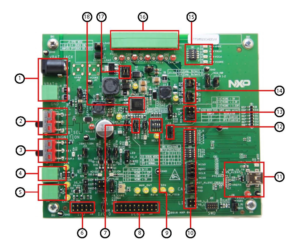
| Number | Description |
|---|---|
| 1 | VBAT connectors — use either jack connector or Phoenix connector to supply board |
| 2 | VBAT switch — select VBAT from jack or from Phoenix connector |
| 3 | Ignition key — ignition key from car |
| 4 | LIN bus — LIN bus connector |
| 5 | CAN bus — CAN bus connector |
| 6 | I/Os — input and output from FS45XX/FS65XX (IO0, IO2, IO3, IO4, IO5, GND, VKAM, VDDIO, VBAT) |
| 7 | DBG mode select |
| 8 | Debug connector — could be used for debug purpose (CAN TX/RX, LIN TX/RX, SPI, Debug, FS0B, FS1B, INTB) |
| 9 | VCCA and VAUX selection — select 3.3 V/5.5 V configuration for VCCA and VAUX |
| 10 | MCU to FS65/FS45 connection — connects part or totality of signals between the KL25Z MCU and FS65XX/FS45XX |
| 11 | KL25 MCU — location of MCU and USB connector for control through FlexGUI |
| 12 | DFS mode select — enables or disables the deep fail-safe function |
| 13 | VCORE selection — selects either 1.23, 3.3, or 5.0 V on VCORE DC-DC |
| 14 | Compensation network — selects either Network 1 or 2 |
| 15 | Power supplies LED — visualizes regulator state (On or Off). The switches can disconnect LEDs |
| 16 | Power supplies — connector for power supplies (CAN_5V/VPRE/VCORE/VCCA/VAUX) |
| 17 | Buck/buck or boost selection — these jumpers select VPRE mode as a buck or buck or boost |
| 18 | FS45xx/FS65xx |
3. Install Software
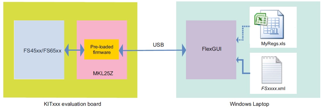
The kit is bundled with software allowing the user to interact directly with the onboard MCU during the development process. The boards contain an MKL25Z Kinetis processor pre-loaded with firmware controlling communication with the FS45xx/FS65xx MCU. A graphical user interface installed on a PC serves as the user interface to the evaluation board. When connecting the evaluation board to a PC through a USB cable, the following data exchanges are available:
- SPI access (read and write) to FS45xx/FS65xx
-
ADC readout, connected to regulators
- VPRE
- VCORE
- VAUX
- VCCA
- CAN_5V
- MUX_OUT
- VDDIO
- VKAM
- I/O readout, connected to IO_0 to IO_5
- FS0B/FS1B readout
- RSTB readout
- CAN generated TX signal
- LIN generated TX signal with loopback checking
Note that MCU connections to FS45xx/FS65xx can be fully isolated by removing related jumpers and switching off the related switch.
The software bundle also includes an XML file containing register descriptions for the FS45xx or FS65xx (depending on the evaluation board). This file must be installed for the GUI to work properly. In addition, an optional Excel file can be created to facilitate setting several registers at a click.
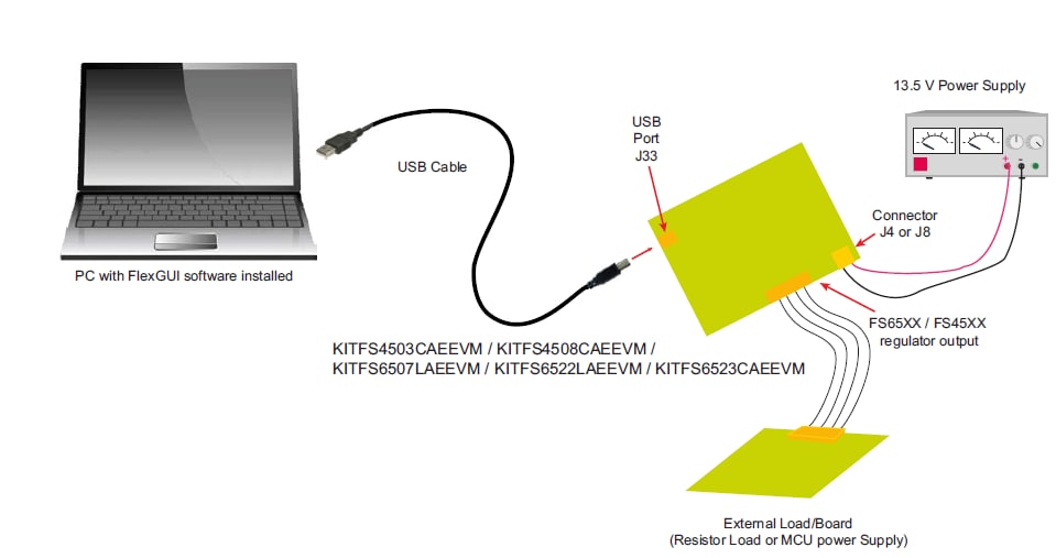
4. Configure the Hardware
The evaluation board must be connected to a PC through the USB port on the board. A 13.5 V power supply connects either to a jack connector (J4) or a Phoenix connector (J8). The evaluation board connects to an external load or another board through connector JP1.
To configure the hardware and workstation, complete the following procedure:
- With the power switched off, attach the DC power supply to either the Jack connector (
J4) or the Phoenix connector (J8) on the evaluation board. There is no difference between the two connectors other than plug compatibility. - Attach a load or an external board through connector
JP1. - Connect a USB cable from the evaluation board USB port (
J33) to the USB port on a PC with the FlexGUI installed. - Turn on the DC power supply.
Design Resources
Board Resources
Software
Get Help
Forums
Connect with other engineers and get expert advice on designing with the FS45xx and FS65xx on one of our community sites.