Smart IoT Sensing Development Tools
Contents of this document
-
Plug It In
-
Get Software
-
Build, Run
-
Create
Sign in to save your progress. Don't have an account? Create one.
Purchase your IoT Sensing Software Development Kit
1. Plug It In
1.1 Select a Sensor Demonstration Kit
Go to Sensor Evaluation Boards and select the desired Demonstration Kit.
- Take FRDM-K22F-A8974 Demonstration Kit as an example
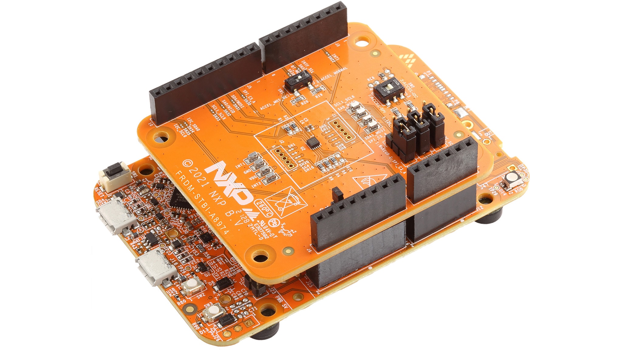
1.2 Plug It In
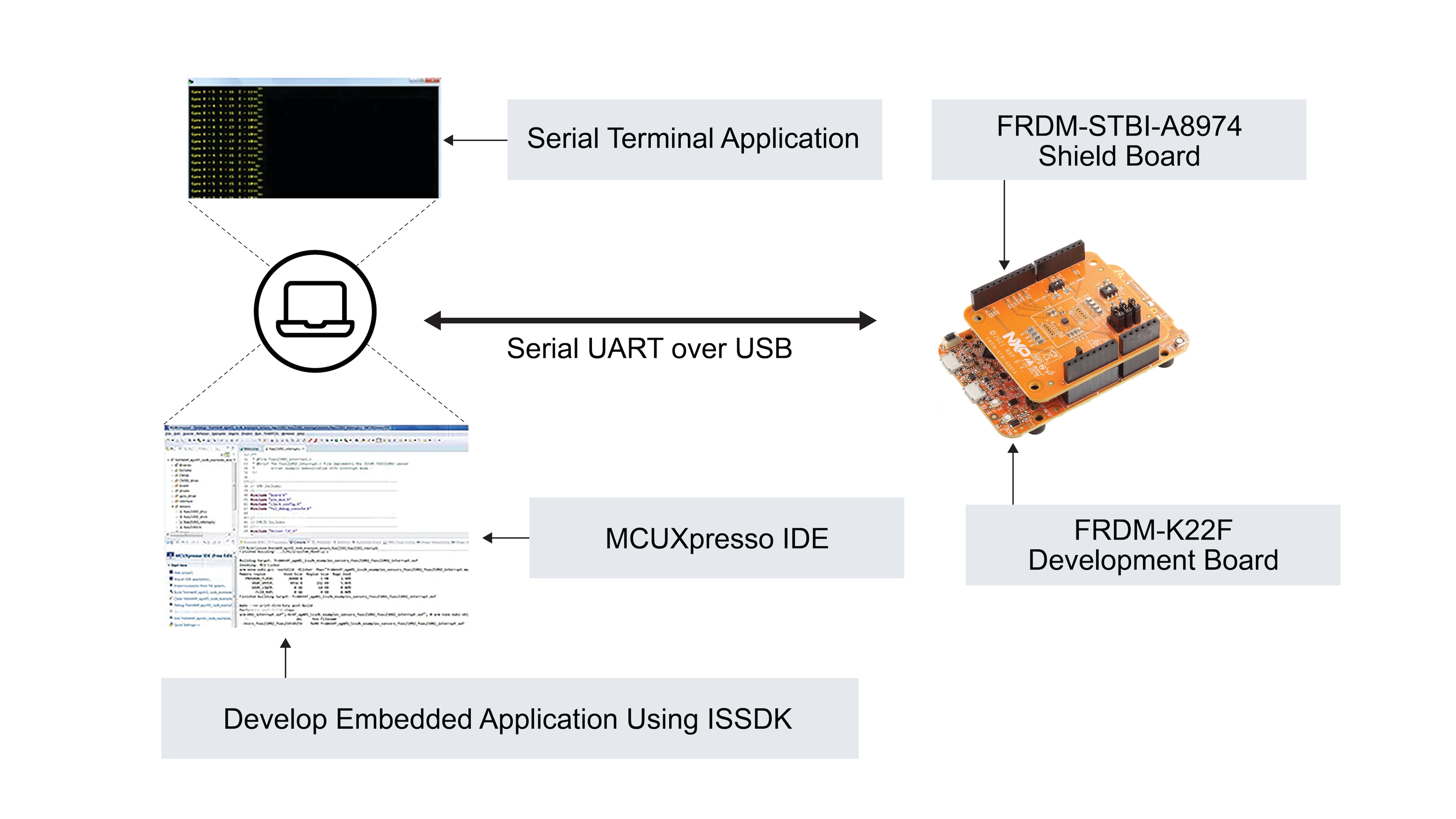
Connect the Sensor Demonstration Kit to the PC via the USB cable between the OpenSDA USB port on the board and the USB connector on the PC.
1.3 OpenSDA
Kinetis Freedom MCU boards are supplied with OpenSDA firmware pre-loaded. For a smooth 'Out of Box Sensor Demonstration' with STB-CE, make sure that the latest version of the default OpenSDA bootloader and firmware application is on the Freedom development board. This allows debugging, flash programming and serial communication over a USB cable.
The default OpenSDA firmware for all Freedom based sensor demonstration kits used with STB-CE are as follows:
- DAPLink: FRDM-K22F, FRDM-K64F, FRDM-KW41Z, FRDM-KE15Z, RD-KL25-AGMP01
- PEMicro: FRDM-KL25Z, FRDM-KL27Z
Obtain the latest OpenSDA drivers for FRDM boards from the link below.
Locate the section "Download – OpenSDA Bootloader and Application" and select your FRDM Board from the dropdown list. Strictly follow the provided instructions to program the board.
Note: For Windows 10 systems, the older versions of the OpenSDA drivers could get corrupted when the board is plugged on a Windows 10 machine. As a result, many boards might get not detected as an MSD or a COM port on Win 10. The latest versions of the OpenSDA software are compatible with Windows 10 and can be obtained from the link above. The current FRDM-K64F, FRDM-K22F, FRDM-KL25Z and RD-KL25-AGMP01 boards come with an older version of OpenSDA drivers from the factory and require a mandatory OpenSDA update.
1.4 PC Configuration
The output data from the provided example applications is provided over the MCU UART. This requires that the driver for the board’s virtual COM port is installed on the PC. The board MUST be plugged into the PC before the driver installer is run.
If you have not installed already an ARM IDE toolchain, download and install the Windows drivers corresponding to the default OpenSDA Application selected above:
Once the Windows Serial Port Drivers are installed on the PC, determine the port number of the board’s virtual COM port by opening the device manager and looking under the "Ports" group.
The demonstration kit is now ready to communicate with the PC.
2. Get Software
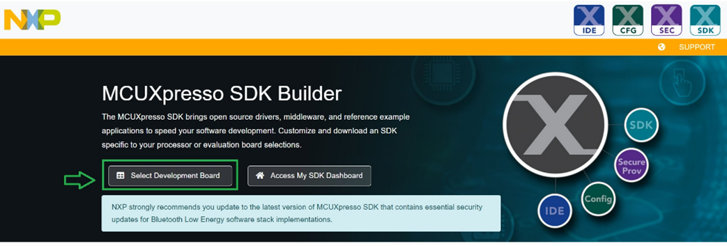
2.1 Go to MCUXpresso Configuration Tools
Available in both online and desktop editions, MCUXpresso SDK Builder creates a custom SDK for Kinetis, LPC and i.MXRT microcontrollers.
- Click on Select Development Board
2.2 Build FRDM-K22F-A8974 Kit Configuration
- Select the Sensor Demonstration Kit as shown below. For this example, the FRDM-K22F-A8974 Demonstration Kit is selected
- Choose the Operating System for the desired host, the IDE toolchain and any other Optional Middleware. For this example, as depicted, Windows, MCUXpresso IDE and ISSDK middleware is selected
- Now, click on Download SDK
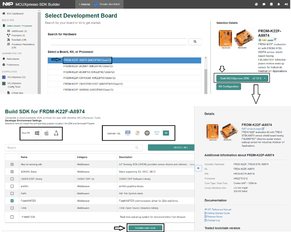
This builds the SDK package for the demonstration kit. A request is sent to the build server. Requests for SDK packages are served in the order they are received. Notification is provided when the package is ready. The package is provided as a zip file. When notified, download the package (zip file) to the local PC
2.3 Install the Toolchain
NXP offers a complimentary toolchain called MCUXpresso IDE.

Want to use a different toolchain?
No problem. The MCUXpresso SDK includes support for other tools such as: IAR , Keil , command-line GCC .

2.4 Install Visualization
The sensor output of ISSDK example applications can be directly visualized on terminal applications like RealTerm , Tera Term , or PuTTY .
ISSDK also enables sensor visualization and data analysis on the FreeMASTER Sensor Tool.
3. Build, Run
Explore the SDK Package.
3.1 Unzip the Downloaded Package
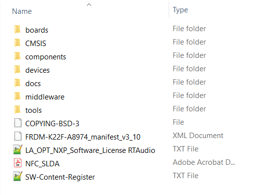
3.2 Find the ISSDK Example Sensor Applications
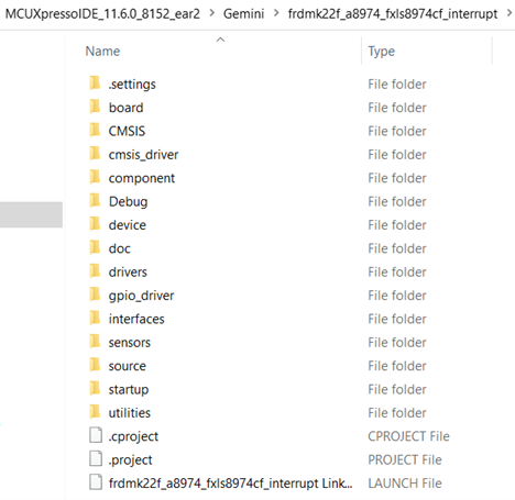
The CMSIS, devices, docs, rtos and tools directories are unchanged from the standard MCUXpresso SDK deployments. The ISSDK folder appears as frdmk22f_a8974 in the "/boards" directory.
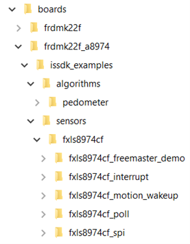
As shown above, ISSDK provides out-of-box example projects for the FXLS8974CF sensor. In addition, ISSDK includes algorithms such as Pedometer. These sensor out-of-box example projects are ready to build and run with the FRDM-K22F-A8974 Demonstration Kit.
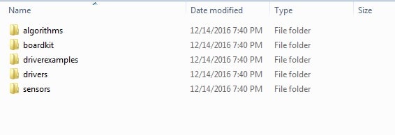
In addition, a new middleware folder for ISSDK is created containing the ISSDK drivers, algorithms and other support files as follows:
3.3 Build and Run ISSDK Examples
If one or more of the demo applications sounds interesting, you're probably wanting to know how you can build and run yourself. Let us take "fxls8974cf_interrupt" out-of-box example available as part of the downloaded SDK package and try running it with our chosen IDE: MCUXpresso.
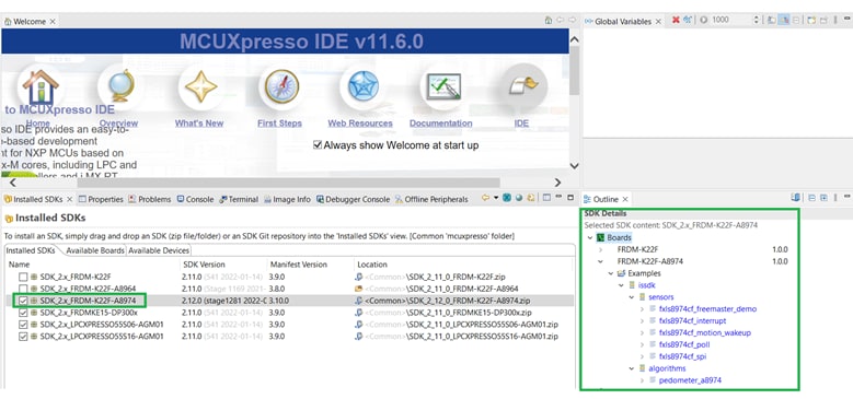
3.4 Install the Downloaded FRDM-K22F-A8974 SDK Package
- Install the downloaded FRDM-K22F-A8974 SDK Package into MCUXpresso IDE (Simply drag and drop the Zipped SDK Package as it is to the "Installed SDKs" View)
- Once the SDK installation is completed, click on "Import SDK examples"
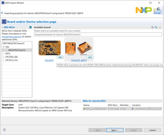
3.5 SDK Import Wizard
- In the SDK import Wizard, choose FRDM-K22F-A8974 Demo Kit as the available board for your project
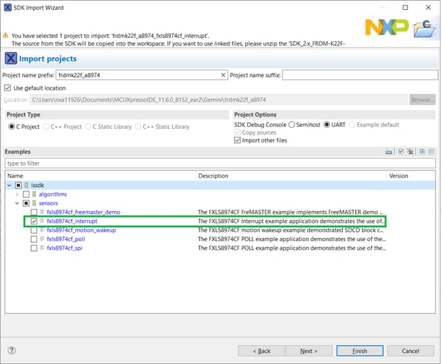
3.6 Import ISSDK
- Import any existing ISSDK example from the list of available projects. We have chosen the "fxls8974cf_interrupt" example:
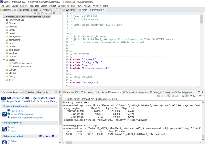
3.7 Build/Run
- Build and run the imported project, loading the firmware to your FRDM-K22F-A8974 Kit
- The MCU board is now programmed and is ready to output FXLS8974CF sensor data
For the firmware to be loaded successfully, review Steps 1.3 and 1.4 to be sure that the MCU board has the latest OpenSDA FW and the PC has the appropriate Windows Serial Drivers
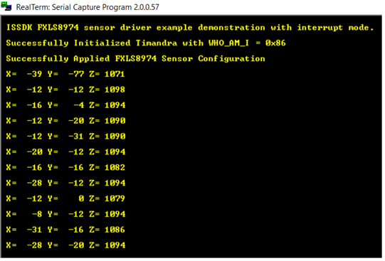
3.8 View the Output
Terminal applications, such as Realterm, TeraTerm, or PuTTY, can be used to view the sensor output from the board. Refer to the readme.txt file in your workspace (standalone project) to configure the serial terminal correctly for successful communication with the Demonstration Kit. When the demonstration runs successfully, gyroscope output samples can be seen on the terminal window.
4. Create
4.1 MCUXpresso IDE
The MCUXpresso IDE creates a standalone project folder for the chosen project under your workspace folder:
4.2 Success
Now, start your embedded application development, open the project from the folder with the desired IDE and start developing a custom application.
Design Resources
Support
Forums
Connect with other engineers and get expert advice on designing with the IOT-SENSING-SDK on our community site.
On this page
- 2.1
Go to MCUXpresso Configuration Tools
- 2.2
Build FRDM-K22F-A8974 Kit Configuration
- 2.3
Install the Toolchain
- 2.4
Install Visualization