Getting Started With the LPCXpresso860-MAX Evaluation Board
Contents of this document
-
Plug It In
-
Get Software
-
Build, Run
-
Configure Software
Sign in to save your progress. Don't have an account? Create one.
1. Plug It In
Let's take your LPCXpresso860-MAX for a test drive. You have the choice of watching the sequence in a short video or following the detailed actions listed below.
1.1 Get Familiar With the Board
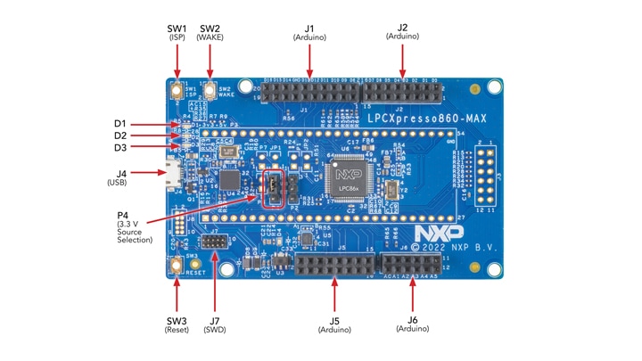
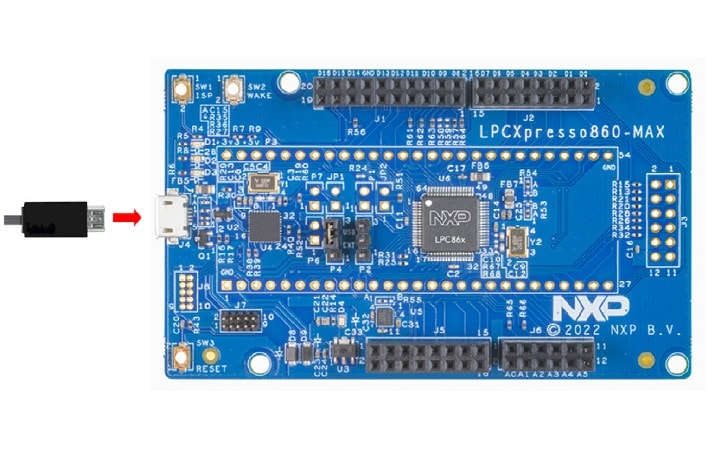
1.2 Attach the USB Cable
Plug the USB cable into the only one USB connector(J4), as is shown in the photo below
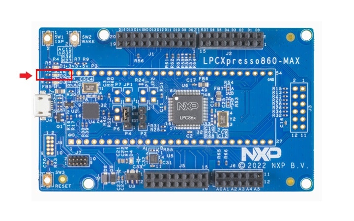
1.3 Run the Out of the Box Demo
Your LPCXpresso860-MAX comes loaded with a "LED blinky" demo, explained below and a demo that exercises the Cortex-M0+, described in the next section.
When the board is powered, the LED D2 should flash on and off.
2. Get Software
2.1 Jump Start Your Design With the MCUXpresso SDK
The MCUXpresso Software Development Kit (SDK) is complimentary and includes full source code under a permissive open source license for all hardware abstraction and peripheral driver software.
Click below to download the latest SDK release for the LPCXpresso860-MAX, make sure you select Host OS, Toolchain and desired components.

You can also use the online SDK Builder to create a custom SDK package for the LPCXpresso860-MAX.
2.2 Get Your Toolchain
MCUXpresso IDE is development platform ecosystem from NXP. It provides an end-to-end solution enabling engineers to develop embedded applications from initial evaluation to final production.

Want to use a different toolchain? Need help with choosing?
The MCUXpresso SDK includes support for other tools such as IAR, Keil and command-line GCC.

2.3 MCUXpresso Config Tools
The MCUXpresso Config Tool is an integrated suite of configuration tools that guides users in creating new MCUXpresso SDK projects and also provides pin and clock tools to generate initialization C code for custom board support. It is fully integrated into MCUXpresso or you can download a separate tool.

To learn more about the basic interactions between the tools while working with either an imported MCUXpresso SDK example project or creating a new project within the IDE, watch this three-part video series.
Basic Application Development Using MCUXpresso IDE and MCUXpresso Config Tools
2.4 Install Drivers and Update Debug Probe Firmware
Before using your board, it is recommended that you download update the firmware for the LPC11U35 debug probe on the board. Start by downloading the firmware and driver package and from here.
If using Windows 7 or 8, run the device driver installation executable file that is included in this package.
Pressed RESET button(SW3) then plug in the board:
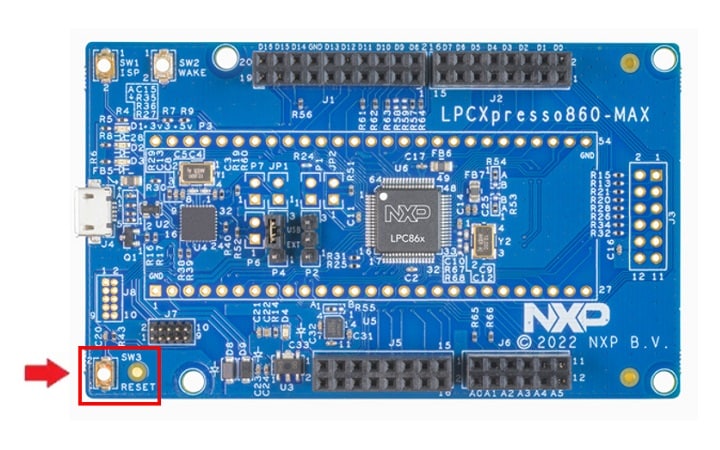
You will see a device called CRPDISABLED appear in your computer file manager. Go to this drive and delete the file “firmware.bin” from that drive. Drag and drop the firmware.bin file from the firmware and driver package you just downloaded onto the CRPDISABLED drive. Released RESET button(SW3) then disconnect and reconnect the USB cable, then wait a few seconds for the new device driver to install.
You will notice that once you power the board, blue user LED at the top left of the board will flash. This is a basic program that comes pre-programmed on the LPC865 device to show it is working.
2.5 Serial Terminal
Many of the MCUXpresso SDK examples applications output data over the MCU UART. Install and configure your preferred terminal software to 9600 baud rate, 8 data bits, no parity and 1 stop bit. To determine the port number of the LPCXpresso860-MAX 's virtual COM port, open the device manager and look under the "Ports" group.
Not sure how to use a terminal application? Try one of these tutorials: MCUXpresso Terminal Tutorial, Tera Term Tutorial, PuTTY Tutorial
3. Build, Run
3.1 Explore the MCUXpresso SDK Example Code
The MCUXpresso SDK comes with a long list of example applications code. To see what's available, browse to the SDK boards folder of your SDK installation and select LPCXpresso860-MAX.
<SDKInstallDirectory>/boards/lpcxpresso860maxTo learn more about specific example code, open the readme.txt file in an example's directory.
3.2 Build, Run and Debug MCUXpresso SDK Examples
If one or more of the demo applications or driver examples sounds interesting, you're probably wanting to know how you can build and debug yourself. The Getting Started with MCUXpresso SDK guide provides easy, step-by-step instructions on how to configure, build and debug demos for all toolchains supported by the SDK.
Use the guide below to learn how to open, build and debug an example application using the MCUXpresso IDE.
Running a demo using MCUXpresso IDE
Import the MCUXpresso SDK
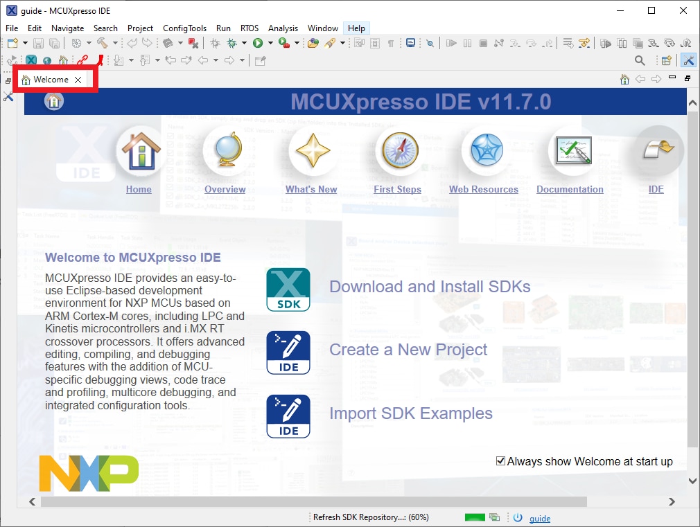
- Open the MCUXpresso IDE and close the welcome page
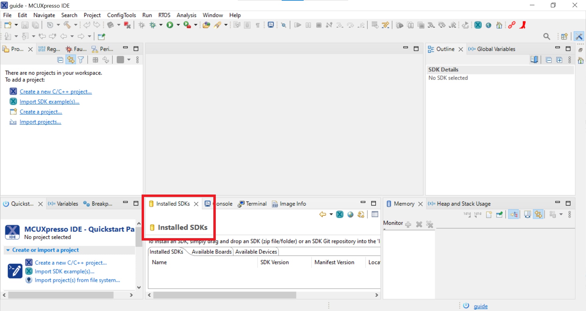
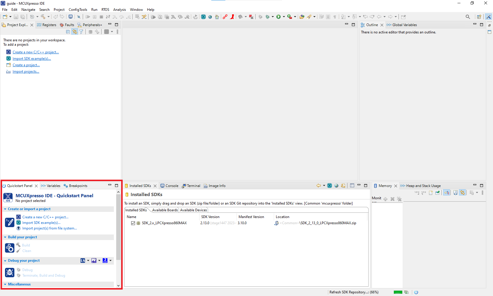
- Switch to the Installed SDKs view within the MCUXpresso IDE window
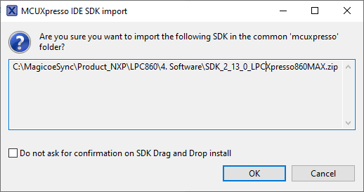
- Drag and drop the LPCXpresso860MAX SDK(zipped) file into the Installed SDKs view
- You will get the following pop-up. Click on OK to continue the import:
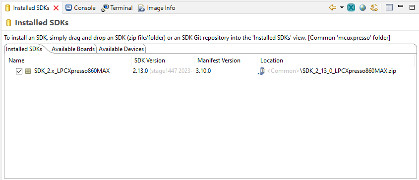
- The installed SDK will appear in the Installed SDKs view as shown below:
Build an Example Application
The following steps will guide you through opening the hello_world example.
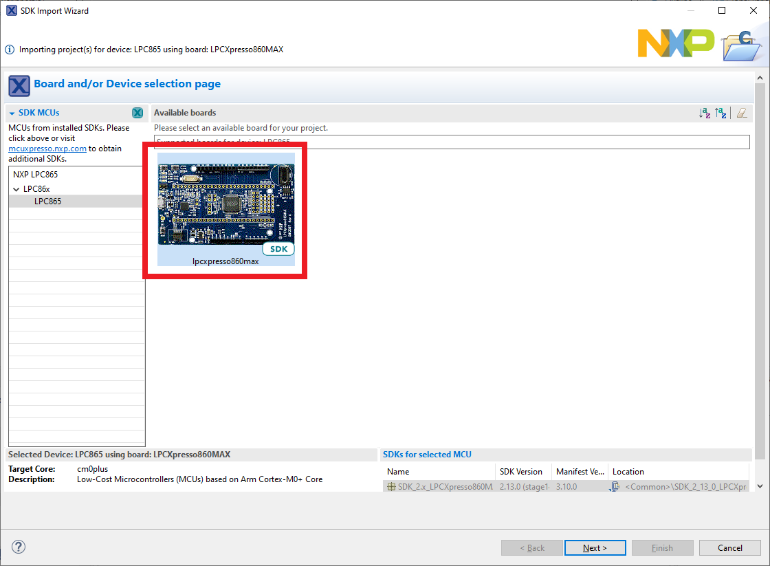
- Find the Quickstart Panel in the lower left-hand corner
- Then click on import SDK example(s)...

- Click on the LPCXpresso860MAX board to select that you want to import an example that can run on that board, and then click on Next
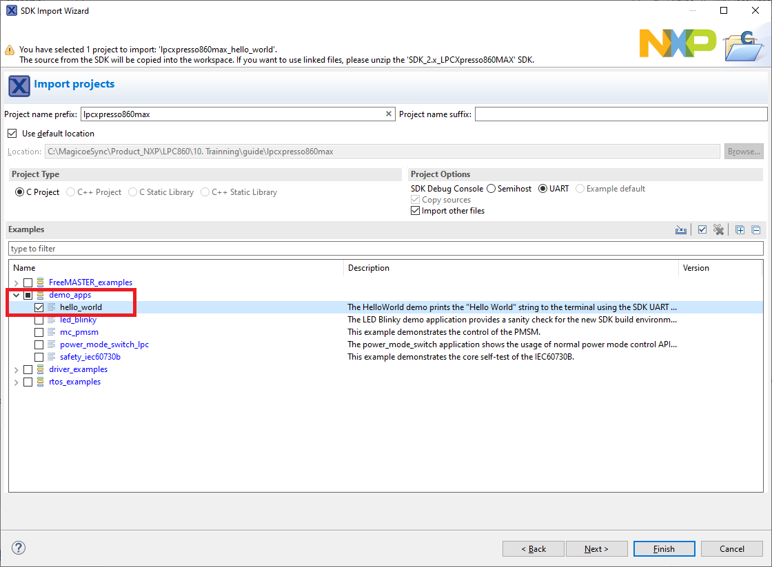
- Use the arrow button to expand the demo_apps category, and then click the checkbox next to hello_world to select that project. To use the UART for printing(instead of the default semihosting), Select UART as the SDK Debug Console checkbox under the project options. Then, click on Finish
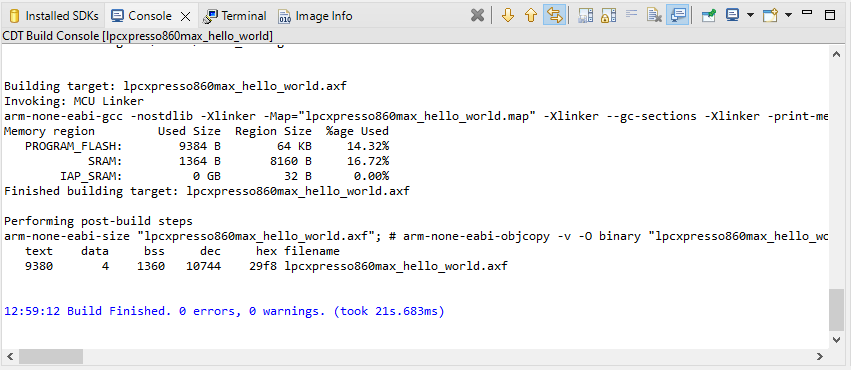
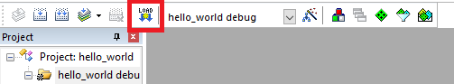
- Now build the project by clicking on the project name and then in the Quickstart Panel click on Build or press "Ctrl + b"
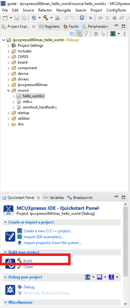
- You can see the status of the build in the Console tab
Run an Example Application
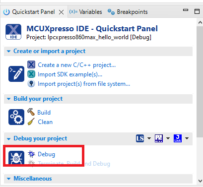
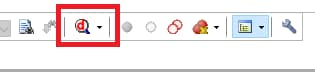
- Now that the project has been compiled, you can now flash it to the board and run it
- Make sure the LPCXpresso860MAX board is plugged in and click on Debug in the Quickstart Panel
- MCUXpresso IDE will probe for connected boards and should find the CMSIS-DAP debug probe that is part of the integrated DAPLink circuit on the LPCXpresso860MAX. Click on OK to continue
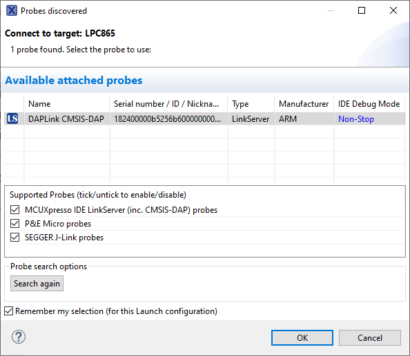
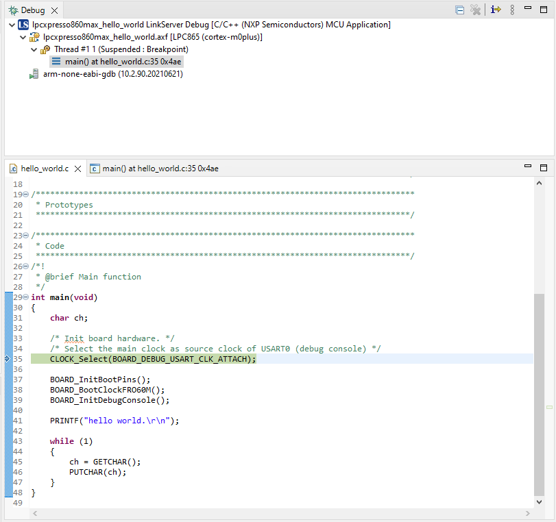
- The firmware will be downloaded to the board, and the debugger started
-
Open a terminal program and connect to the COM port the board enumerated as. Configure the terminal with these settings
- 9600 baud rate
- No parity
- 8 data bits
- 1 stop bit
- Start the application by clicking the "Resume" button
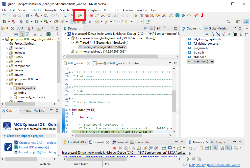
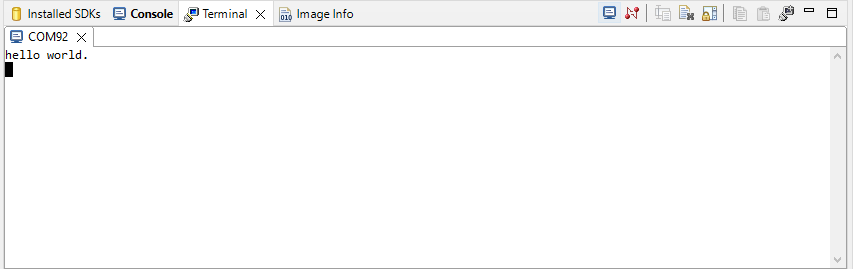
- The hello_world application is now running, and a banner is displayed on the terminal. If this is not the case, check you terminal settings and connections
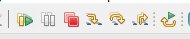
- Use the controls in the menu bar to pause, step into, and step over instructions, and then stop the debugging session by click on the Terminate icon:
Using a different toolchain? This demo is also available for IAR and KEIL.
Running a demo using IAR Embedded Workbench IDE
Build an Example Application
The following steps will guide you through opening the hello_world application. These steps may change slightly for other example applications as some of these applications may have additional layers of folders in their path.
- First unzip the previously downloaded SDK
-
If not already done, open the desired example application workspace. Most example application workspace files can be located using the following path:
<install_dir>/boards/<sdk_board_name>/<example_type>/<application_name>/iarUsing the hello_world demo as an example, the path is:
<install_dir>/boards/lpcxpresso860max/demo_apps/hello_world/iar - Select the desired build target from the drop-down. For this example, select the “hello_world - Debug” target
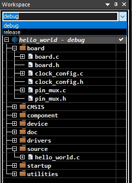
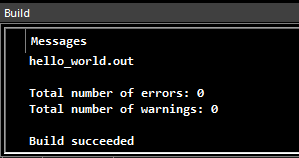
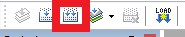
- To build the application, click the “Make” button, highlighted in red below

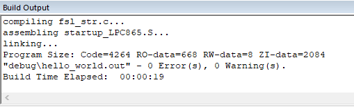
- The build will complete without errors
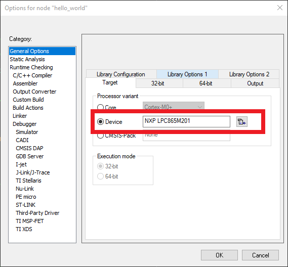
Note
In case of building errors, make sure that the correct Board is selected, right click in the project >> Options >> General Options >> Target >> Device, Select the NXP LPC865M201, this board is supported in IAR Embedded Workbench for Arm version 9.30.1 or Higher.
Run an Example Application
The LPCXpresso860-MAX EVK board comes loaded with the CMSIS-DAP debug interface from the factory.
- Connect the development platform to your PC via USB cable to
J4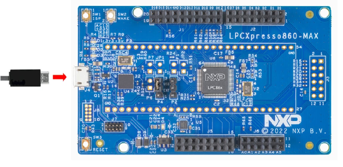
-
Open the terminal application on the PC (such as PuTTY or Tera Term) and connect to the debug COM port you determined earlier. Configure the terminal with these settings:
- 9600 baud rate
- No parity
- 8 data bits
- 1 stop bit
- Click the "Download and Debug" button to download the application to the target

- The application is then downloaded to the target and automatically runs to the main () function
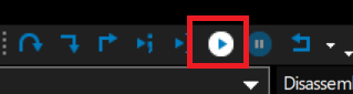
- Run the code by clicking the "Go" button to start the application
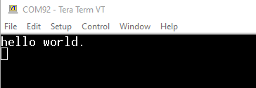
- The hello_world application is now running, and a banner is displayed on the terminal. If this is not the case, check your terminal settings and connections
Running a demo using Keil® MDK/µVision®
- Install CMSIS device pack
-
After the MDK tools are installed, Cortex® Microcontroller Software Interface Standard (CMSIS) device packs must be installed to fully support the device from a debug perspective. These packs include things such as memory map information, register definitions and flash programming algorithms. Follow these steps to install the appropriate CMSIS pack
- Open the MDK IDE, which is called µVision. In the IDE, select the "Pack Installer" icon

- In the Pack Installer window, search for “LPC86” to bring up the LPC86x family. Click on the LPC865 name, and then in the right-hand side you'll see the NXP::LPC865DFP pack. Click on the “Install” button next to the pack. This process requires an internet connection to successfully complete. - After the installation finishes, close the Pack Installer window and return to the µVision IDE
- Open the MDK IDE, which is called µVision. In the IDE, select the "Pack Installer" icon
Build the Example Application
The following steps will guide you through opening the hello_world application. These steps may change slightly for other example applications as some of these applications may have additional layers of folders in their path.
-
If not already done, open the desired demo application workspace in:
<install_dir>/boards/<sdk_board_name>/<example_type>/<application_name>/mdkThe workspace file is named <application_name>.uvmpw, so for this specific example, the actual path is:
<install_dir>/boards/LPCXpresso55S06/demo_apps/hello_world/mdk/hello_world.uvmpw - To build the demo project, select the "Rebuild" button, highlighted in red
- The build will complete without errors
Run an Example Application
The LPCXpresso860-MAX EVK board comes loaded with the CMSIS-DAP debug interface from the factory
- Connect the development platform to your PC via USB cable to
J4 -
Open the terminal application on the PC (such as PuTTY or Tera Term) and connect to the debug COM port you determined earlier. Configure the terminal with these settings:
- 9600 baud rate
- No parity
- 8 data bits
- 1 stop bit
- After the application is properly built, click the "Download" button to download the application to the target
- Click on “Start/Stop Debug Session” to open the debug view
- Run the code by clicking the "Run" button to start the application

- The hello_world application is now running, and a banner is displayed on the terminal. If this is not the case, check your terminal settings and connec
3.3 Building and Debugging MCUXpresso SDK Examples
Now it's time to plug in the board to debug your project...
- Make sure that the jumper
P4is shorted with 2-3 - Plug the micro USB cable from the PC into the Debug Link micro USB connector as shown
- In the Project Explorer window in MCUXpresso select your project
- In the Quick Start Panel click on Debug
- Choose the CMSIS-DAP debug interface
- Hit Resume to get the code running after the breakpoint at the beginning of main ()
More details can be found in the SDK getting started documents found in the SDK folder.
<SDKInstallDirectory>/docs/Getting Started with MCUXpresso SDK.pdf3.4 More Examples
Several examples, demos and drivers are available within the SDK to help you get started. Some common examples are listed below:
- PMSM motor control
- Power manager demo
- IEC60730 safety
4. Configure Software
4.1 Clone an Example Project From MCUXpresso SDK
Option A: Use the MCUXpresso IDE to clone an example project.
Use MCUXpresso IDE
Build an Example Application
The following steps will guide you through opening the FlexTimer PWM duty cycle change example. The example sets up a PWM signal and periodically updates the signals duty cycle.
- Find the Quickstart Panel in the lower left-hand corner
- Then click on Import MCUXpresso SDK Examples.(s)…
- Click on the LPCXpresso860-MAX board to select that you want to import an example that can run on that board, and then click on Next
- Use the arrow button to expand the driver examples category, then expand the FTM(FlexTimer) examples, click on the checkbox next to
ftm_simple_pwmto select it. To use the UART for printing (instead of the default semihosting), Select UART as the SDK Debug Console checkbox under the project options. Then, click on Finish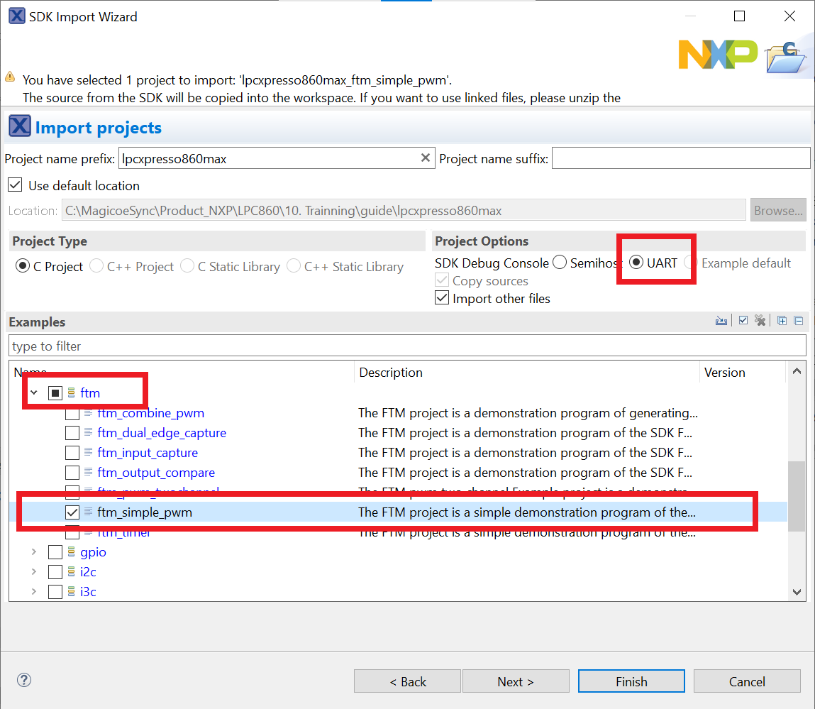
- Click on the “
lpcxpresso860max_ftm_simple_pwm” project in the Project Explorer View and build, compile and run the demo as described previously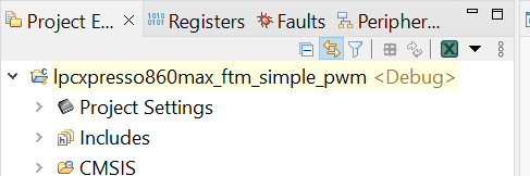
-
You could see the change of the duty cycle using an oscilloscope through port
J1_7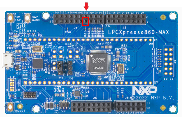
- Terminate the debug session
Option B: Use the MCUXpresso Config Tool to clone an existing MCUXpresso SDK example for use with third-party IDEs.
Use MCUXpresso Config Tools
The following steps will guide you through opening the FlexTimer PWM duty cycle change(ftmsimplepwm) example. The example sets up a PWM signal and periodically updates the signals duty cycle.
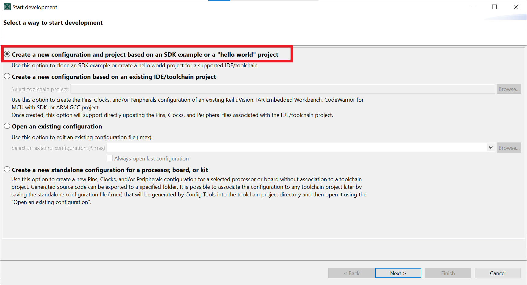
- Open the MCUXpresso Config Tool
- In the wizard that comes up, select the “Create a new configuration based on an SDK example or hello word project” radio button and click on Next
- On the next screen, select the location of the MCUXpresso SDK that you had unzipped earlier. Then select the IDE that is being used. Note that only IDEs that were selected in the online SDK builder when the SDK was built will be available and click on clone select example
- Then select the project to clone. For this example, we want to use the SCTimer PWM project. You can filter for this by typing “ftm” in the filter box and then selecting the “sctimerpwmwithdutycyclechange” example project. You can then also specify where to clone the project and the name. Then click on Finish
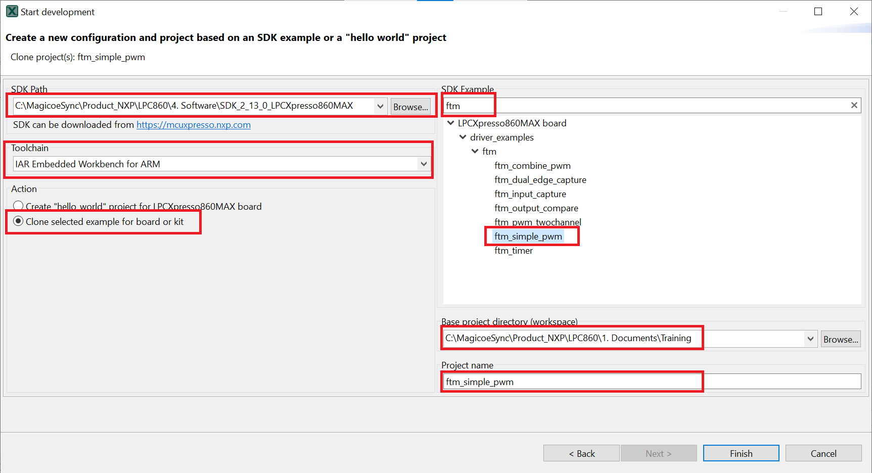
- After cloning go to the directory you selected and open the project for your IDE. Import, compile and run the project as done in previous sections
-
You could see the change of the duty cycle using an oscilloscope through port
J1_7
- Terminate the debug session
4.2 Use the Pin Tool
Now, let's use the Pins tool that is part of the MCUXpresso Config Tool to show how to add a new GPIO pin to your project to blink an LED.
Use MCUXpresso IDE Pins Tools
To open pin tools in MCUXpresso IDE
-
Open the pins tool by right-clicking on the “
lpcxpresso860max_ftm_simple_pwm” project, and selecting “MCUXpresso Config Tools” and then “Open Pins”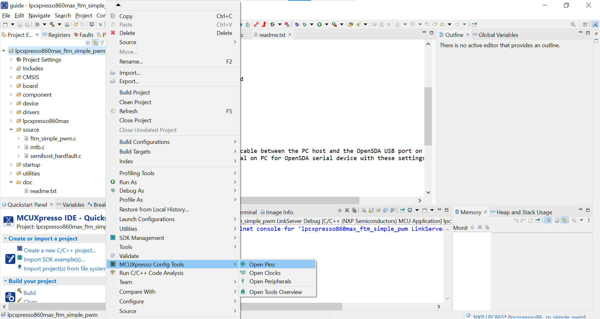
The pins tool should now display the pin configuration for the PWM project.
To open pin tools in MCUXpresso Config tools
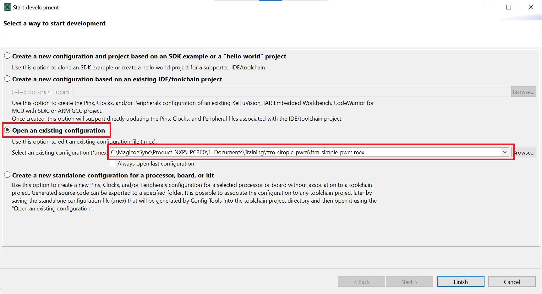
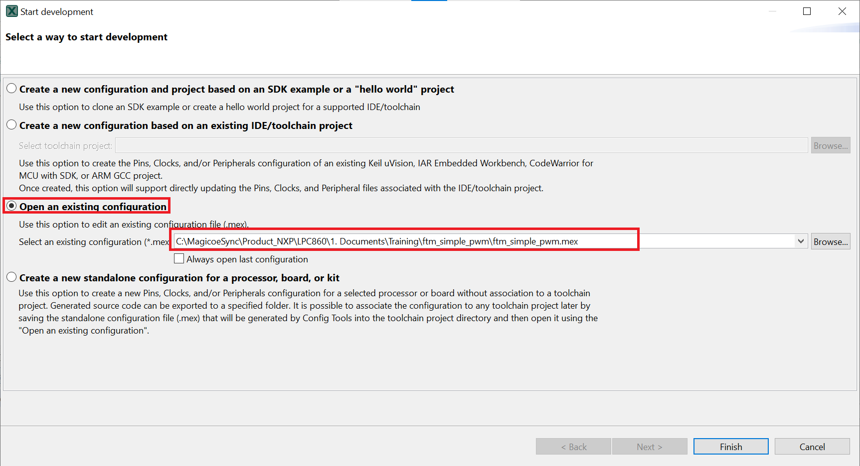
- Open the MCUXpresso Config Tool
- In the wizard that comes up, select the “Open existing configuration” radio button, then select the project that you had clone and click on Next
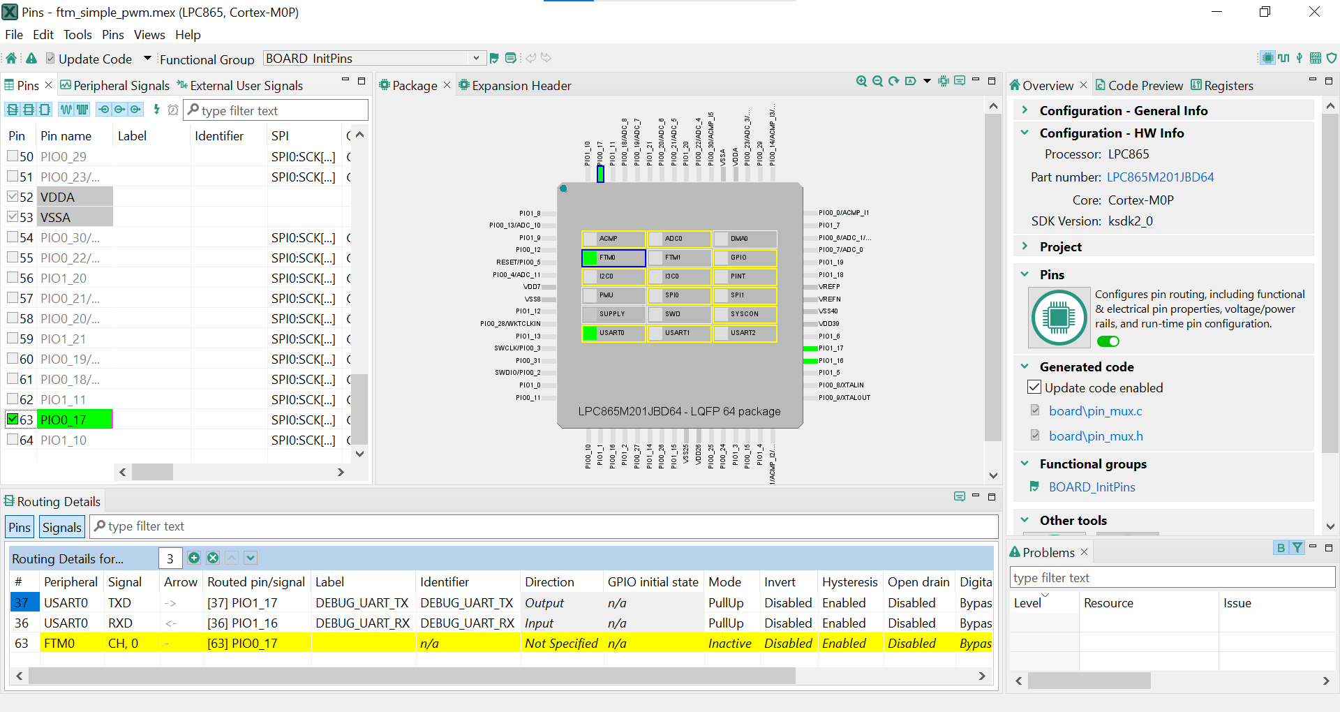
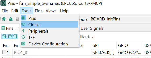
- Open the pins tool by selecting Tools->Pins from the toolbar
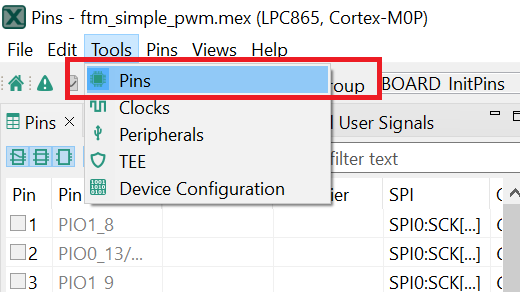
- The pins tool should now display the pin configuration for the FlexTimer PWM project
Use the pins tools to modify the GPIO routed pin
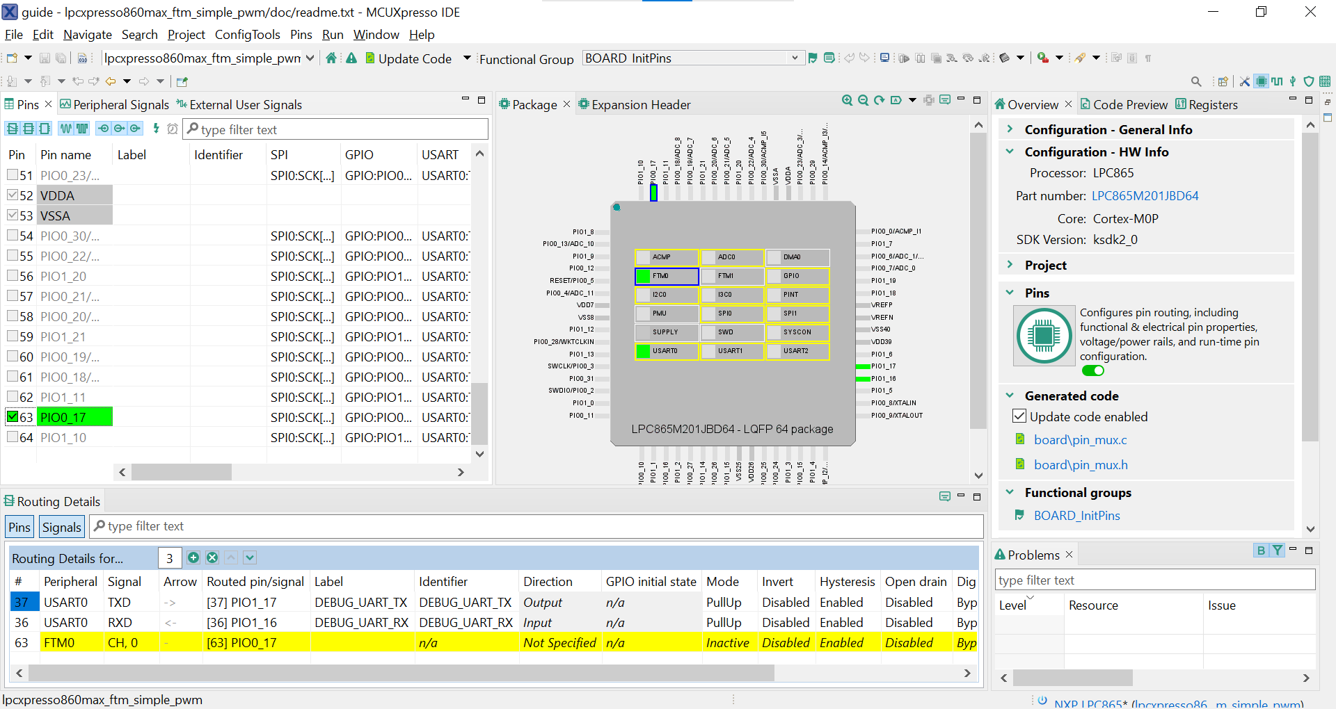
- We'll use MCUXpresso IDE for the rest of the instructions, but the same steps can be done in MCUXpresso Config tools for third-party IDEs. In the Pins view deselect the “Show not routed pins” checkbox to see only the routed pins, you also going to see the pins that are routed by default. Routed pins have a check in a green box next to the pin name. The functions selected for each routed pin are highlighted in green
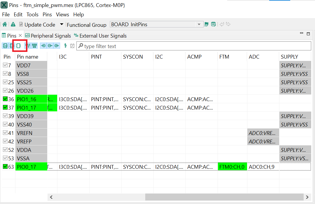
- In the current configuration,
PIO0_17is routed as aFTM0Channel0. Let's disable,PIO0_17, and change the mux setting ofPIO1_1to use its FlexTimer functionality to output PWM waveform. - Disable,
PIO0_17as an FlexTimer by clicking the “FTM0:CH,0” field under the FTM column. The pin will then be disabled (pin will no longer have check in box) and therefore disappear from the list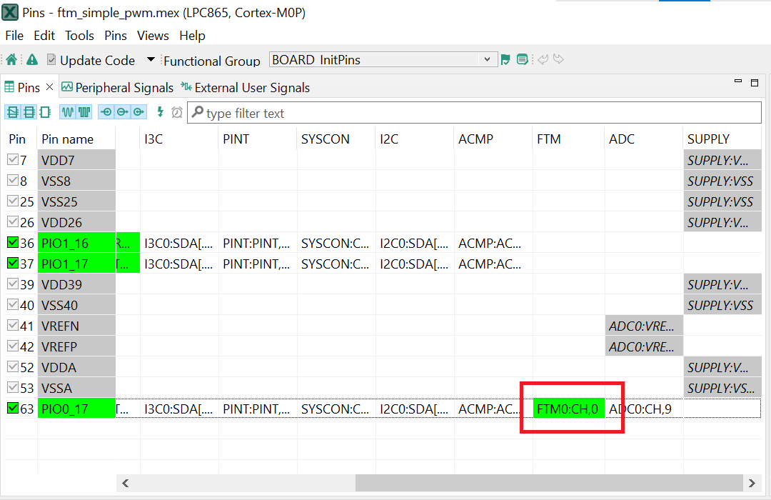
- Now, route
PIO1_1as anFTM0Chanel 0. First, select the “Show not routed pins” so that all the pins are displayed again. Then, searchPIO1_1in the pins view. Finally, click the box under the FTM column “FTM0:CH,0”. The box will highlight in green, and a check will appear next to the pin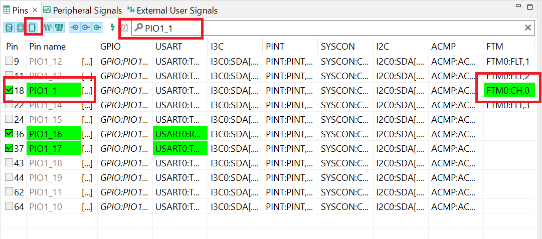
- Now it's time to implement these changes into the project by exporting the new updated
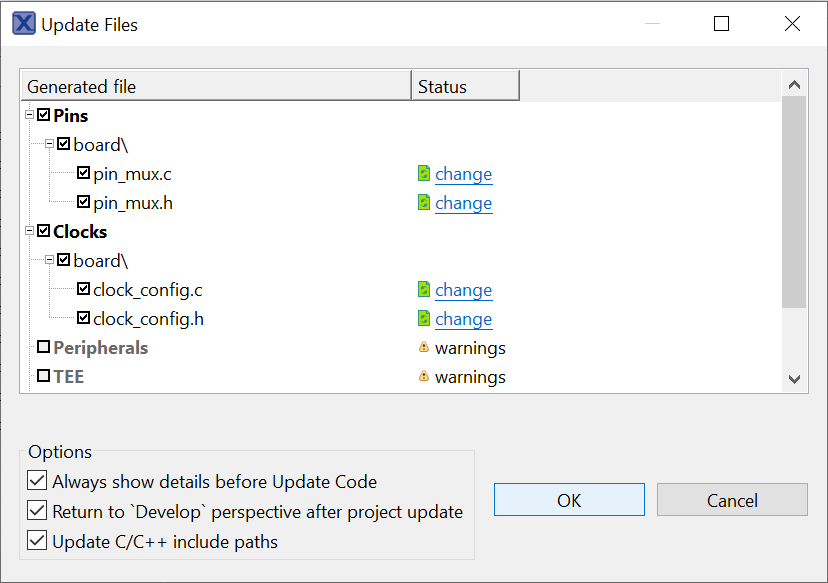
pinmux.candpinmux.hfiles that are generated by the Pins tool. Click on Update Project in the menu bar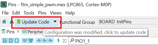
- The screen that pops up will show the files that are changing and you can click on “diff” to see the difference between the current file and the new file generated by the Pins tool. Click on “OK” to overwrite the new files into your project
- Now inside the IDE, open the
pinmux.cfile, you will foundFTM0:CH,0set to "kSWMFTM_Selection1"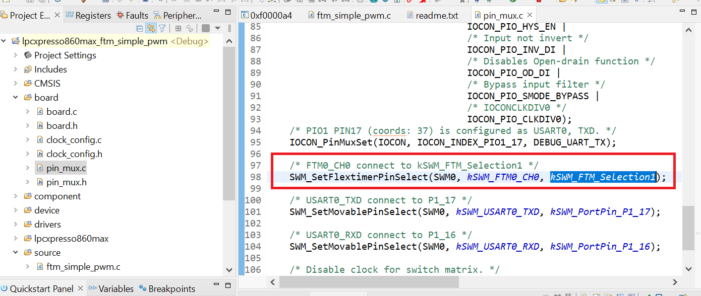
- Build and download the project as done in the previous section
-
Run the application. You could see the change of the duty cycle using an oscilloscope through port
J5_5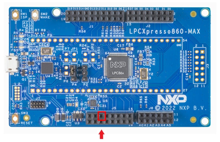
- Terminate the debug session
4.3 Use the Clocks Tool
Next use the Clocks tool that is part of the MCUXpresso Config Tool to change the clock settings and change the rate that the LED blinks.
Use MCUXpresso Clock Config Tools
To Open Clock Tools in MCUXpresso IDE
- Open the Clock tool by right-clicking on the “
lpcxpresso860maxftmsimple_pwm” project and selecting “MCUXpresso Config Tools” and then “Open Clocks”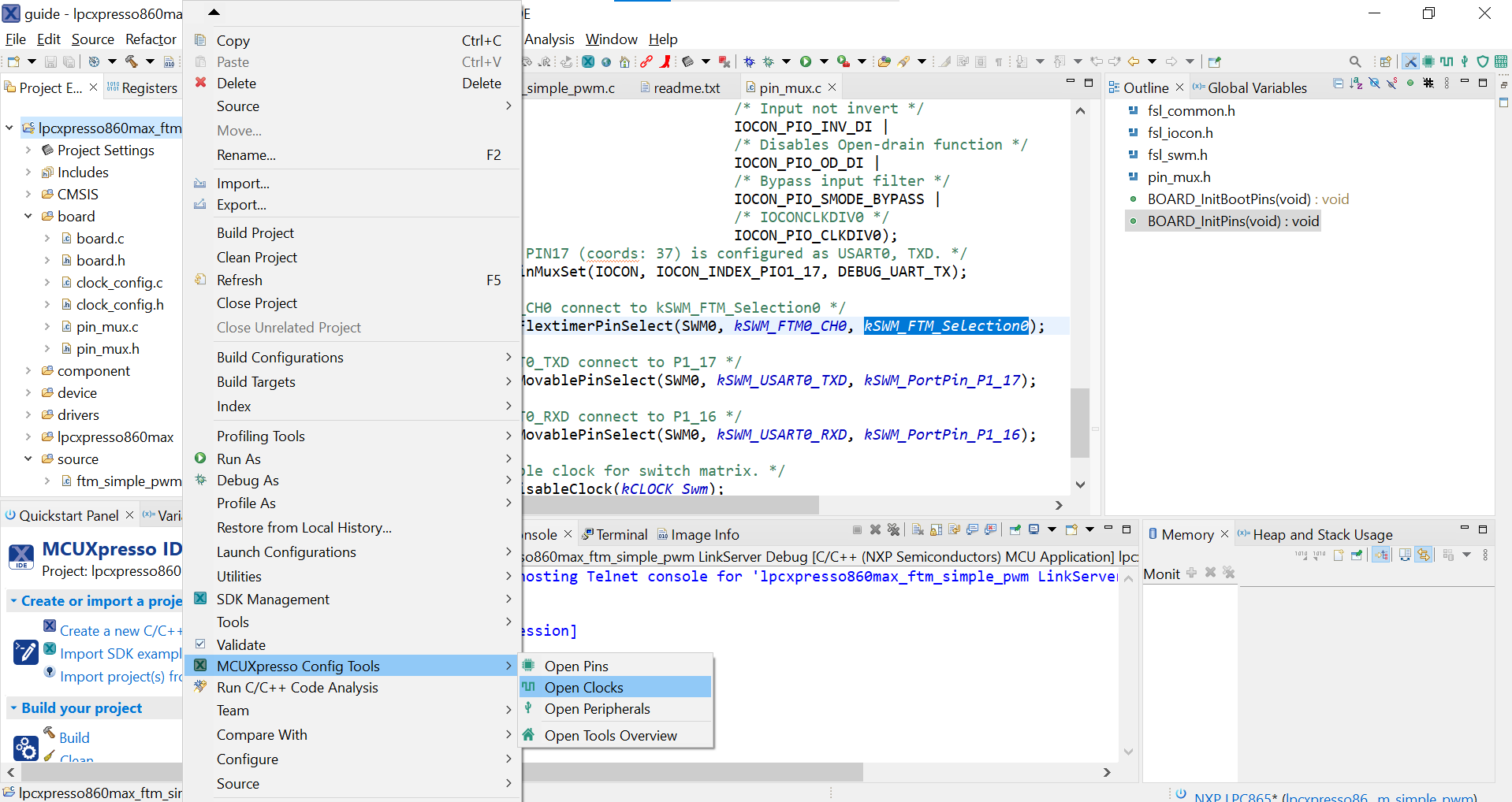
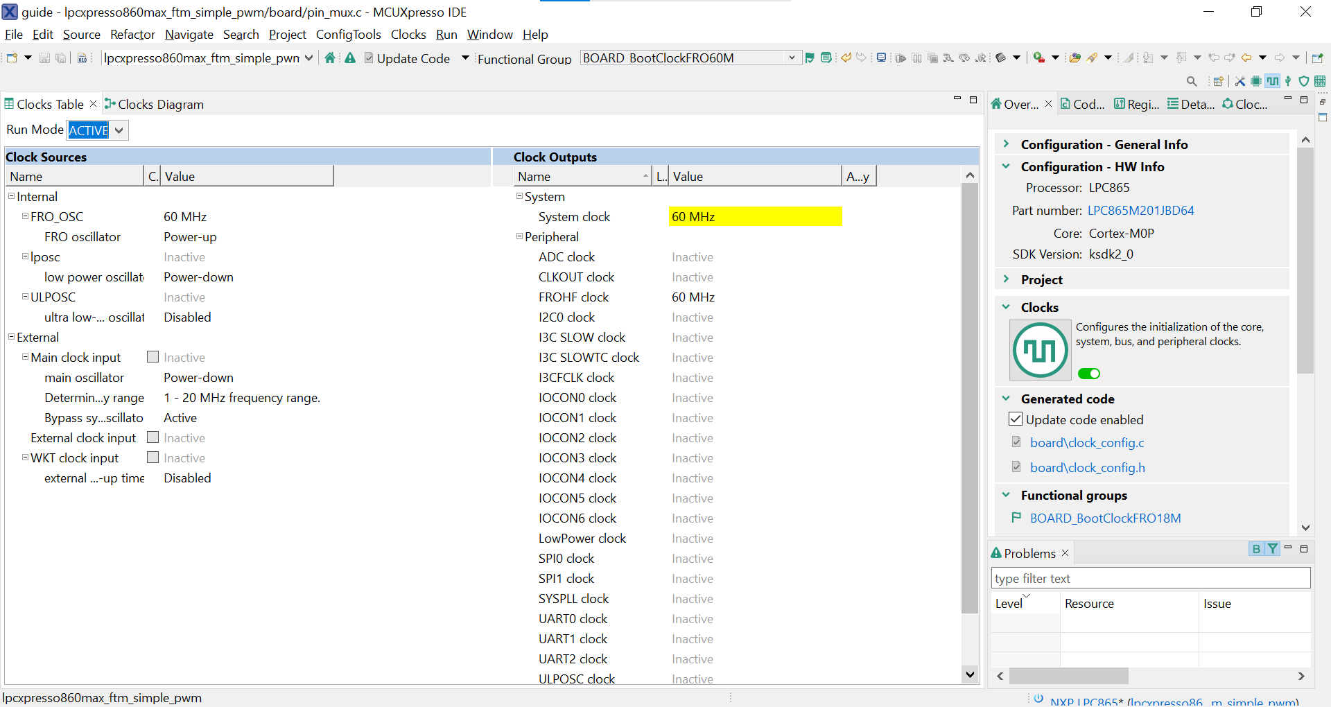
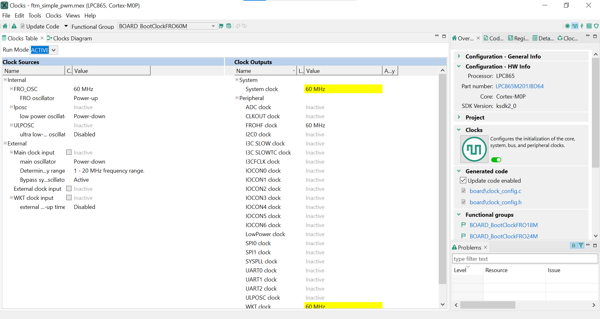
- The clock tool should now display the clock configuration for the project
To Open Clock Tools in MCUXpresso Config Tools
- In the wizard that comes up, select the “Open existing configuration” radio button, then select the project that you had clone and click on Next
- Open the clocks tool by selecting Tools → clocks from the toolbar
- The clock tool should now display the clock configuration for the PWM project
Use the Clock Tools to Modify the System Clock
- We'll use MCUXpresso IDE for the rest of the instructions, but the same steps can be done in MCUXpresso Config tools for third-party IDEs. Switch to the Clocks Diagram view by clicking the tab in the upper left corner
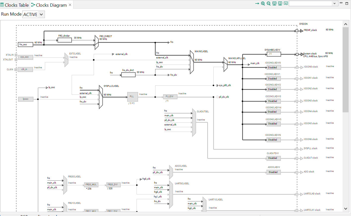
- Make sure that you are in the functional group called "
BOARD_BootClockFROH60M"
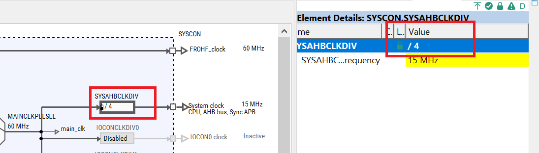
- Change the core clock frequency by clicking in the Systems Clock field and typing “4”. You'll see all the other clock values automatically change as well to adjust to this slower speed. It will look like this when done
- Now it's time to implement these changes into the project by exporting the new updated
clockmux.candclockmux.hfiles that are generated by the Pins tool. Click on Update Project in the menu bar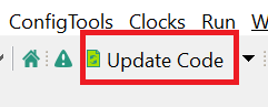
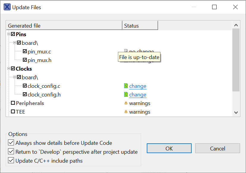
-
The screen that pops up will show the files that are changing, and you can click on “diff” to see the difference between the current file and the new file generated by the Clock tool. Click on “OK” to overwrite the new files into your project
- Build and download the project as done in the previous section
- Run the application. You could see the change of the duty cycle become much slower
- Terminate the debug session
4.4 Success
With the application modified, you will see the LPCXpresso860-MAX green LED(D2) blinking.
MCUXpresso Terminal Tutorial
MCUXpresso Terminal Tutorial
The most recent versions of MCUXpresso IDE count with a terminal emulation application. This tool can be used to display information sent from your NXP development platform's virtual serial port.
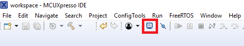
- Open the MCUXpresso IDE.
- Launch the MCUXpresso IDE terminal by clicking on the “Open a Terminal” button on the top of the IDE or press “Ctrl + Alt + Shift + T.”
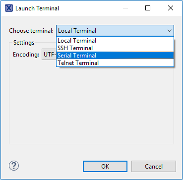
- Select Serial Terminal
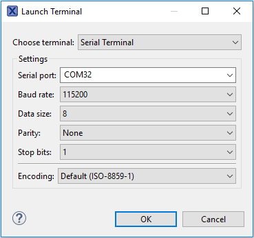
- Configure the serial port settings (using the LPC-Link2 COM port number) to 115200 baud rate, 8 data bits, no parity and 1 stop bit, then press “OK” button.
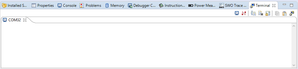
-
Verify that the connection is open. If connected, MCUXpresso IDE will look like the figure below at the Terminal view.
-
You're ready to go

Tera Term Tutorial
Tera Term Tutorial
Tera Term is a very popular open source terminal emulation application. This program can be used to display information sent from your NXP development platform's virtual serial port.
- Download Tera Term from SourceForge. After the download, run the installer and then return to this webpage to continue.
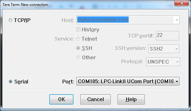
- Launch Tera Term. The first time it launches, it will show you the following dialog. Select the serial option. Assuming your board is plugged in, there should be a COM port automatically populated in the list.
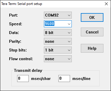
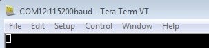
- Configure the serial port settings (using the COM port number identified earlier) to 115200 baud rate, 8 data bits, no parity and 1 stop bit. To do this, go to Setup → Serial Port and change the settings.
- Verify that the connection is open. If connected, Tera Term will show something like below in its title bar.
PuTTY Tutorial
PuTTY Tutorial
PuTTY is a popular terminal emulation application. This program can be used to display information sent from your NXP development platform's virtual serial port.
- Download PuTTY using the button below. After the download, run the installer and then return to this webpage to continue.
- Launch PuTTY by either double-clicking on the *.exe file you downloaded or from the Start menu, depending on the type of download you selected.
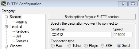
- Configure In the window that launches, select the Serial radio button and enter the COM port number that you determined earlier. Also enter the baud rate, in this case 115200.
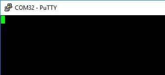
- Click Open to open the serial connection. Assuming the board is connected and you entered the correct COM port, the terminal window will open. If the configuration is not correct, PuTTY will alert you.
- You're ready to go
On this page
- 2.1
Jump Start Your Design With the MCUXpresso SDK
- 2.2
Get Your Toolchain
- 2.3
MCUXpresso Config Tools
- 2.4
Install Drivers and Update Debug Probe Firmware
- 2.5
Serial Terminal
- 3.1
Explore the MCUXpresso SDK Example Code
- 3.2
Build, Run and Debug MCUXpresso SDK Examples
- 3.3
Building and Debugging MCUXpresso SDK Examples
- 3.4
More Examples