Getting Started with the RD-UAMP-SENSOR Reference Design
Contents of this document
-
Out of the Box
-
Get Hardware
-
Configure Hardware
-
Build, Run
Sign in to save your progress. Don't have an account? Create one.

Purchase your Sub-µA Current Sensor
1. Out of the Box
The NXP analog product development boards provide an easy-to-use platform for evaluating NXP products. The boards support a range of analog, mixed-signal and power solutions. They incorporate monolithic integrated circuits and system-in-package devices that use proven high-volume technology. NXP products offer longer battery life, a smaller form factor, reduced component counts, lower cost and improved performance in powering state-of-the-art systems.
This page will guide you through the process of setting up and using the RD-UAMP- SENSOR board.
1.1 Kit contents/packing list
The RD-UAMP-SENSOR contents include:
- Assembled and tested board in an anti-static bag
- Quick Start Guide
1.2 Additional hardware
In addition to the kit contents, the following hardware is necessary or beneficial when working with this kit.
- FRDMKL25-A8471 or FRDM-K22F-AGMP03 sensor evaluation kits
1.3 Software
The software collaterals enabling RD-UAMP-SENSOR board include:
- MCUXpresso SDK based embedded software project for RD-UAMP-SENSOR board
- IoT Sensing SDK based host i/o embedded project enabling sensor tool box GUI demo (for sensors evaluation kits, for example, FRDMKL25-A8471 and FRDM-K22F- AGMP03)
- Sensor tool box windows GUI extension packages for visualizing current measurement output
1.4 User manual
Refer to UM11470, RD-UAMP-SENSOR reference design for additional details on the featured components and board configuration.
2. Get Hardware
2.1 Board description
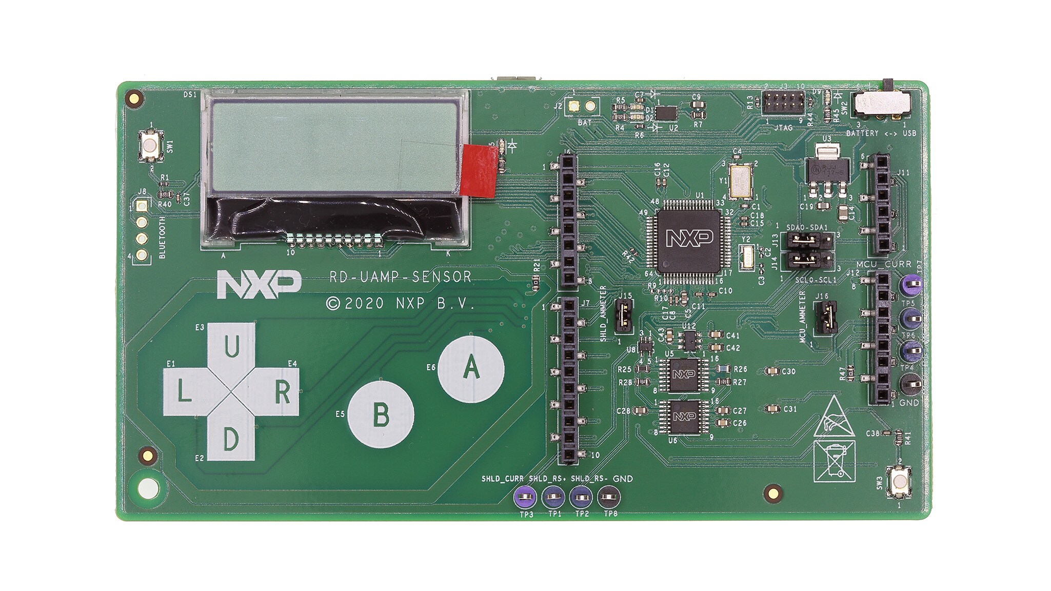
The RD-UAMP-SENSOR reference design is a Cortex-M4-based current measurement board, for use with the FRDM Development Ecosystem or any other Arduino-like development boards.
The board embeds two controllable current measurement units that allow for signal filtering, automatic and manual range switching, as well as an LCD module and capacitive buttons for quick visualization and configuration.
2.2 Board features
- Non-intrusive interfacing with any MCU board and 3.3 V shield
- Measurement of a large range of low currents: ~60 nA – 5 mA
- Multiple communication methods: LCD module, I2C sensor emulation, optional Bluetooth module, serial port / custom protocol through USB
- Integration with FRDM Sensor Toolbox (CE)
- Open-source firmware powered by FreeRTOS
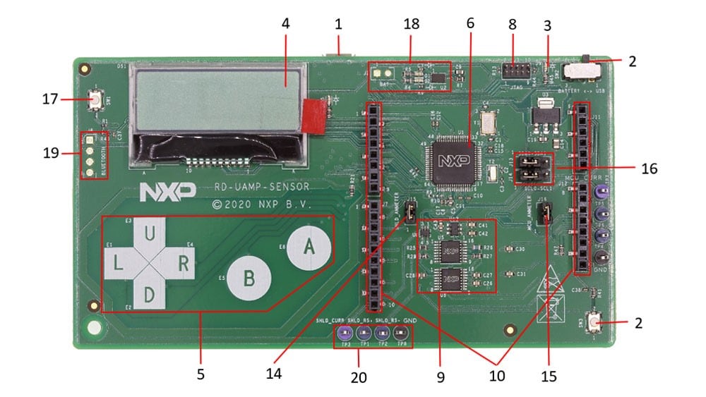
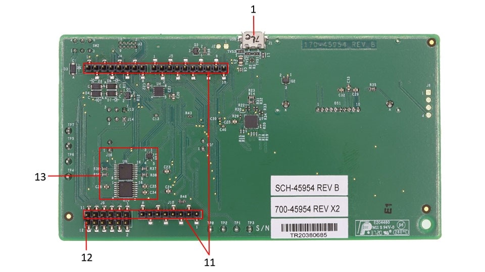
2.3 Board components
Overview of the RD-UAMP-SENSOR board


Table 1. Evaluation board component descriptions
| Number | Label | Name | Description |
|---|---|---|---|
| 1 | J1 | Micro-USB B female connector | Provides 5.0 V power supply to the board and access to K22F MCU USB pins |
| 2 | SW2 | On/Off switch |
When the board is equipped with a battery, slide to:
|
| 3 | D9 | Power indicator LED | LED turns red when the board is powered On |
| 4 | DS1 | LCD module | Displays real-time current measurement results and the various menu pages and parameters |
| 5 | E1 to E6 | Capacitive touch buttons | Allows navigation across all menu pages and parameters selection |
| 6 | U1 | K22F Cortex M4 MCU | On-board MCU running a real-time firmware to emulate a microampere current sensor |
| 7 | SW1 | Reset pushbutton | Manual reset for onboard K22F MCU |
| 8 | J3 | 10 pins JTAG header | Used to flash and debug onboard K22F MCU |
| 9 | U5, U6, U8, U12 | Sensor shield current measurement unit | Arrangement of a precision LDO, a differential amplifier, sense resistors and filtering capacitors connected with CMOS switches |
| 10 | J6, J7, J11, J12 | Sensor shield headers | Connect a sensor shield on top of the board in order to measure current |
| 11 | J4, J5, J9, J10 | FRDM board connection headers | Plug the board onto the FRDM bottom board associated to the sensor top shield |
| 12 | J9 - pin 12 | Shield current | Provides compatibility with LPCXpresso boards that incorporate the power measurement circuit for MCUXpresso IDE power measurement tool |
| 13 | U9, U10, U11 | FRDM MCU current measurement unit | Arrangement of a differential amplifier, sense resistors and filtering capacitors connected with CMOS switches |
| 14 | J15 | Header for shield ammeter | Remove jumper to measure current with an external micrometer (for verification/ calibration purpose) |
| 15 | J16 | Header for MCU ammeter | Remove jumper to measure current with an external micrometer (for verification/ calibration purpose) |
| 16 | J13, J14 | I2C selection headers | Set SDA and SCL jumpers onto pins 2-3 in order to select I2C1 lines (right position, contrary to picture) |
| 17 | SW3 | RST header pushbutton | Manual reset of the RST line (J12-pin3) |
| 18 | J2, U2, D1, D2 | Battery connector, charger and LEDs | Simply connect a LiPo/Lion battery to J2 in order to operate the board autonomously and even wirelessly with a BT module |
| 19 | J8 | 4 pins UART/Bluetooth connector | Can be used to connect a serial interface or Bluetooth module (necessitates K22F firmware customization) |
| 20 | TP1 to TP8 | Test points | Easy access to current sense amplifier inputs and output |
2.4 Additional board support
Refer to UM11470, RD-UAMP-SENSOR reference design for additional details on the featured components.
3. Configure Hardware

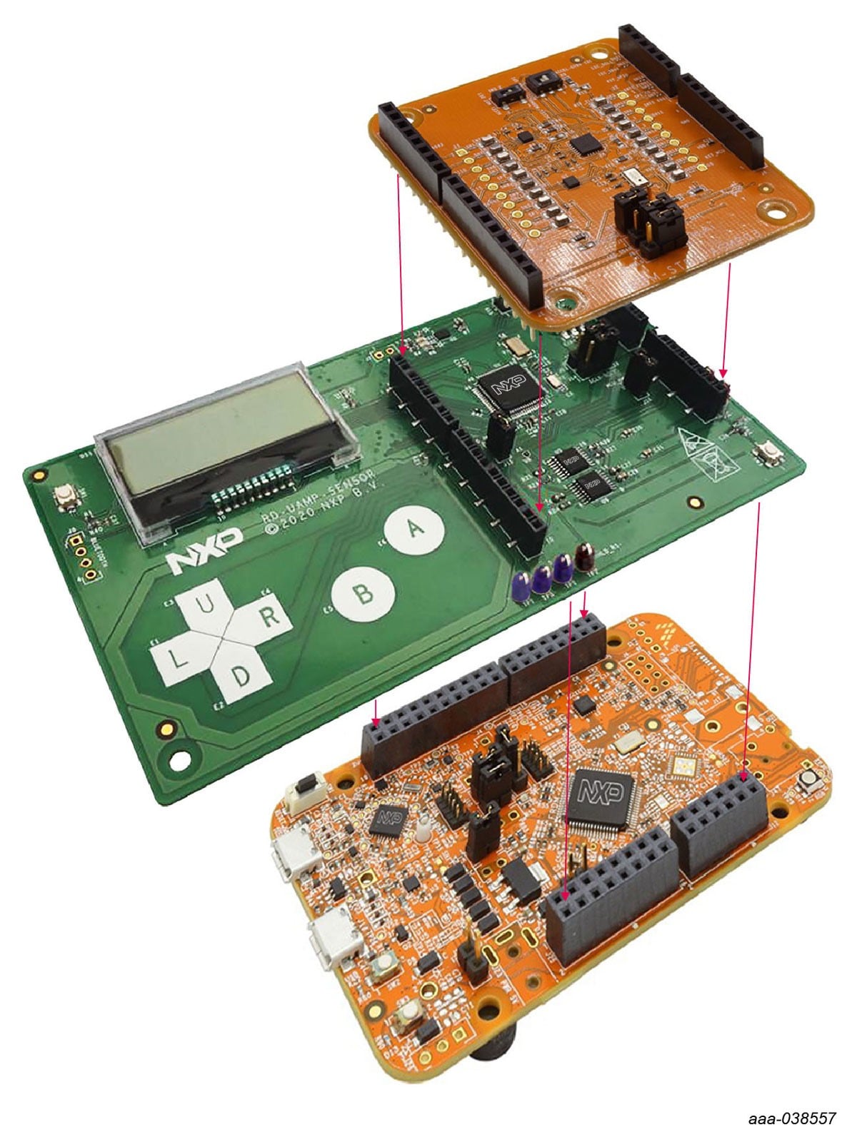
The RD-UAMP-SENSOR reference design is designed to interface with any existing 3.3 V MCU and shield combo, such as the NXP FRDM sensor development kits.
Note: RD-UAMP-SENSOR board has been tested with FRDMKL25-A8471 (FRDM-KL25Z MCU and FRDM-STBC-A8471 shield board) and FRDM-K22F-AGMP03 (FRDM-K22F MCU and FRDM-STBC-AGMP03 shield board) sensor evaluation kits.
The RD-UAMP-SENSOR board simply plugs in between the MCU and shield, mirroring all pins except for the 3.3 V supplies that now go through the current measurement units.
Note: The MCU current measurement is possible only when powered from the RD- UAMP-SENSOR’s onboard USB or battery.
3.1 Additional board support
Refer to UM11470, RD-UAMP-SENSOR reference design user manual for additional details on the hardware configuration.
4. Build, Run
Go to RD-UAMP-SENSOR tool summary page to download required software collaterals.
Prerequisite:
- Install STB-CE software
- Download and install MCUXpresso SDK for FRDMKL25-A8471 and FRDM-K22F-AGMP03
- Install MCUXpresso IDE (to be able to build and run embedded projects)
4.1 Additional software support
Refer to UM11470, RD-UAMP-SENSOR reference design user manual for additional details on the hardware configuration.
Design Resources
Support
Forums
Connect with other engineers and get expert advice on designing with the RD-UAMP-SENSOR on one of our community sites.