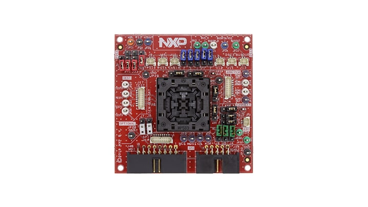
Getting Started with the SEN-GEN6-SKT Evaluation Board
Contents of this document
-
Out of the Box
-
Get Hardware
-
Configure Hardware
Sign in to save your progress. Don't have an account? Create one.
Purchase your SEN-GEN6-SKT | Socket Board for FXLS9 and FXP7 Sensors
1. Out of the Box
The NXP analog product development boards provide an easy-to-use platform for evaluating NXP products. The boards support a range of analog, mixed-signal and power solutions. They incorporate monolithic integrated circuits and system-in-package devices that use proven high-volume technology. NXP products offer longer battery life, a smaller form factor, reduced component counts, lower cost and improved performance in powering state-of-the-art systems.
This page will guide you through the process of setting up and using the SEN-GEN6-SKT board.
1.1 Kit contents/packing list
The SEN-GEN6-SKT contents include:
- One automotive Sensor Socket board (SEN-GEN6-SKT)
- Four red jumpers
- Two white jumpers
- Three green jumpers
- Seven purple jumpers
1.2 Additional hardware
The SEN-GEN6-SKT kit can be coupled with SEN-SPI-BOX.
1.3 User manual
Refer to UM11559, SEN-GEN6-SKT board for additional details on the featured components and board configuration.
2. Get Hardware
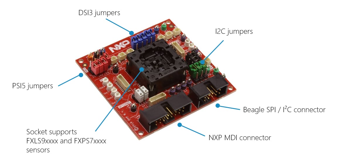
2.1 Board description
The SEN-GEN6-SKT board is a socket kit designed to evaluate the FXLS9xxxx and FXPS7xxxx sensors. The board supports different communication configurations such as SPI, I²C, DSI3 or PSI5. Before inserting a device into the socket, make sure you have properly configured the board to support the desired protocol.
2.2 Board features
- Supports both FXLS9xxxx and FXPS7xxxx sensors
- Supports SPI, I2C, DSI3 and PSI5
- Dedicated Beagle and NXP MDI interfaces
- Colored test points for scope probing
2.3 Board components
2.4 Additional board support
Refer to UM11559, SEN-GEN6-SKT board for additional details on the featured components.
3. Configure Hardware
The board supports the FXLS9xxxx and FXPS7xxxx sensor families.
For easier board configuration, the jumpers have been colored per category/protocol. They are listed below:
- Sensor compatibility or power supply related: black
- I2C: green
- DSI3: blue
- PSI5: red
- SPI: N/A
By default, the board is configured for FXLS9xxxx devices in SPI mode. However, the configuration can easily be modified using the jumpers.
By default, most jumpers are floating. Floating means they are attached to their proper connector but remain unconnected. The reference to "DNP" means “Do not populate”, meaning it can be removed or unshorted.
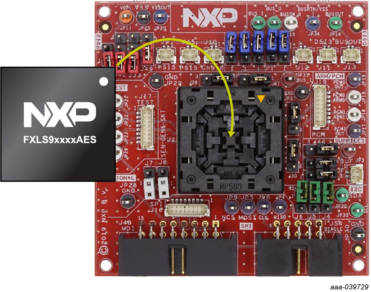
3.1 Insert the sensor into the socket
The following figure illustrates the proper way to insert the sensor into the socket. For proper connection, align the circle on the IC to the arrowhead (identified in yellow) on the mounting socket.
3.2 Connect the board to a compatible ECU
The SEN-SPI-BOX has two dedicated interfaces suitable for SPI and I2C communications, an MDI connector and a Beagle connector. The NXP MDI connector supports the SEN-SPI-BOX kit. The Beagle connector is an industrial standard and may be coupled to any Beagle compatible analyzer.
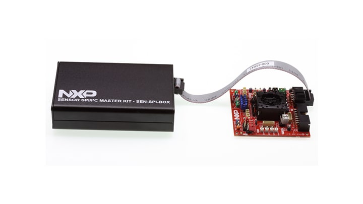
For DSI3 and PSI5 support, the SEN-SPI-BOX can be used with a dedicated NXP adapter (SEN-DSI3-ADAPTER and SEN-PSI5-ADAPTER).
3.3 Additional board support
Refer to UM11559, SEN-GEN6-SKT board user manual for additional details on the hardware configuration.
Design Resources
Board Documents
Support
Forums
Connect with other engineers and get expert advice on designing with the SEN-GEN6-SKT on one of our community sites.