- No Longer Manufactured
- P87C52X2FBD
80C51 8-Bit Microcontroller Family
The Philips microcontrollers described in this data sheet are high-performance static 80C51 designs incorporating Philips? high-density CMOS technology with operation from 2.7 V to 5.5 V. They support both 6-clock and 12-clock operation.
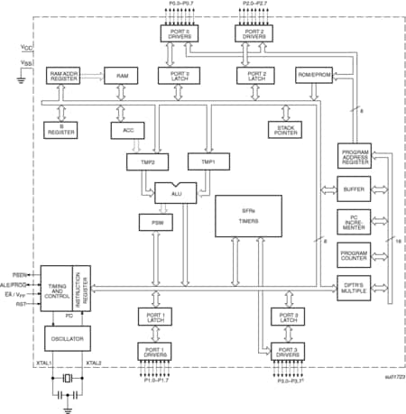
The P8xC31X2/51X2 and P8xC32X2/52X2/54X2/58X2 contain 128 byte RAM and 256 byte RAM respectively, 32 I/O lines, three 16-bit counter/timers, a six-source, four-priority level nested interrupt structure, a serial I/O port for either multi-processor communications, I/O expansion or full duplex UART, and on-chip oscillator and clock circuits.
In addition, the devices are low power static designs which offer a wide range of operating frequencies down to zero. Two software selectable modes of power reduction ? idle mode and power-down mode ? are available. The idle mode freezes the CPU while allowing the RAM, timers, serial port, and interrupt system to continue functioning. The power-down mode saves the RAM contents but freezes the oscillator, causing all other chip functions to be inoperative. Since the design is static, the clock can be stopped without loss of user data. Then the execution can be resumed from the point the clock was stopped.
Product Details
Features
- 80C51 Central Processing Unit
- 4 kbytes ROM/EPROM (P80/P87C51X2)
- 8 kbytes ROM/EPROM (P80/P87C52X2)
- 16 kbytes ROM/EPROM (P80/P87C54X2)
- 32 kbytes ROM/EPROM (P80/P87C58X2)
- 128 byte RAM (P80/P87C51X2 and P80C31X2)
- 256 byte RAM (P80/P87C52/54X2/58X2 and P80C32X2)
- Boolean processor
- Fully static operation
- Low voltage (2.7 V to 5.5 V at 16 MHz) operation
- 12-clock operation with selectable 6-clock operation (via software or via parallel programmer)
- Memory addressing capability
- Up to 64 kbytes ROM and 64 kbytes RAM
- Power control modes:
- Clock can be stopped and resumed
- Idle mode
- Power-down mode
- CMOS and TTL compatible
- Two speed ranges at VCC = 5 V
- 0 to 30 MHz with 6-clock operation
- 0 to 33 MHz with 12-clock operation
- PLCC, DIP, TSSOP or LQFP packages
- Extended temperature ranges
- Dual Data Pointers
- Security bits:
- ROM (2 bits)
- OTP (3 bits)
- Encryption array - 64 bytes
- Four interrupt priority levels
- Six interrupt sources
- Four 8-bit I/O ports
- Full-duplex enhanced UART
- Framing error detection
- Automatic address recognition
- Three 16-bit timers/counters T0, T1 (standard 80C51) and additional T2 (capture and compare)
- Programmable clock-out pin
- Asynchronous port reset
- Low EMI (inhibit ALE, slew rate controlled outputs, and 6-clock mode)
- Wake-up from Power Down by an external interrupt.
Documentation
Quick reference to our documentation types.
3 documents
-
Package Information
plastic low profile quad flat package; 44 leads; body 10 x 10 x 1.4 mm
-
Supporting Information
Footprint for wave soldering

