- No Longer Manufactured
- PCF2113x
LCD Controllers/Drivers
- This page contains information on a product that is no longer manufactured (discontinued). Specifications and information herein are available for historical reference only.
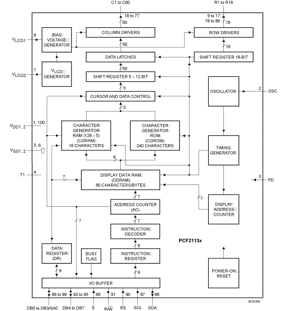
The PCF2113x is a low-power CMOS LCD controller and driver, designed to drive a dot matrix LCD display of 2 lines of 12 characters or 1 line of 24 characters with 5 x 8 dot format. All necessary functions for the display are provided in a single chip, including on-chip generation of LCD bias voltages, resulting in a minimum of external components and lower system current consumption. The PCF2113x interfaces to most microcontrollers via a 4-bit or 8-bit bus or via the 2-wire I²C-bus. The chip contains a character generator and displays alphanumeric and kana (Japanese) characters.
The letter 'x' in PCF2113x characterizes the built-in character set. Various character sets can be manufactured on request.
Product Details
Features
Key Features
- Single-chip LCD controller/driver
- 2-line display of up to 12 characters + 120 icons, or 1-line display of up to 24 characters + 120 icons
- 5 x 7 character format plus cursor; 5 x 8 for kana (Japanese) and user-defined symbols
- Icon mode for e.g. additional segment display section: reduced current consumption while displaying icons only
- Icon blink function
- Display data RAM: 80 characters
- Character generator ROM: 240 characters of 5 x 8 dots
- Character generator RAM: 16 characters of 5 x 8 dots; 3 characters used to drive 120 icons, 6 characters used if icon blink feature is used in application
- 4-bit or 8-bit parallel bus and 2-wire I²C-bus interface
- 18 row and 60 column outputs
- Multiplex rates (MUX) 1:18 (for normal operation), 1:9 (for single-line operation) and 1:2 (for Icon-only mode)
- Uses common 11 code instruction set (extended)
- Logic supply voltage range VDD1 - VSS1 = 1.8 V to 5.5 V (chip may be driven with two battery cells)
- VLCD generator supply voltage range VDD2 - VSS2 = 2.2 V to 4.0 V
- Display supply voltage range VLCD - VSS2 = 2.2 V to 6.5 V
- Direct mode to save current consumption for icon mode and MUX 1:9 (depending on VDD2 and LCD liquid properties)
- CMOS compatible
Very Low current consumption (20 uA to 200 uA)
- Icon mode: <25 uA
- Power-down mode: < 2 uA
On-Chip
- Configurable 4, 3 or 2 voltage multiplier, generating LCD supply voltage VLCD, independent of VDD, programmable by instruction (external supply also possible)
- Temperature compensation of on-chip generated VLCD: -0.16 pct/K to -0.24 pct/K (programmable by instruction)
- Generation of intermediate LCD bias voltages
- Oscillator requires no external components (external clock also possible)
Note
-
Icon mode is a way to save current. When only icons are displayed (i.e. only the lower two rows are active), a much lower operating voltage VLCD can be used and the switching frequency of the LCD outputs is reduced. In most applications it is possible to use VDD as VLCD