Application Note (2)
Data Sheet (1)
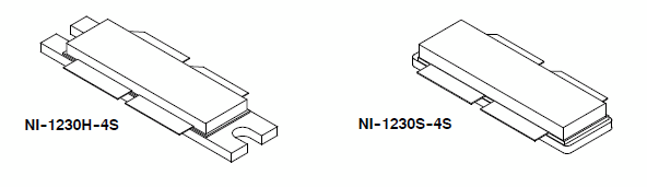
Package Information (2)
Supporting Information (1)
-
RF Military High Power Avionics Devices[MILITARY_HIGH_POWER_RADAR_TRN_SI]
| Frequency (MHz) |
Signal Type | Pout (W) |
Gps (dB) |
ηD (%) |
| 1030(1) | Pulse (128 µsec, 10% Duty Cycle) | 1300 Peak | 18.9 | 56.0 |
| 1090(1) | 1100 Peak | 18.8 | 57.9 |
| Frequency (MHz) |
Signal Type | Pout (W) |
Gps (dB) |
ηD (%) |
| 1030(2) | Pulse (128 µsec, 10% Duty Cycle) | 1300 Peak | 18.2 | 58.1 |
| Frequency (MHz) |
Signal Type | VSWR | Pin (W) |
Test Voltage |
Result |
| 1030(2) | Pulse (128 µsec, 10% Duty Cycle) | > 10:1 at all Phase Angles | 40 (3 dB Overdrive) | 50 | No Device Degradation |
|
|
|
|
|
|
|
|---|---|---|---|---|---|
|
|
|
|
|
|
|
|
|
|
|
|
|
|
|
|
|
|
|
|
|
|
|
|
|
|
|
|
|
|
|
|
|
|
|
|
|
|
|
|
|
|
|
|
|
|
|
|
|
|
|
|
|
|
|
|
|
|
|
|
|
|
|
|
|
|
|
|
|
|
Quick reference to our documentation types
6 documents
Compact List
5 design files
Receive the full breakdown. See the product footprint and more in the eCad file.