Getting Started with MCSPTR2AK396 Development Kit
Contents of this document
-
Out of the Box
-
Get Software
-
Plug It In
-
Build, Run
Sign in to save your progress. Don't have an account? Create one.
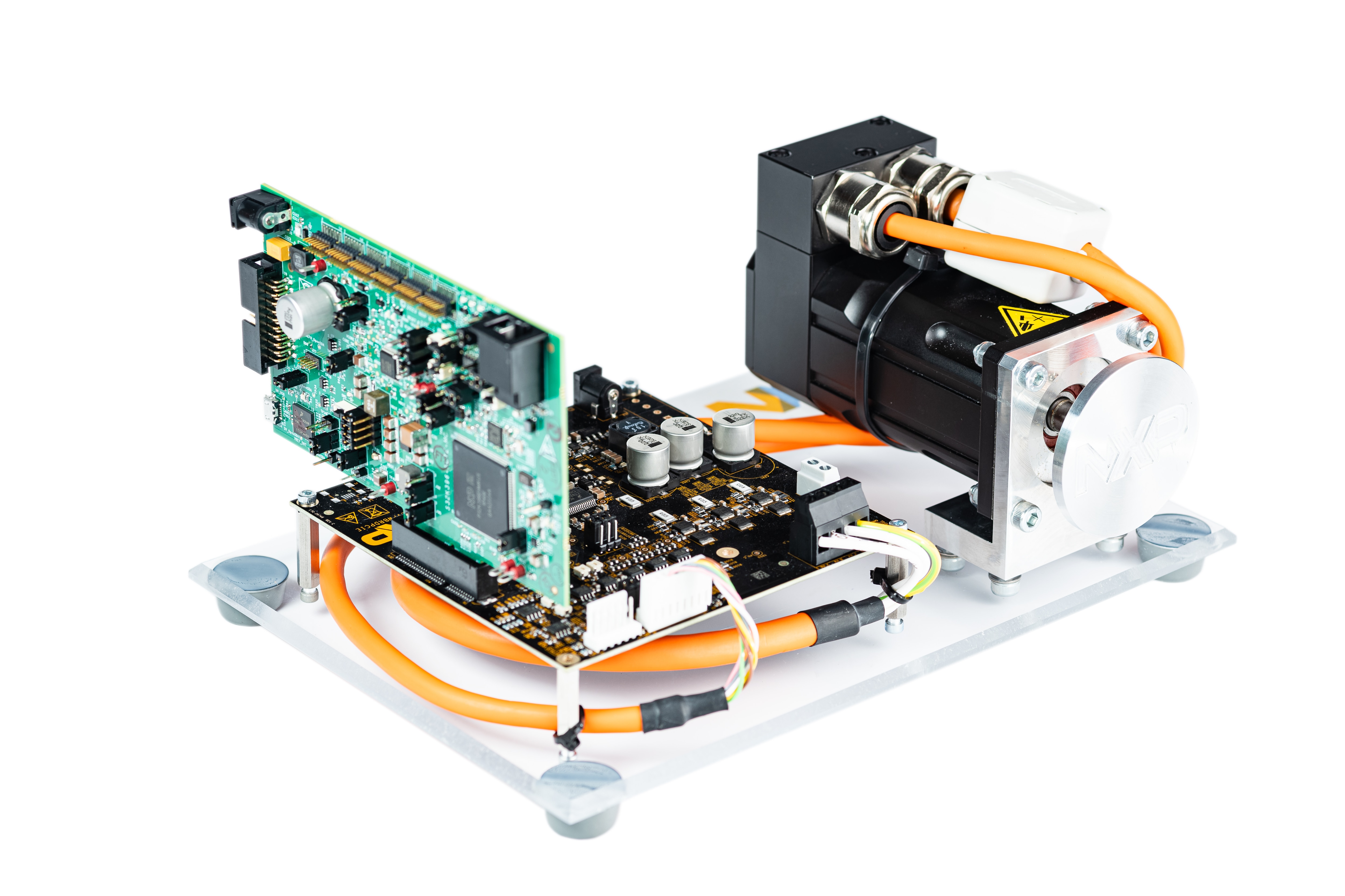
Purchase your S32K396 BLDC/PMSM Development Kit
1. Out of the Box
NXP's MCSPTR2AK396 Low-Voltage Motor Control Development Kit is designed for development of low-voltage motor control applications using the S32K396 automotive microcontroller.
This guide will walk you through the process of setting up and using the 3-Phase Permanent Magnet Synchronous Motor Control Development Kit with S32K396 (MCSPTR2AK396).
This guide also covers software (SW) installation for MCSPTR2AK396 motor control application software MCSPTR2AK396-SW.exe in revision 2.0. For MCSPTR2AK396-SW version 2.0, please refer to the MCSPTR2AK396 Getting Started webpage for software set.
1.1 MCSPTR2AK396 Overview
This section will familiarize you with the contents of this development kit.
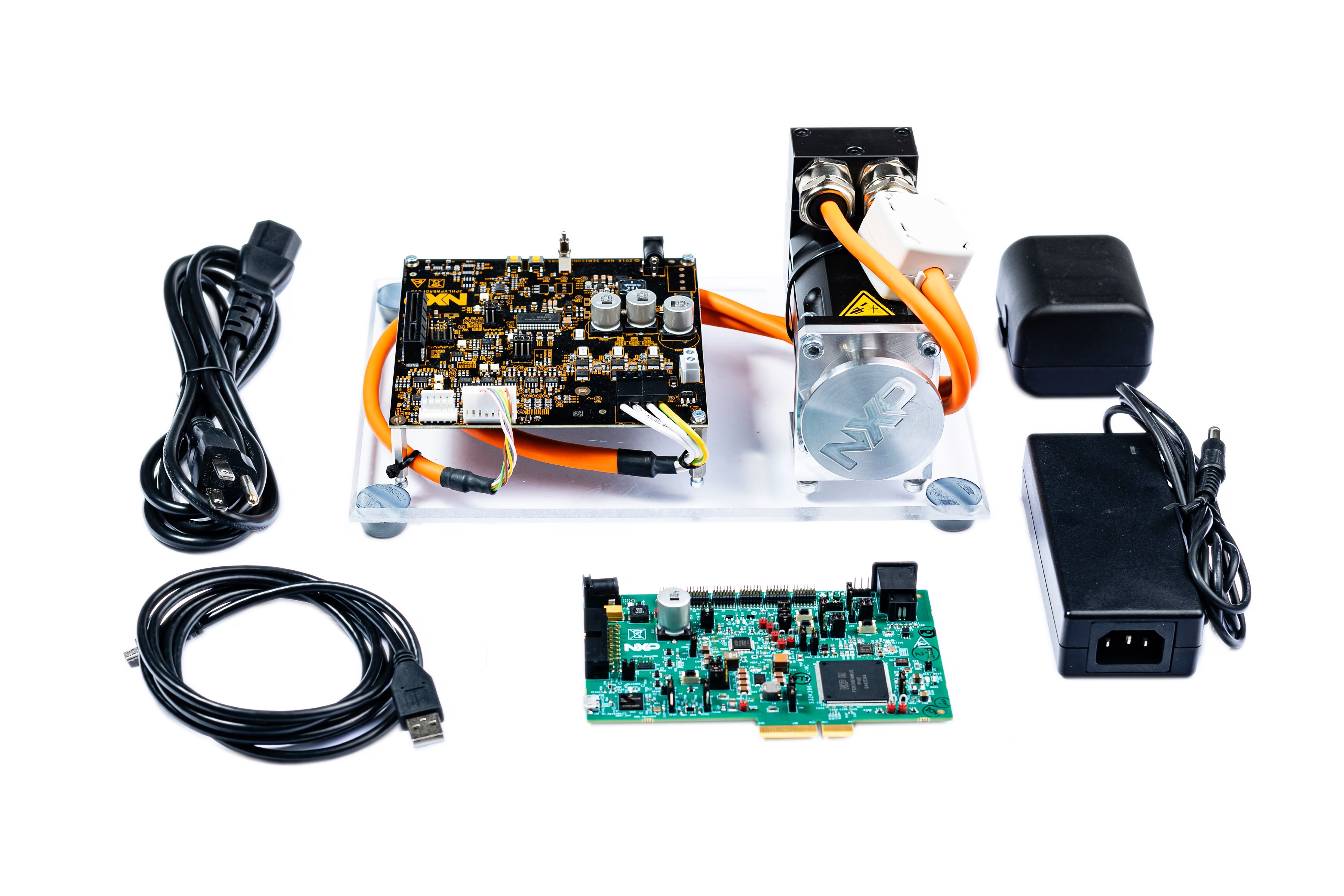
- S32K396-Peripheral Component Interconnect Express (PCIe) controller board
- 3-phase permanent magnet synchronous motor/brushless direct current
- PMSM/BLDC low-voltage power stage based on the MC33937A pre-driver integrated circuit
- Micro USB cable
- +24 VDC power supply
- Universal adapter
- PSE power cord
- 3 phase PMSM motor with resolver, 30 V per phase, 3000 RPM, 0.32 Nm, 95 W, 5.2 A
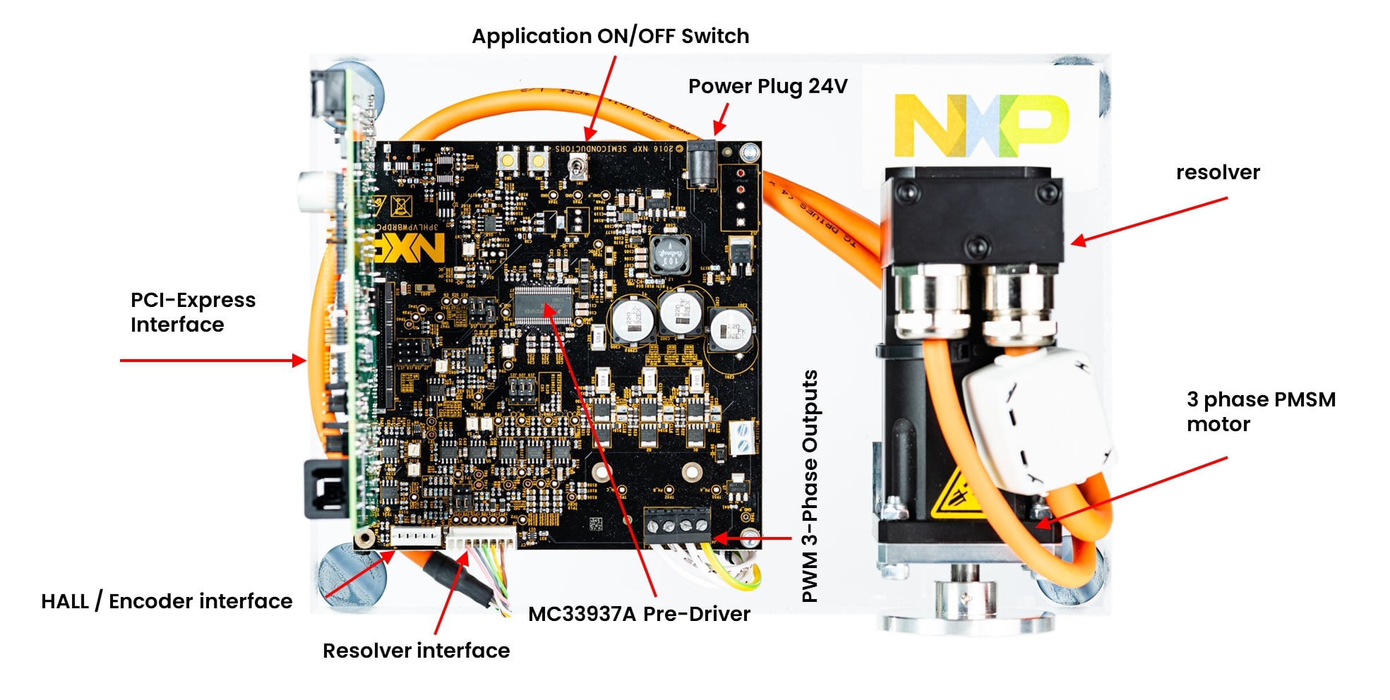
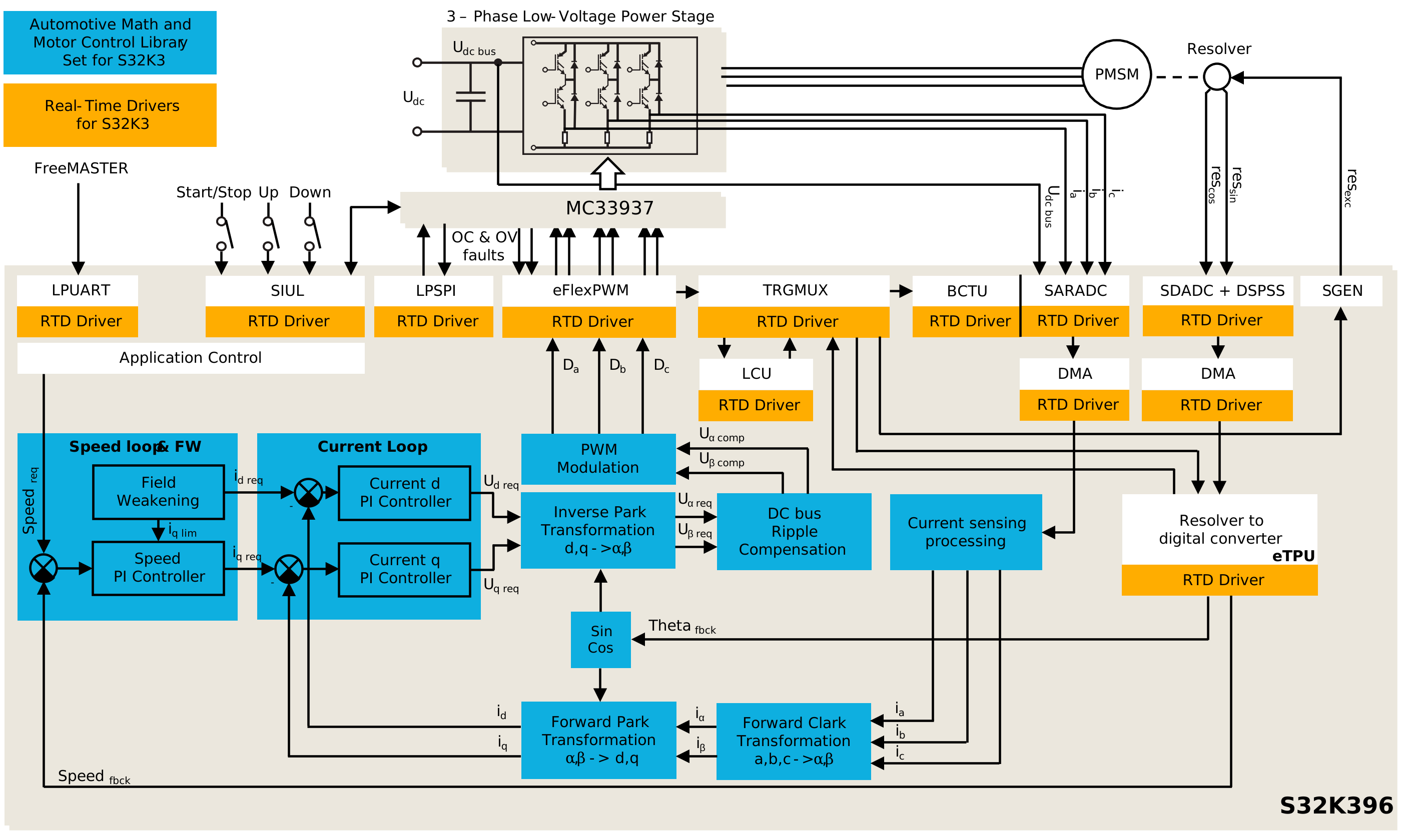
1.2 Get Familiar with the Boards
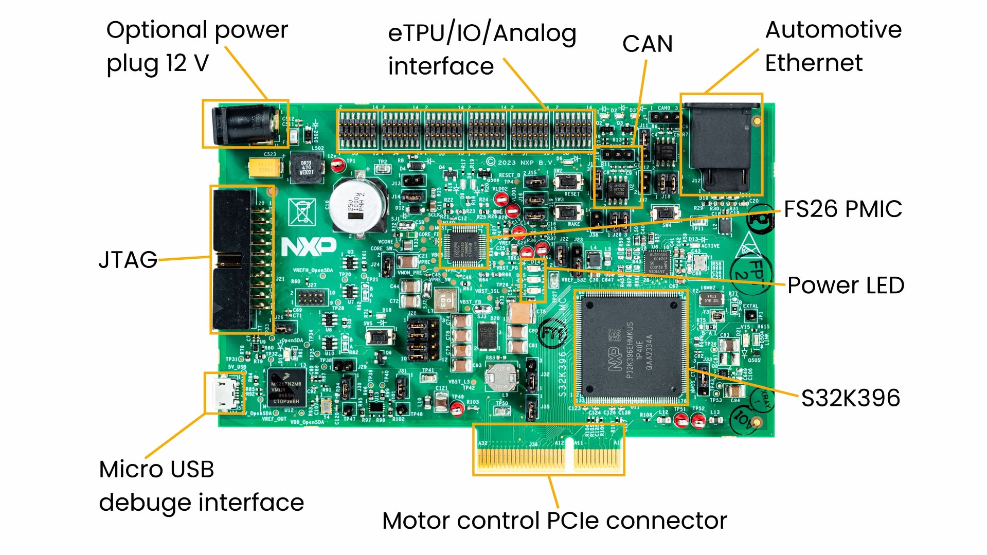
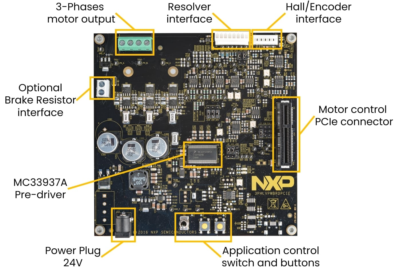
2. Get Software
Sign in at nxp.com with your credentials.
2.1 Select SW packages from Automotive Software Package Manager
Open Automotive Software Package Manager and select S32K3 device.
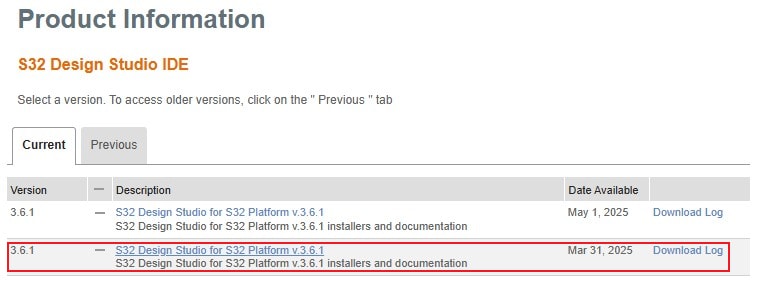
Unfold the FRDM Automotive Board Installation Package bundle and check S32 Design Studio, Real-Time Drivers and FreeMASTER software. Other SW packages are optional.
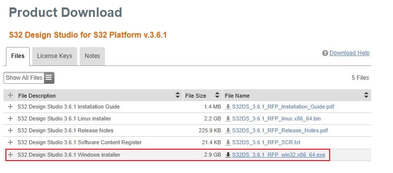
Click on the Generate Bundle Installer button at the end of the page.

Follow the wizard instructions for Export Control and SW License Agreement (need to scroll whole text down before accepting). After that, you may close the window. Installer and Installer User Manual download will start automatically in a few moments.

The FRDM Automotive Board Installation Package bundle allows to enable automatic installation and configuration sw without any interaction. That simplifies the installation procedure.

2.2 Add GCC Toolchain Version 10.2
Latest version of the S32 Design Studio contains GCC toolchain only in version 11.4. For full compatibility with RTD, you need to install GCC also in version 10.2.
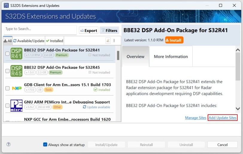
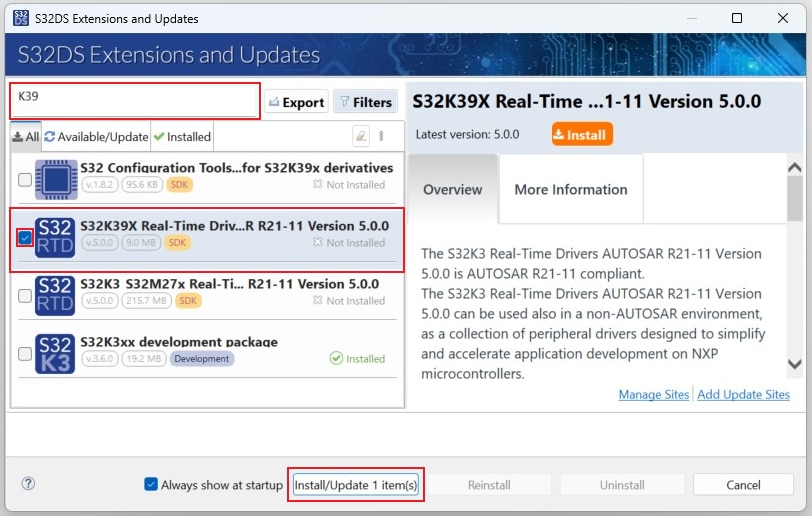
In S32 Design Studio, go to Help → S32DS Extensions and Updates from the top menu to open the S32DS Extensions and Updates dialogue where you may install it.
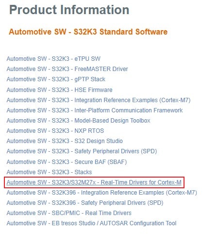
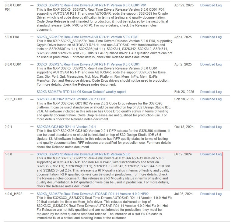
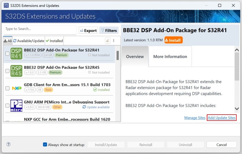
Note: Any other optional sw might be downloaded from the S32K3 Standard Software Package or S32K3 Reference Software Package. In S32DS, go to Help → S32DS Extensions and Updates from the top menu to open the S32DS Extensions and Updates dialogue where you click Add Update Sites link. Or use the drag&drop option - drag downloaded updatesite file and drop on the S32DS Extensions and Updates menu. Added sw package will also be automatically selected for following installation.

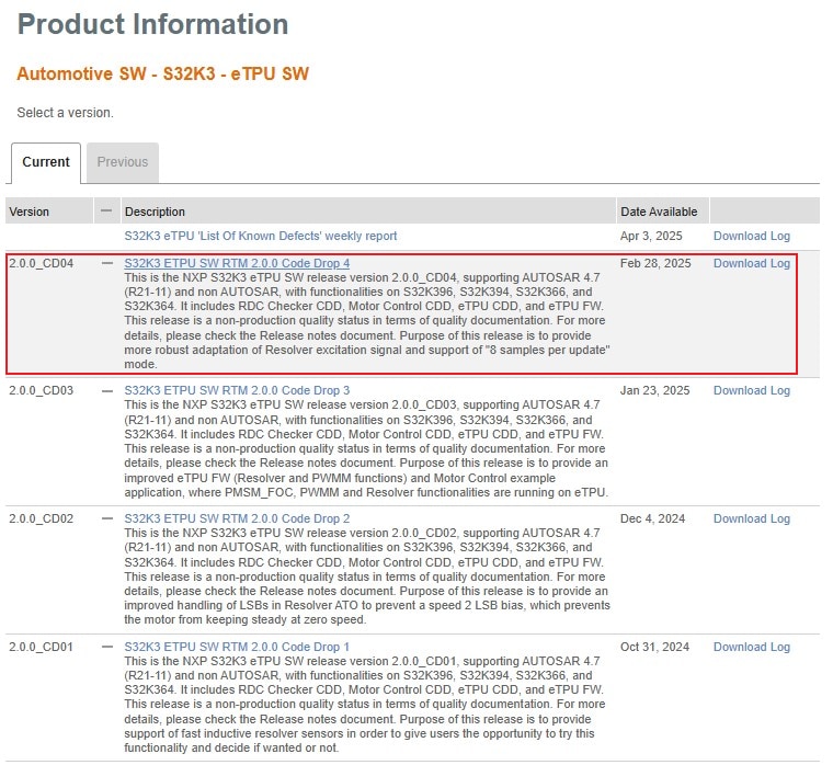
2.4 Install eTPU SW
In S32DS, go to Help → S32DS Extensions and Updates from the top menu to open the S32DS Extensions and Updates dialogue.
Click Add Update Sites and browse for downloaded eTPU SW updatesite file or use the drag&drop option - drag downloaded updatesite file and drop on S32DS Extensions and Updates menu. Added sw package will also be automatically selected for following installation.
2.5 Get FreeMASTER Application Tool for Real-Time Debugging
Download and install the FreeMASTER application tool for real-time debugging.
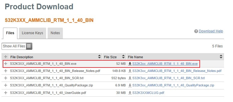
2.6 Get Automotive Math and motor Control Library (AMMCLib) Set
Download and install AMMCLib for S32K3xx.


2.7 Download the Development Kit Application Software
Download and install the MCSTR2AK396 motor control application software package.

3. Plug It In
3.1 Check Default Jumper Positions
Check the default jumper positions at the 3PHLVPWBRDPCIE power stage board
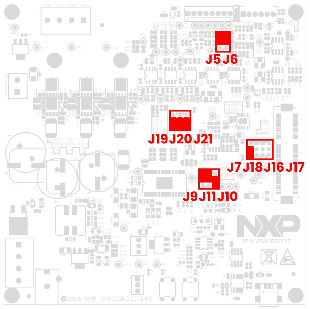
| 3PHLVPWBRDPCIE Default Jumper Settings | ||
|---|---|---|
| Jumper | State | Notes |
J5 |
2-3 | Resolver S4 output routed to operational amplifier |
J6 |
2-3 | Resolver S3 output routed to operational amplifier |
J7 |
2-3 | Resolver excitation signal from TM5 signal at PCIe connector |
J9 |
1-2 | DC BUS current sensing signal measured via operation amplifier |
J10 |
2-3 | VREF as voltage source for overcurrent threshold potentiometer |
J11 |
1-2 | External overcurrent fault comparator |
J16 |
OPEN | Zero-Cross detection disconnected |
J17 |
OPEN | Zero-Cross detection disconnected |
J18 |
OPEN | Zero-Cross detection disconnected |
J19 |
1-2 | Phase A current signal routed to AN1 signal at PCIe connector |
J20 |
1-2 | Phase B current signal routed to AN3 signal at PCIe connector |
J21 |
1-2 | Phase C current signal routed to AN5 signal at PCIe connector |
Check the default jumper positions at the S32K396-PCIE-MC controller board
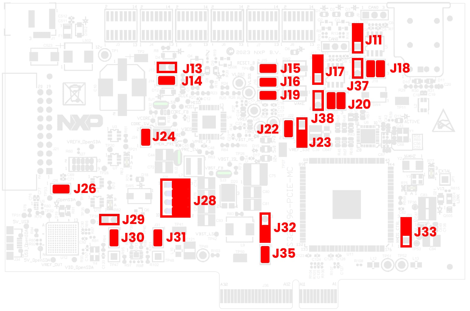
| S32K396-PCIE-MC Default Jumper Settings | ||
|---|---|---|
| Jumper | State | Notes |
J11 |
2-3 | CAN0 Transceiver STB signal pulled down |
J13 |
OPEN | FS26_VDEBUG signal generated - FS26 starts in debug mode |
J14 |
CLOSED | FS26_VDEBUG signal derived from VBOS signal |
J15 |
CLOSED | RESET SW2 connected to RESET_B signal |
J16 |
CLOSED | External wake-up signal connected to MCU |
J17 |
2-3 | CAN3 Transceiver STB signal pulled down |
J18 |
1-2, 3-4 | CAN0_TX and CAN0_RX signals routed to on-board CAN transceiver |
J19 |
CLOSED | Functional Safety signals FS0B and FS1B connected |
J20 |
1-2, 3-4 | CAN3_TX and CAN0_RX signals routed to on-board CAN transceiver |
J22 |
CLOSED | RESET_B signal connected as wake-up signal to FS26 |
J23 |
2-3 | VHREF_H voltage connected to VDD_HV_A |
J24 |
CLOSED | RESET_B signal connected to 20-pin JTAG connector |
J26 |
CLOSED | VDD_JTAG signal present at 20-pin JTAG connector |
J28 |
2-3, 5-6, 8-9, 11-12 | JTAG signals routed to S32K3 on-board debugger |
J29 |
OPEN | External RESET signal pins |
J30 |
CLOSED | LPUART2_TX signal connected to S32K3 on-board debugger |
J31 |
1-2 | LPUART2_RX signal connected to S32K3 on-board debugger |
J32 |
1-2 | Sine Wave Generator 1 routed to TM5 signal at PCIe connector |
J33 |
2-3 | V15 voltage regulated by external NMOS transistor |
J35 |
CLOSED | PTB11 connected to TM3 signal at PCIe connector |
J37 |
OPEN | CAN0 Transceiver STB signal not connected to MCU |
J38 |
1-2 | CAN3 Transceiver STB signal not connected to MCU |
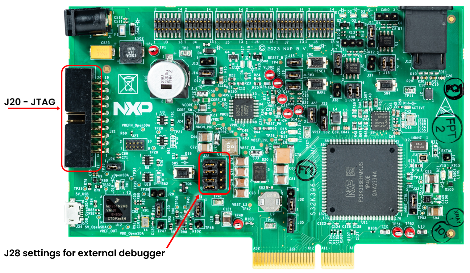
In case of using an external JTAG debug probe via J20 connector, change the settings of J28 to 1-2, 4-5, 7-8, 10-11.
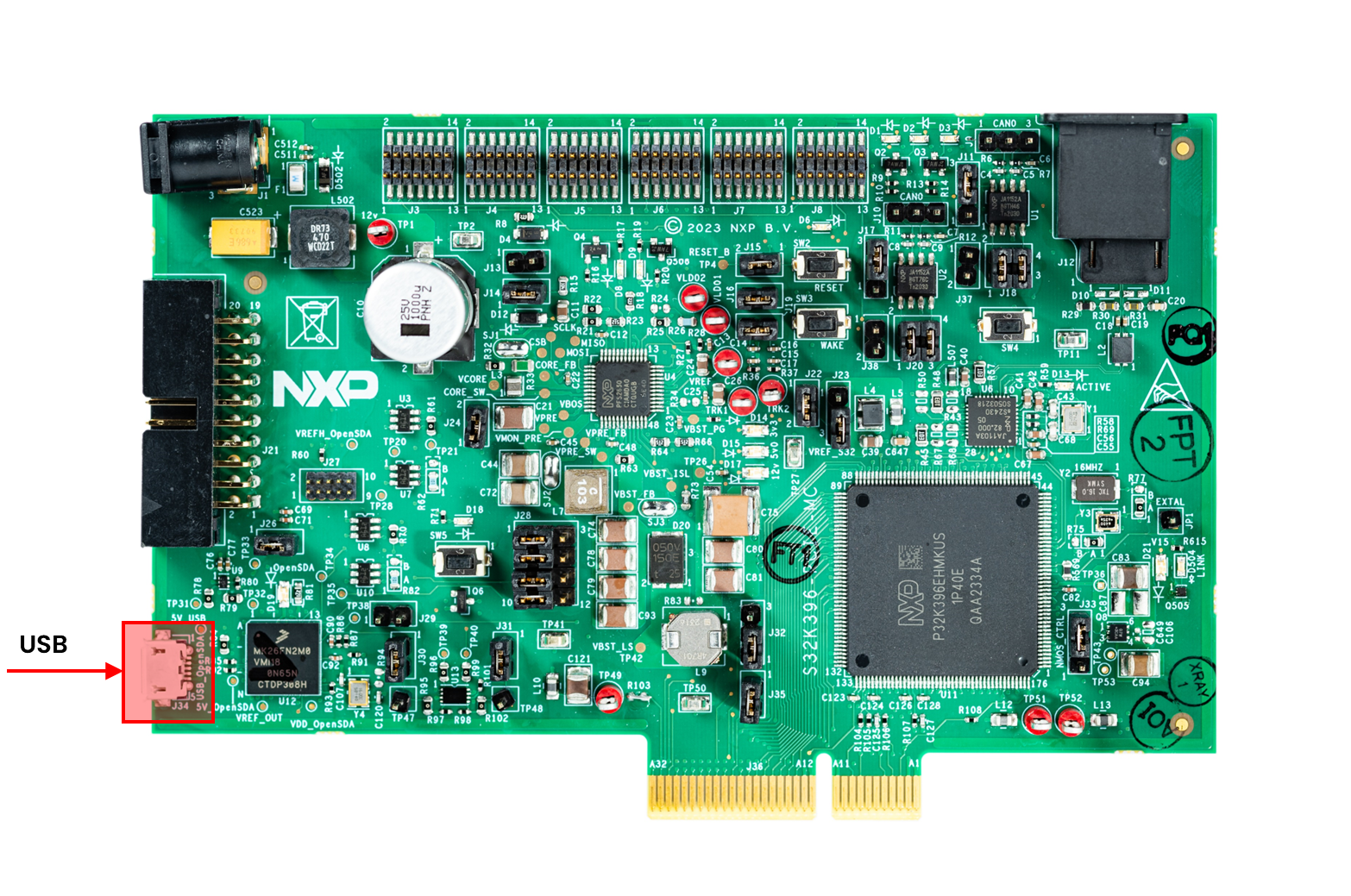
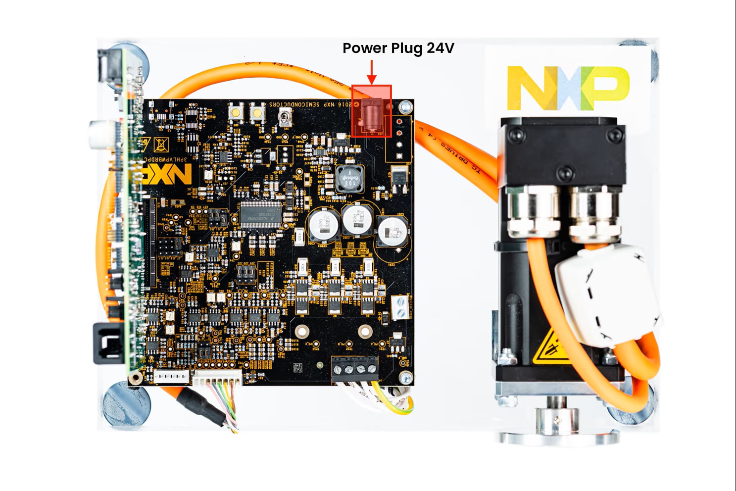
3.2 Assemble the Boards
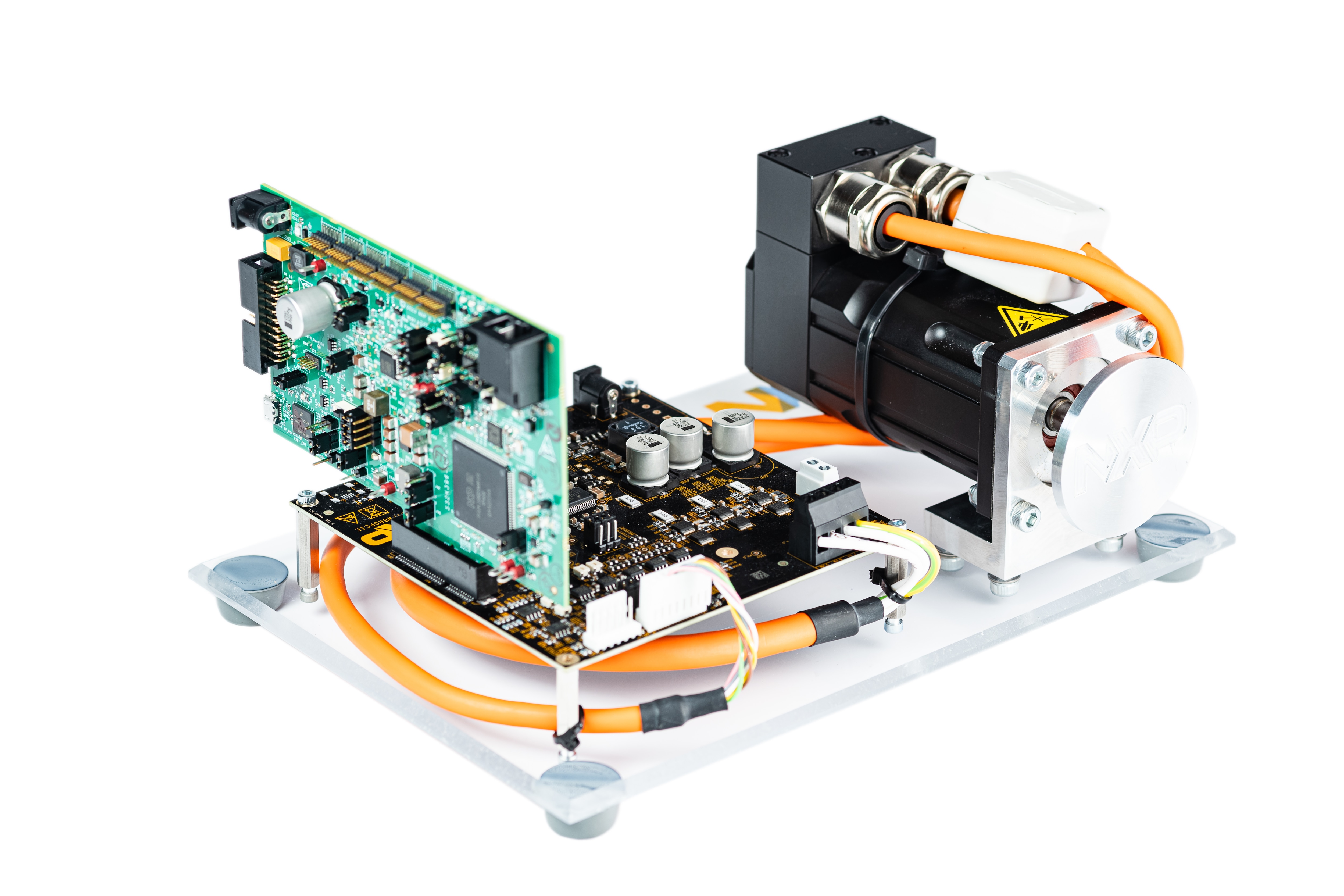
To assemble the controller board to the power stage board, connect the board to the PC with a micro USB cable
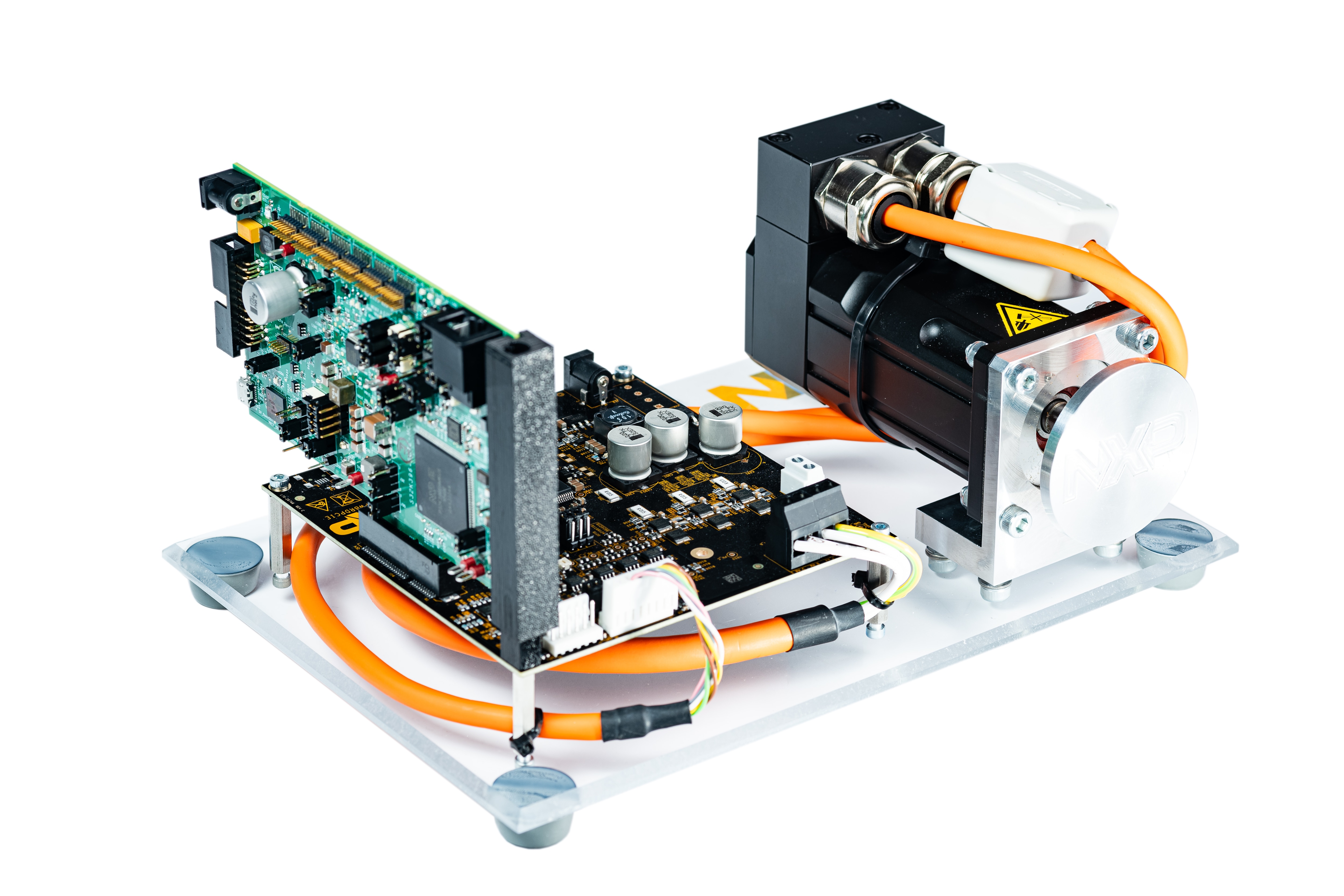
Optionally use the support column for improving mechanical robustness
4. Build, Run
Let's take your MCSTR2AK396 motor control kit for a test drive.
4.1 Select Application and MCU Programing
Select the appropriate PMSM or BLDC motor control application from the installed directory NXP\MC_DevKits\MCSPTR2AK396\sw
.
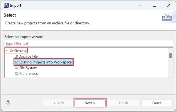
To import the installed application software project in the S32 Design Studio IDE for S32 Platform:
- Launch S32DS for S32 Platform
- Go to File > Import, then select General > Existing Projects into Workspace
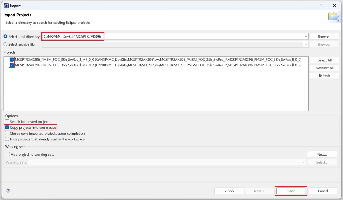
- Navigate to the installed application directory:
NXP\MC_DevKits\MCSPTR2AK396\swand choose appropriate project and click OK. Then, click Finish
4.2 Use Configuration Tool
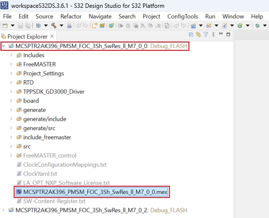
- Unfold the structure of the
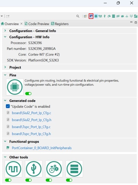
M7_0_0project and double-click on*.mexfile to open the project configuration in S32 Configuration Tool - Ensure that you are configuring the
M7_0_0project, and click Update Code button for generating configuration files. Next, in the S32 Configuration Tool, click the pop down button next to the project name and choose*.mexfile for theM7_0_2project. Click the Update Code accordingly

4.3 Upload Software and Debug
- In S32DS, return back to the C/C++ perspective
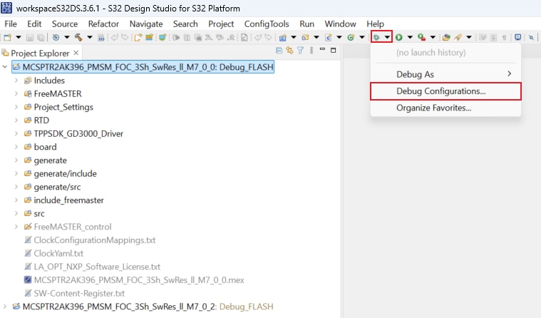
- Use the Debug Configuration menu for uploading software into the MCU
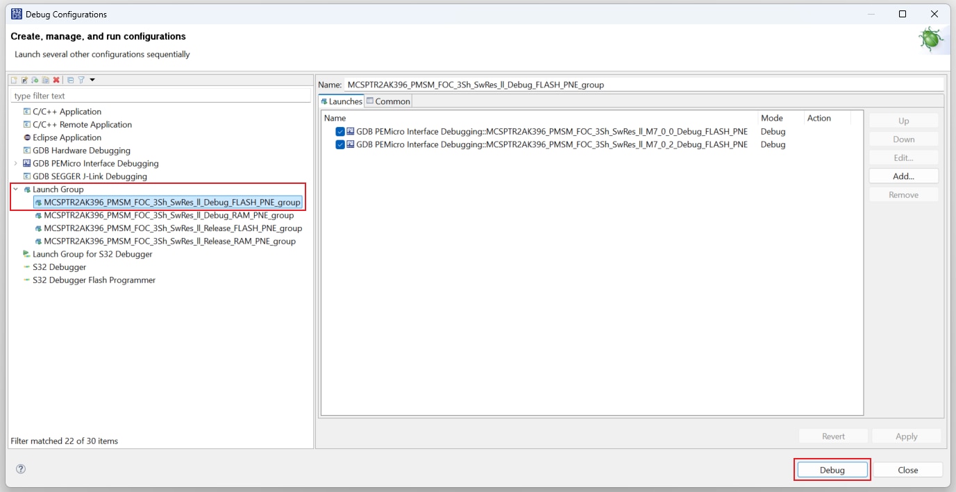
- Next, expand Launch Group and click the first launch configuration. This configuration will upload both the
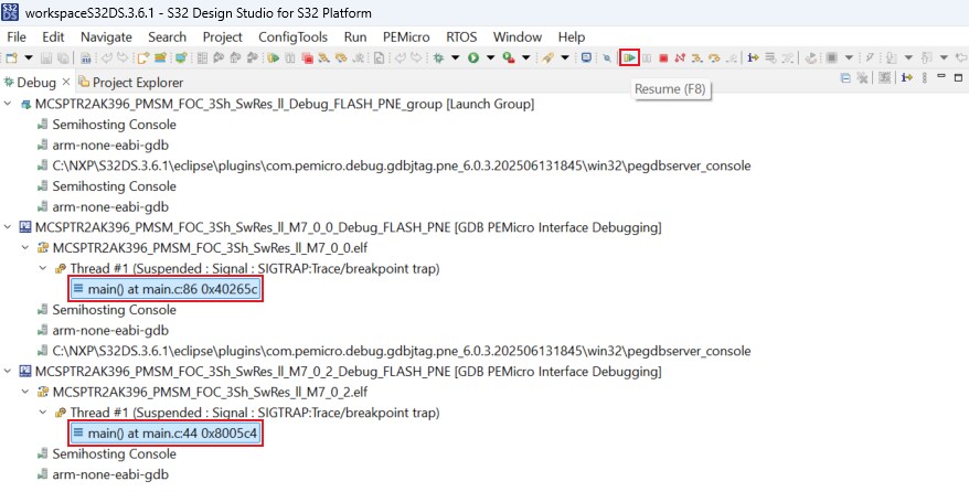
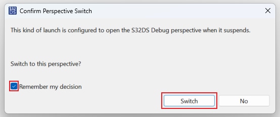
M7_0_0andM7_0_2projects to the MCU. Click Debug for building and uploading software into MCU - The S32DS will switch into debug perspective where you may let the code run by clicking Resume (or press
F8) - Click Disconnect to avoid interference between the S32DS IDE debugger and the FreeMASTER tool
4.4 Set Up the Debugging Tool
Launch the FreeMASTER application.
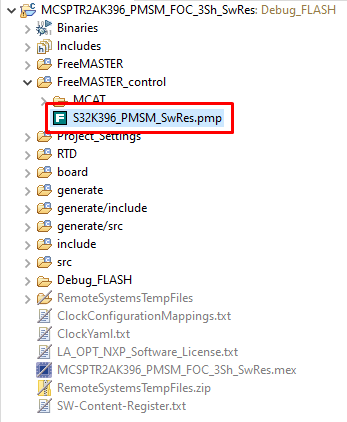
To open the *.pmpx FreeMASTER project
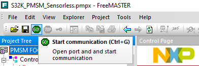
To enable communication, in the FreeMASTER toolbar, click Go (or press Ctrl+G). Successful communication displays in the status bar at the bottom as:
RS-232; port=COMn; speed = 115200
Application Control
Application Setup (Optional Step)
If you run MCSPTR2AK396 sw on a modified or own hardware platform, you may need to edit hardware scales and fault triggers. In the Motor Control Application Tuning (MCAT) Tool switch to the Application Setup page and edit values on the left side.

Once you finish, click Save config to generate a static configuration file. You may check file content at the Output file page.
Now, repeat step from the Upload Software and Debug section to build the project and upload the code into MCU.
Motor Parametrization and Control Loops Autotuning
In a case of motor change, you may benefit from new MCAT 2.0 motor parametrization and control loops autotuning features.
At Motor Parameters page, fill four basic motor parameters that cannot be detected automatically:
- Number of pole pairs
- Nominal Current
- Nominal Speed
- Maximum Speed
Click Update target button and start the motor parameters estimation and automating tuning for control loops. Parameters are automatically updated typically in less than a minute.

For more information about the automatic motor parametrization and control loops autotuning please read AN15061 Application Note in MCSPTR2AK396\doc folder. Default path: c:\NXP\MC_DevKits\MCSPTR2 AK396\doc\ApplicationNotes\AN15061 MCAT 2.0 - Motor Control Application Tuning Tool for PMSM FOC.pdf.
Spin the Motor
Switch, for example, to the Speed Loop page. Under the Speed control tab, configure the required speed and turn on the motor drive.

Select one of the predefined Scopes or Recorders in Project Tree to watch the application variables in real-time. For comfortable run-time debugging you may create or modify any of scopes or recorders.

- Check pending faults
- Start application
- Set Speed
- Stop Application
In case of pending faults, click the CLEAR button at MCAT control tab or alternatively press simultaneously SW2 and SW3 on the board.


Click On/Off on the control bar or press SW2/SW3 on the board to initiate clockwise/counterclockwise spinning of the rotor.
Modify Required Speed field on the control bar or change Speed Required in the Variable Watch window. Alternatively control speed by pressing SW2 or SW3 switches.

Stop the motor by clicking the On/Off button on the MCAT control page, Clear On/Off variable or use the On/Off switch on the 3PHLVPWBRDPCIE board.
Design Resources
Board Information
Chip Documents
Application Documents
Software
-
MCSPTR2AK396 Development Kit Application Software
- Automotive Software Package Manager
- S32K3 Standard Software Package
- S32K3 Reference Software Package
- S32 Design Studio for S32 Platform
- Real-Time Drivers (RTD)
- Automotive Math and Motor Control Library (AMMCLib)
- FreeMASTER Run-Time Debugging Tool
- Motor Control Application Tuning (MCAT) Tool
- Model-Based Design Toolbox (MBDT)
Support
Training
Forums
Connect with other engineers and get expert advice on designing with the MCSPTR2AK396 on one of our community sites.
On this page
- 2.1
Select SW packages from Automotive Software Package Manager
- 2.2
Add GCC Toolchain Version 10.2
- 2.3
Download eTPU SW
- 2.4
Install eTPU SW
- 2.5
Get FreeMASTER Application Tool for Real-Time Debugging
- 2.6
Get Automotive Math and motor Control Library (AMMCLib) Set
- 2.7
Download the Development Kit Application Software