Getting Started with the MCSXTE2BK142
Contents of this document
-
Plug It In
-
Get Software
-
Build, Run
-
Debug
Sign in to save your progress. Don't have an account? Create one.
Purchase your S32K142 BLDC/PMSM Development Board
1. Plug It In
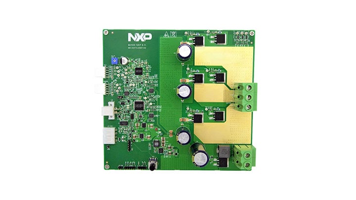
Get Started with the MCSXTE2BK142 for 3-phase Permanent Magnet (BLDC/PMSM) motor
Let's take your MCSXTE2BK142 development board engineered for 3-phase Permanent Magnet (BLDC/PMSM) motor up to 800 W output at 24 V system or up to 400 W at 12 V system for a test drive!
Choose between watching a short setup video or following the step-by-step guide.
1.1 Download the MCSXTE2BK142 Application Software
The Software Package includes the software projects for most typical hardware configurations.
Get MCSXTE2BK142 Application Software1.2 Get your Integrated Development Environment (IDE)
MCSXTE2BK142 performs better when using 32 Design Studio for Arm®-based MCUs
Download S32 Design Studio for Arm1.3 Get the Run-Time Debugging Tool
MCSXTE2BK142 performs better when using the FreeMASTER tool for run-time debugging.
Download FreeMASTER tool2. Get Software
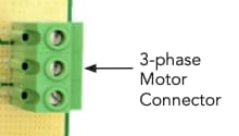
2.1 Connect the Motor
Connect the Permanent Magnet motor using the J11 connector.
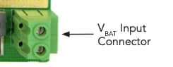
2.2 Plug the Power Supply
Attached the 12/24 V power cable for powering your MCSXTE2BK142 development board, the D13 LED will turn on green.
2.3 Plug the Debugger
Attach your ARM- Cortex compatible JTAG/SWD debugger to the connector J3 or
J4.
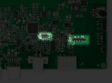
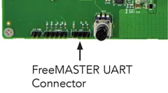
2.4 Plug the Serial Interface
Attach J2 header for connecting the USB to TTL serial interface.
3. Build, Run
3.1 Import the Demo Project Using your IDE
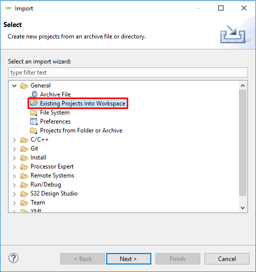
Import the installed application software project in the S32 Design Studio for Arm by launching S32 Design Studio and then click File > Import and then select General > Existing Projects into Workspace.
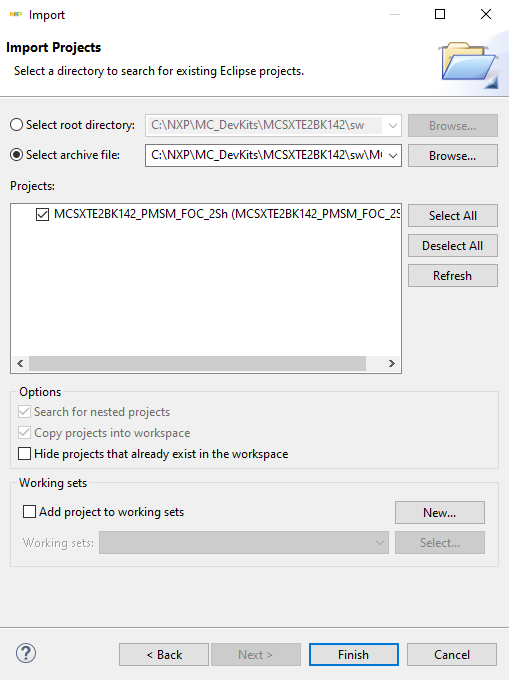
Navigate to the installed application directory: .. MC_DevKits\MCSXTE2BK142\sw
folder, select project and click OK, then
Finish
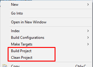
3.2 Optional - Build Project
These steps should not be necessary since they are executed in the next step automatically:
Right click on the imported project and select Clean
Right click on the imported project and select Build
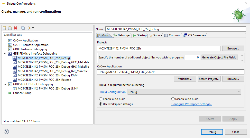
3.3 Debug for Loading Code into the S32K142 MCU
In the S32 Design Studio menu click Run > Debug Configuration and select the predefined debug configuration and click on Debug to start loading built code into MCU.
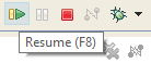
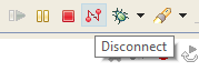
3.4 Let Code Run and Disconnect
Let code run by click on Resume (F8) button. Use the Disconnect button for avoiding interference between S32DS debugger and FreeMASTER tool.
4. Debug
4.1 Start a Debugger Project
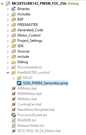
Start the FreeMASTER project for debugging by launching FreeMASTER and then open *.pmp
file from MCSXTE2BK142\FreeMASTER_control folder. File > Open
Project…
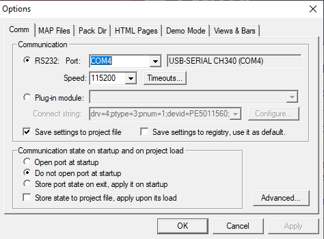
4.2 Create a Connection with the S32K142 MCU
Go to FreeMASTER project options, select the USB to TTL interface serial port at your computer and setup 115kbit per second communication speed.
Click the green GO! button in the FreeMASTER toolbar (or press <CTRL> + <G>) to enable the communication
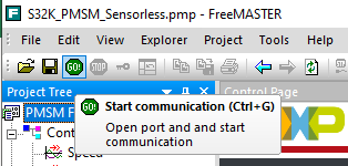
Successful communication is signalized in the status bar at very bottom as:
RS232 UART Communication;COMn; speed = 115200
4.3 Open Application Control Page
In FreeMASTER, go to Control page tab, set required motor rpms and turn on the motor drive.
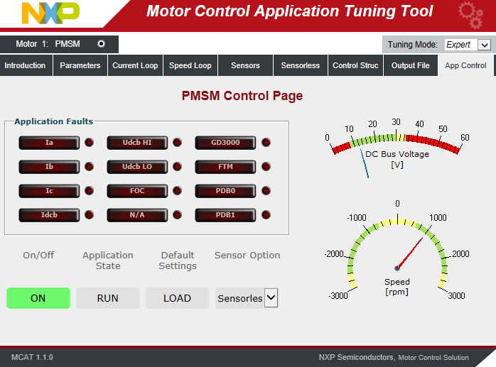
Success! Motor runs.