Getting Started with Alexa Voice Service
Contents of this document
-
Plug It In
-
Get Software
-
Build, Run
-
Learn More
Sign in to save your progress. Don't have an account? Create one.
Purchase your EdgeReady MCU Based Solution for Alexa for IOT
1. Plug It In
1.1 Unboxing
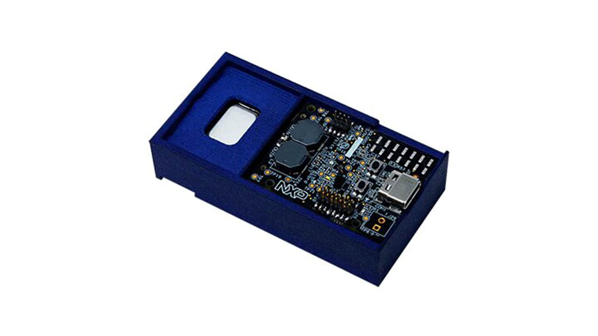
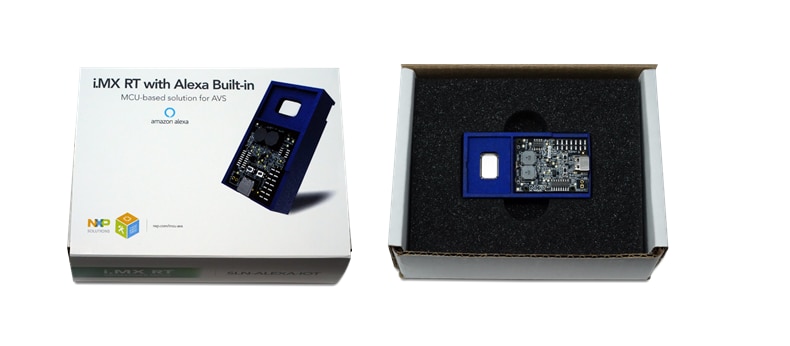
The SLN-ALEXA-IOT Kit arrives in a box as shown below. Inside the box, in addition to the kit, you will find a Quick Start Card, “Let's Get Started!,” and a USB Type-C to dual Type-A cable, as shown in Figure 1. SLN-ALEXA-IOT Kit Contents. The kit is pre-programmed with an audio playback control demo that is ready to run, as soon as it is powered via the USB cable.
1.2 Package and Collateral Content
The owners of the SLN-ALEXA-IOT development kit may have a “Let's Get Started card” in the box. This should have guided you to reach this page.
1.3 Amazon Alexa App and Zero Touch Setup
The SLN-ALEXA-IOT kit needs the Amazon Alexa App used for provisioning and Smart Home control.


For devices that are purchased from Amazon.com, Zero-Touch Setup is enabled for users who already have a Frustration Free Setup enabled device.
1.4 Power On
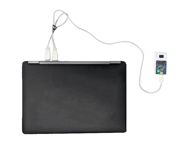
Plug the USB Type-C connector into the SLN-LOCAL-IOT kit and the dual Type-A connectors into your PC. Figure 2 illustrates how to connect the kit with the USB cable.
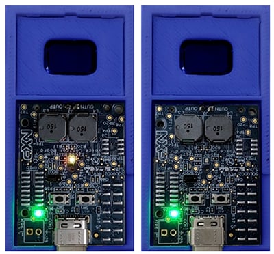
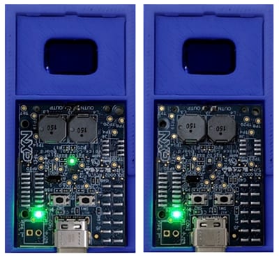
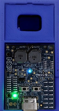
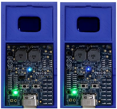
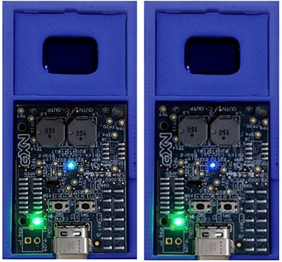
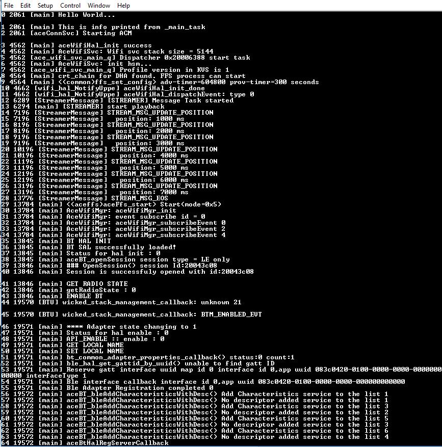
When you power on the kit for the first time, you will see the Status Indicator LED cycling through various color patterns. These are status indicators for the various stages of the boot process as the chip cycles from internal ROM, to bootstrap, to bootloader, to running the application.
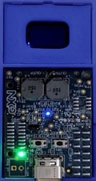
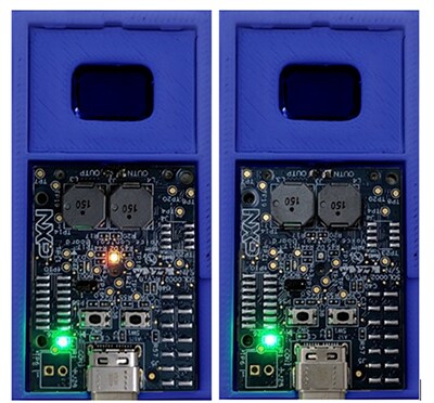
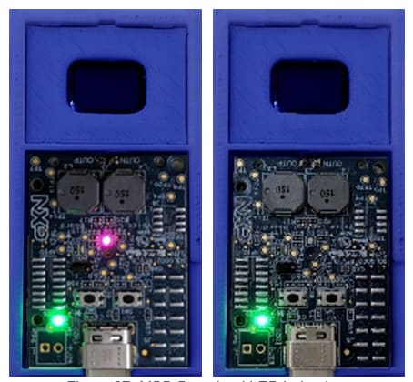
Once the device has been initialized, the Status Indicator LED will be solid blue, as in Figure 3. A sound will be played, instructing the user: “Your device is ready for setup. Make sure Bluetooth permissions on your phone are turned on, then follow the instructions in the Alexa App”.
1.5 User Guided Setup (UGS)
When the device powers up from factory state and there are no conditions for Zero Touch Setup (see paragraph 1.6 ), the SLN-ALEXA-IOT kit will wait for User Guided Setup to be performed via the Amazon Alexa App. The same will happen if Zero Touch Setup was already performed once for the device, as Zero Touch Setup is design to occur only once in the lifetime of a product, no matter if the device was reset to factory settings.
With User Guided Setup the mobile phone, running the Amazon Alexa App will play the role of FFS provisioner.
To perform User Guided Setup, ensure the Amazon Alexa App is installed on your mobile device. Also make sure that Bluetooth and Location permissions for the app are enabled on your phone.
Open the Alexa App and log into your Amazon Alexa account. Alexa App should detect that a nearby device is waiting to be onboarded with UGS. A window should pop-up, prompting the user to start the set-up process.
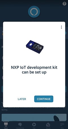
If the user presses on LATER, or if, for some reason, the pop-up page does not appear in Alexa App, there is an alternative way for starting the UGS process.
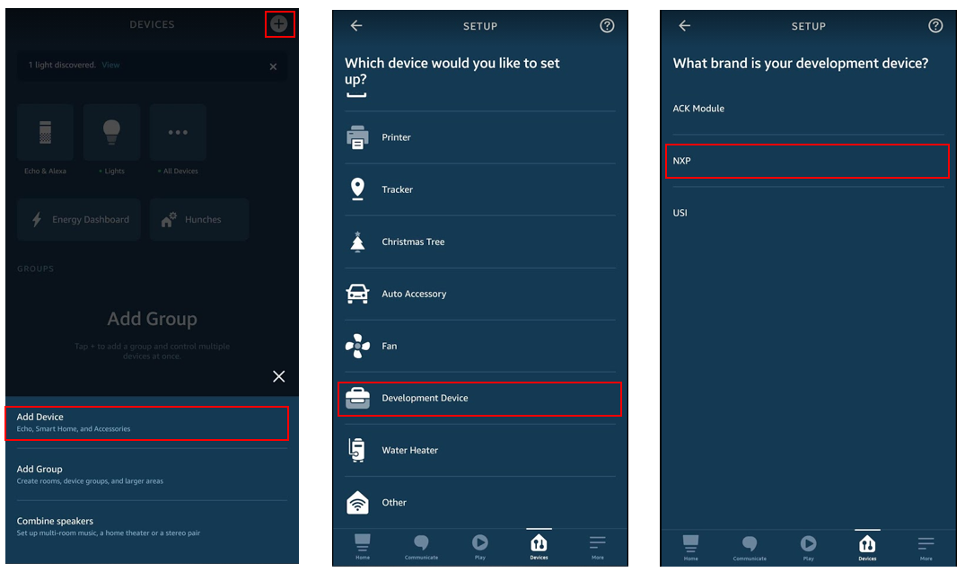
Select the Devices tab, then select the plus sign + . In the popped-up window, select Add Device. Select Development Device from the list shown. Select NXP for What brand is your development device, then click next.
After the FFS provisioner connects to the device, Status Indicator LED will start to blink orange.
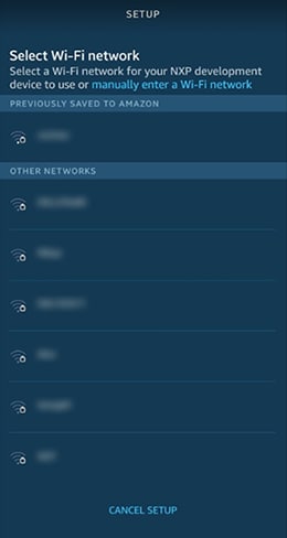
The FFS provisioner will now ask the device to scan the environment and send the list of Wi-Fi networks it detects. This list will be displayed in the Alexa App and the user will have to choose the network to which the device should connect.
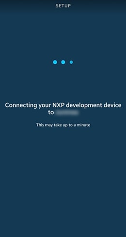
After the Wi-Fi network is selected, the screen will display the message” Connect your NXP Development device to… ” while the Wi-Fi provisioning and communication with the FFS servers is taking place.
The Status Indicator LED blinking orange will continue until the FFS registration completes. When this happens, a sound will be played, saying: “Your Alexa device is ready”. A reboot will be issued after this.
The Status Indicator LED will signal again the booting state. The device will then try to connect to the Wi-Fi network provisioned previously. The Status Indicator LED will blink yellow at 500ms cycles. After connecting to the Wi-Fi, the yellow blinking will be faster, at 250 ms cycles.
Next the device will start to connect to AWS IoT servers. The LED will start blinking green every 500ms until the device has successfully connected. When connected, the green blinking will be faster, at 250 ms.
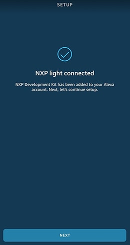
Note that the screen in Figure 7 will continue to be shown until the device connects to AWS IoT. Alexa App will consider that the onboarding process was completed only after the device will try the first connect post UGS. When this happens, the screen shown in Figure 10 will appear. The message in Alexa App is “NXP light connected” because the device implements “Light” Smart Home capabilities.
After the “chime” sound will be played, the user can start interacting with Alexa, as described in section 1.7.
1.6 Zero Touch Setup (ZTS)
In ZTS scenarios, after powering up, the device will be discovered by an existing ZTS provisioner - a list of WSS over BLE provisioners can be found here - and will automatically be onboarded to the user account.
As the process proceeds, the Status Indicator LED states will be the same as the ones described for User Guided Setup. There will be log messages sent to the SLN-ALEXA-IOT console over its virtual COM port followed by the Alexa “chime” sound. The SLN-ALEXA-IOT kit will then respond to Alexa commands.
The entire ZTS process, from power up to Alexa “chime” should last around 72 seconds.
The prerequisites to have the ZTS happening are:
- Have the SLN-ALEXA-IOT development kit from Amazon.com
- SLN-ALEXA-IOT has not been purchased or received as a gift
- Have a “provisioner device” already installed - i.e. Echo Dot (3rd Gen)- in the targeted Wi-Fi network
- Have the Credentials for the targeted Wi-Fi Network available in the Amazon Wi-Fi Locker
- Have an Alexa Skill linked to the Amazon account
- Power up SLN-ALEXA-IOT within the BLE range of the provisioner device
Please note: this feature was designed by amazon in such a way that it will only be triggered once in the lifetime of a device, no matter if the device was reset to factory settings.
1.7 Interacting with Alexa
One of the most common interactions users can have with SLN-ALEXA-IOT is asking a question. A simple request, for example “Alexa, what's the weather?” has various states from processing and responding.
The first indication that the device is listening is when the “Alexa” wake word is uttered. When SLN-ALEXA-IOT detects the wake word, a cyan light will be shown (Status Indicator LED) and will start to listen and send microphone data to AVS via AWS IoT.
After the device has finished sending microphone captures to AVS via AWS IoT, the device will stop listening and go into thinking state. This state indicates that the AVS is processing the request and is trying to give the best response. While in this state, the devices Status Indicator LED will blink cyan and blue every 200 ms.
After the device has finished thinking, it will start to respond. Before audio is outputted from the speaker, the Status Indicator LED will go into speaking state, which is shown by blinking cyan and blue every 500 ms.
While the Status Indicator LED is blinking cyan, the response from Alexa will start playing out of the speaker. The response should be indicating the weather conditions based on the location of your Alexa consumer account. Once this has completed, the Status Indicator LED will stop blinking and turn off to indicate it is now in an idle state waiting for the Alexa wake word.
2. Get Software
2.1 Jump Start Your Design with the MCUXpresso SDK
The MCUXpresso SDK is complimentary and includes full source code under a permissive license for all hardware abstraction and peripheral driver software.
Click below to download a pre-configured SDK release for the SLN-ALEXA-IOT Development Kit

2.2 Install Your Toolchain
NXP offers a complimentary toolchain called MCUXpresso IDE.

2.3 PC Configuration
Many of the example applications output data over the MCU UART, so you'll want to make sure that the driver for the board's virtual COM port is installed. On Windows 10 systems the driver is automatically installed after the board is plugged into the PC. For older Windows systems, one can use the driver linked below.
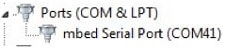
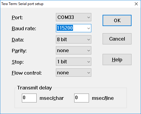
With the serial port driver installed, run your favorite terminal application to view the serial output from the MCU's UART. Configure the terminal to 115200 baud rate, 8 data bits, no parity and 1 stop bit. To determine the port number of the SLN-ALEXA-IOT virtual COM port, open the device manager and look under the "Ports" group.
Not sure how to use a terminal application? Try one of these tutorials: Tera Term Tutorial, PuTTY Tutorial.
3. Build, Run
3.1 Explore the MCUXpresso SDK Example Code
The MCUXpresso SDK comes with a long list of example application code. To see what's available, browse to the SDK boards folder of your SDK installation and select your board, the SLN-ALEXA-IOT (/boards/sln-alexa-iot).
To learn more about specific example code, open the readme.txt file in an example's directory.
3.2 Build, Run and Debug MCUXpresso SDK Examples
If one or more of the demo applications or driver examples sounds interesting, you're probably wanting to know how you can build and debug yourself. The Getting Started with MCUXpresso SDK guide provides easy, step-by-step instructions on how to configure, build and debug demos for all toolchains supported by the SDK.
Use the following guide to learn how to open, build and debug an example application using MCUXpresso IDE. Use MCUXpresso IDE.
4. Learn More
4.1 Updating Locale Settings
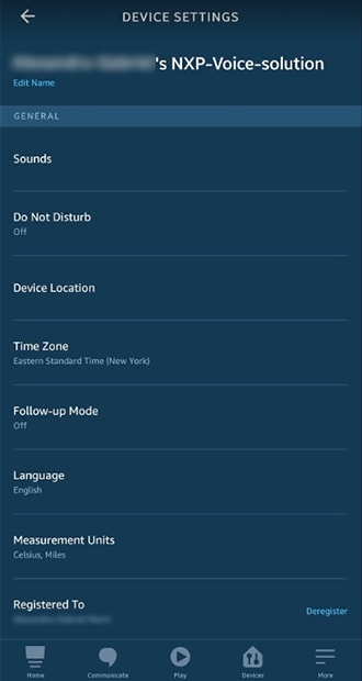
One can change the device locale from Alexa App settings. For this, it will be needed to open the devices list, then click on the device for which it is wanted to update the locale settings. This will open the “Device Settings” page, as shown in the next image.
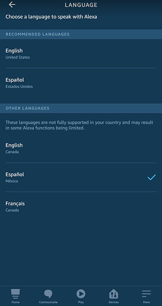
Next, clicking on “Language” will open a screen with the languages that the device reported as being supported. We are demonstrating here the locale change to “es-MX”.
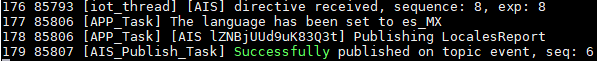
Selecting a new language in the screen above will trigger a directive being sent to the device, which will perform a wake word model re-initialization. Some logs will be printed in the console, as shown in the next image.
Now the user can utter the wake word and ask Alexa something using the language that was set in Alexa App for the device. For example, asking “Alexa, como estas?” will make the service to reply in Spanish.
For more details regarding the locales support, please check SLN-ALEXA-IOT-DG.
4.2 Smart Home
The firmware on the device is using Smart Home APIs. Moreover, it is emulating a light switch. This means the user can control it either from Alexa App or through voice commands as it would be a light switch smart device. Please note that the Smart Home callbacks are not controlling any actual hardware, like an LED for example. They were implemented to simply log something to the console every time a Smart Home directive is received from the cloud.
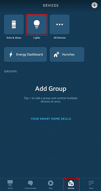
In order to control SLN-ALEXA-IOT's Smart Home capabilities from Alexa App, in “Devices” screen, select Lights, as shown below.
The SLN-ALEXA-IOT device should be listed with the name “NXP Development Kit”. Click on it to control it using the controls shown in the next images.
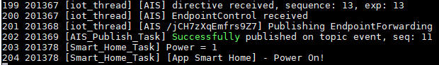
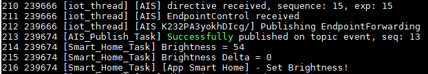
When “Power” is turned on, a log will be printed to the console, like the one showed below. When the brightness will be modified, another log will be printed to the console.
Alternatively, one could use voice commands to achieve the same results. “Alexa, turn off NXP Development Kit” or “Alexa, set NXP Development Kit's brightness to 80%” will modify the Smart Home Device's state accordingly. This will also update the state in the Alexa App.
For more details regarding Smart Home endpoints, please check SLN-ALEXA-IOT-DG.
4.3 Mass Storage Device (MSD) Update
The MSD feature allows the device to be updated without the Segger tool and instead, via USB. Only the
“ais_ffs_demo” can be updated while the bootloader and bootstrap remain the same. If the bootstrap and bootloader need updating, this will have to be done via Segger or the Updater flow.
The MSD feature by default bypasses signature verification to allow an easier development flow as signing images can be a process not suitable for quick debugging and validation.
WARNING
Please note: bypassing image verification is a security hole and it is the responsibility of the product maker to remove the violation.
To put the device into MSD mode, hold down switch 2 (SW2) and power cycle the board until the purple Status Indicator LED blinks on and off three second cycles.
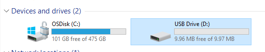
After observing the Status Indicator LED behavior, navigate to “My Computer” and confirm that the SLN-ALEXA-IOT kit has mounted as a Mass Storage Device.
Take the compiled “ais_ffs_demo” binary and drag the file into the MSD. This will start the download process and write the binary to flash.
After the image has been programmed into flash, the image that has been loaded will begin to execute. Validate this by checking the version of the image compiled, matches the version in the console by typing “version”.
If the image is compiled to run in the wrong application bank, an error will occur. The developer will be required to recompile the application to the bank the device is not running from.
WARNING
Please note: this requires an ais_ffs_demo binary that has been compiled to run in the opposite bank the current application is running in.
4.4 Connect a Serial Terminal
Connect a serial terminal application to the USB serial device interface that enumerates (115200-8-N-1). Next figure is a snapshot of serial terminal setup.
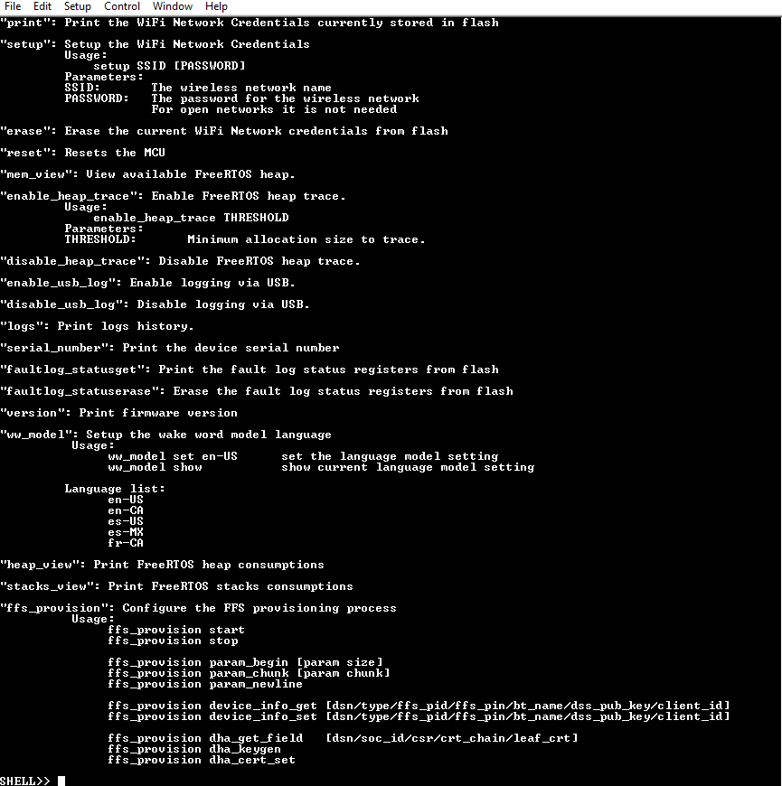
Press Enter on the keyboard and you will see the SHELL>> prompt. Type help to show the available commands. Figure below shows the available commands, with a description of each.
To obtain the logs of the SLN-ALEXA-IOT kit, type “logs” in the serial console.
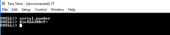
4.5 Obtain the Serial Number via Serial Terminal
Some situations require access to the serial number for onboarding or other scenarios. To obtain this, in the serial console, type “serial_number” which will output the serial number of the SLN-ALEXA-IOT kit.
4.6 Migrate to your own AWS IoT
The SLN-ALEXA-IOT kit connects to an NXP Semiconductor AWS Server by default, to show how consumers would use Out-Of-Box. To migrate it to a developer's account, navigate to the SLN-ALEXA-IOT-MG guide, which details the process.
Tera Term Tutorial
Tera Term Tutorial
Tera Term is a very popular open source terminal emulation application. This program can be used to display information sent from your NXP development platform's virtual serial port.
- Download Tera Term from SourceForge. After the download, run the installer and then return to this webpage to continue
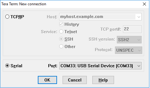
- Launch Tera Term. The first time it launches, it will show you the following dialog. Select the serial option. Assuming your board is plugged in, there should be a COM port automatically populated in the list
- Configure the serial port settings (using the COM port number identified earlier) to 115200 baud rate, 8 data bits, no parity and 1 stop bit. To do this, go to Setup -> Serial Port and change the settings
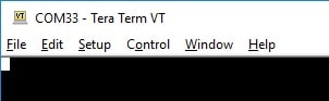
- Verify that the connection is open. If connected, Tera Term will show something like below in it's title bar
PuTTY Tutorial
PuTTY Tutorial
PuTTY is a popular terminal emulation application. This program can be used to display information sent from your NXP development platform's virtual serial port.
- Download PuTTY using the button below. After the download, run the installer and then return to this webpage to continue
- Launch PuTTY by either double clicking on the *.exe file you downloaded or from the Start menu, depending on the type of download you selected
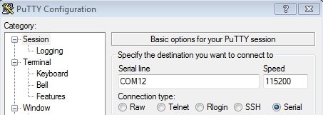
- Configure In the window that launches, select the Serial radio button and enter the COM port number that you determined earlier. Also enter the baud rate, in this case 115200
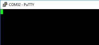
- Click Open to open the serial connection. Assuming the board is connected and you entered the correct COM port, the terminal window will open. If the configuration is not correct, PuTTY will alert you.
- You're ready to go
Use MCUXpresso IDE
Use MCUXpresso IDE
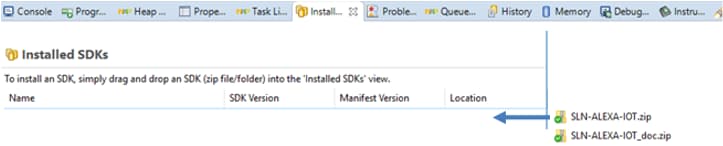
Before building the SLN-ALEXA-IOT SDK example projects, the target SDK needs to be imported into MCUXpresso IDE by drag and dropping the target SDK archive into the “Installed SDKs” window from MCUXpresso IDE. Next figure shows where to drag and drop.
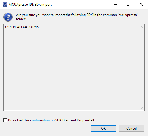
the SDK and the one below shows the pop-up windows, which asks for confirmation (press OK).
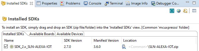
Once the package has been imported, it will be displayed in the list of installed SDKs. The next image shows the installed SDKs in the MCUXpresso.
Import SLN-ALEXA-IOT Projects
The SLN-ALEXA-IOT SDK allows you to import existing application examples as a development starting point. Some applications are intended to handle most of the voice aspects of the functionality allowing developers to focus on the product innovation.
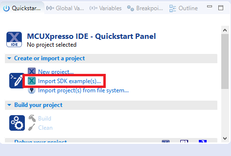
The following steps show how to import SLN-ALEXA-IOT projects into MCUXpresso IDE. From the Quickstart Panel, select Import SDK examples(s) as in the figure below.
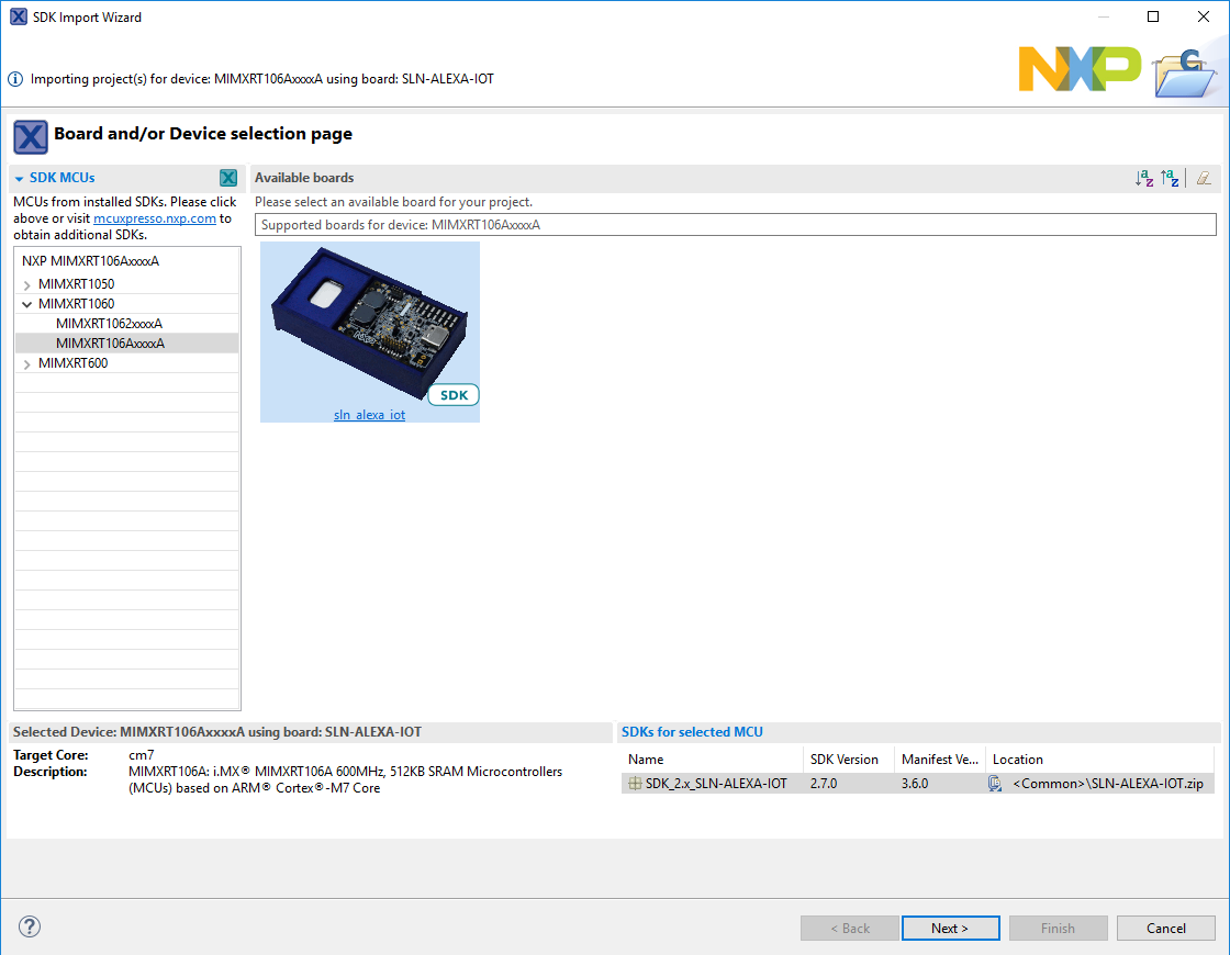
A list of all the installed board SDK's will be shown that have examples that can be imported from. Select the “sln_alexa_iot” image and then proceed with selecting the next button as in the following picture.
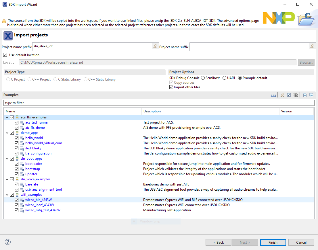
The import wizard will then display all the applications that are available to import. Ensure the SDK Debug Console isn't changed from its default position. The next image exemplifies importing of all the available projects.
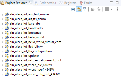
Once the projects have been successfully imported, they will be listed in the project explorer ready to build and run. This document is going to focus on the ais_ffs_demo and bootloader and bootstrap for building and debugging.
Building the Bootstrap, Bootloader and AIS FFS Demo
The bootstrap project is the first application that is booted. To summarize, the bootstrap is a minimal FreeRTOS application that is responsible for image verification. Moreover, if i.MX RT HAB (High Assurance Boot) is enabled on the chip, bootstrap is the signed trusted firmware. It also manages the eXIP (Encrypted Execution in Place) context. This firmware is designed to avoid any update as a corruption of this image will result in an unbootable image and bricked device.
The bootloader project is a second stage bootloader that manages jumping into the ais_ffs_demo application. This application can be used for any additional bootloader functionality needed for the product. This bootloader is also responsible for Mass Storage Device drag and drop and OTA Image updating. The bootloader is also responsible for validating OTA images via signature verification and creating additional crypto context in the case of eXIP being enabled.
The ais_ffs_demo is an application that is fully responsible for onboarding via FFS (based on ACS layer), AWS IoT connection and Alexa interaction. This is the main application that runs the full Alexa application.
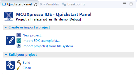
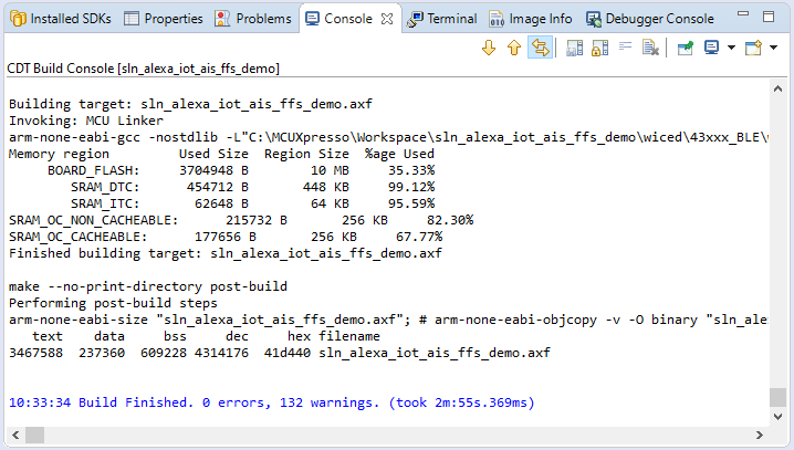
From the Quickstart Panel, select the option Build to start the compilation and linking of the application for sln_alexa_iot_bootstrap, sln_alexa_iot_bootloader and sln_alexa_iot_ais_ffs_demo. The next image shows that sln_alexa_iot_ais_ffs_demo project is selected and will start compile after the “Build” button is pressed.
Wait for the console to finish the build. This will take a few minutes. The result of a successful compilation of the sln_alexa_iot_ais_ffs_demo project can be seen below.
Turning Off Image Verification
As mentioned in previous sections, the SLN-ALEXA-IOT kit has image verification turned on by default. This has the security feature of only booting images that are signed with the Certificate Authority that is associated with the application certificate and Certificate Authority certificate programed in flash. This has the added consequence of not being able to program an image into flash and boot successfully.
For development, it might be considered to turn this feature off to avoid having to sign images or in the case of using NXPs security material, being unable to sign images. To do this, there are several modifications that need to be made which are described in the following sections. Image verification must be turned off for both the Bootstrap and the Bootloader components.
Turning Off Bootstrap Image Verification
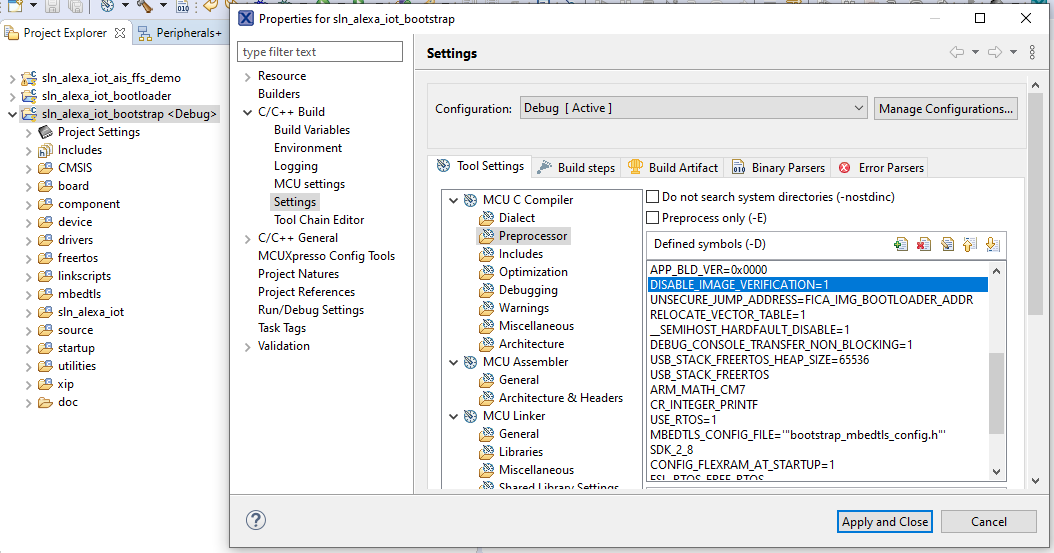
To turn off the image verification within the bootstrap, code modifications are required. Within the MCUXpresso bootstrap project, right click on the root project and navigate to:
- Properties → C/C++ Build → Settings → Preprocessor.
Inside the Preprocessor section, change the MACRO “DISABLE_IMAGE_VERIFICATION” to “1” and press “Apply and Close”.
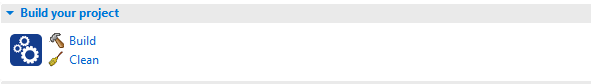
After that change, from the Quickstart Panel, select the option Build to start the compilation and linking of the bootstrap.
Turning Off Bootloader Image Verification
To turn off the image verification within the bootloader, code modifications are required. Within the MCUXpresso bootloader project, right click on the root project and navigate to:
- Properties → C/C++ Build → Settings → Preprocessor
Inside the Preprocessor section, change the MACRO “DISABLE_IMAGE_VERIFICATION” to “1” and press “Apply and Close”.
After that change, from the Quickstart Panel, select the option Build to start the compilation and linking of the bootloader.
From the Quickstart Panel, select the option Build to start the compilation and linking of the application for, sln_alexa_iot_bootstrap, sln_alexa_iot_bootloader<network support> and sln_alexa_iot_ais_demo<network support>.
Wait for the console to finish the build process which will take a very short time due to the small size.
Programming Firmware Images
With the bootstrap, bootloader and ais_ffs_demo all compiled, it's now time to program them into the flash. This section assumes that you have turned off image verification as described in the “Turning Off Image Verification” section.
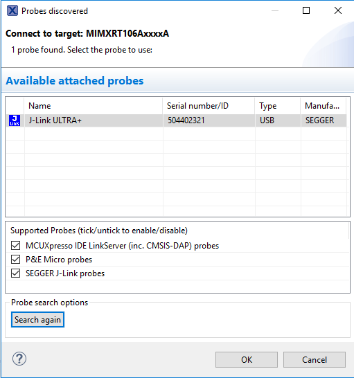
The following steps are to be done for: bootstrap, bootloader and ais_ffs_demo. Select the Debug option and ensure the debug probe is attached. This will start the process of loading the binary into the flash.
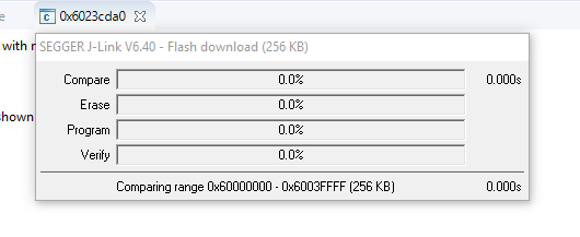
Select the J-Link probe that is connected to the board and press OK.
This will launch the flashing tool and proceed to load the image into the flash as shown below. When this is complete, you can proceed to the debug section.
On this page
- 1.1
Unboxing
- 1.2
Package and Collateral Content
- 1.3
Amazon Alexa App and Zero Touch Setup
- 1.4
Power On
- 1.5
User Guided Setup (UGS)
- 1.6
Zero Touch Setup (ZTS)
- 1.7
Interacting with Alexa