Getting Started with i.MX 6 SoloX SABRE
Contents of this document
-
Out of the Box
-
Linux/Android
-
FreeRTOS
-
Exploration
Sign in to save your progress. Don't have an account? Create one.
Purchase your i.MX 6SX SABRE Board
1. Out of the Box
This page will help guide you through learning about the NXP Linux® OS BSP and SABRE development tool for i.MX 6SoloX.
Development Kit Contains:
- i.MX 6SoloX SABRE board for smart devices
- USB cable (micro-B to standard-A)
- 5 V/5 A universal power supply
- Quick Start Guide
- 8 GB SD Card with bootable operating system demonstration image
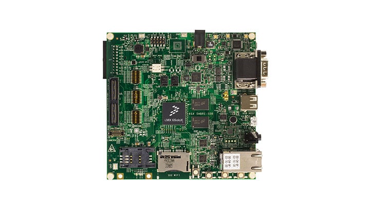
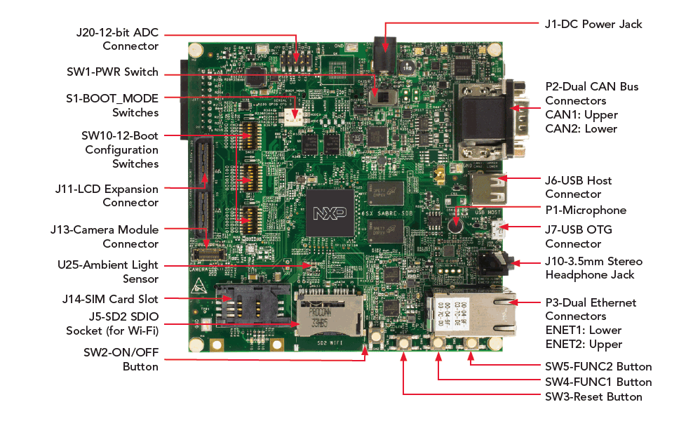
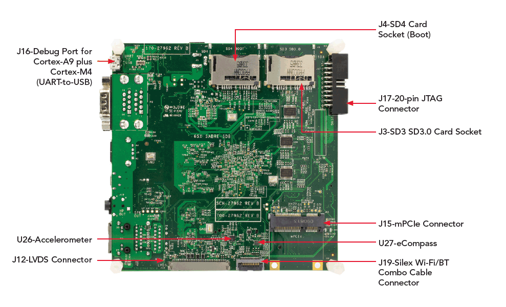
1.1 Get Familiar with the Board
1.2 Insert the SD Card (SD4)
The kit comes with an SD card with a prebuilt NXP Linux® BSP image. Without modifying the system, booting from the image will provide a default system with certain features for building other applications on top of Linux®.
To understand more about NXP Linux®/Android™/FreeRTOS BSP image, please continue reading next sections.
1.3 Connect USB Debug Cable
Connect the micro-B end of the supplied USB cable into Debug UART port J16.
Connect the other end of the cable to a host computer.
Terminal window configuration: 115200 baud, 8 data bits, 1 stop bit, no parity
On Linux® host machine, run the following command to determine the port number:
$ ls /dev/ttyUSB*
Use the following command to install serial communication program (minicom as an example):
$ sudo apt-get install minicom
On Windows to determine the port number of the i.MX board virtual COM port, open the device manager and look under the "Ports" group.
Two UART connections will appear on the PC for debugging Cortex-A9 and Cortex-M4.
If needed, the serial-to-USB drivers can be found at FTDrivers.htm .
Not sure how to use a terminal application? Try one of these tutorials: Tera Term Terminal, PuTTY Terminal.
1.4 Connect LVDS Panel
Connect the LVDS panel with capacitive touch (MCIMX-LVDS1) to the LVDS connector J12.
1.5 Connect Ethernet Cable (Optional)
Connect an Ethernet cable to the lower port of the Ethernet jack P3.
1.6 Connect Power Supply
Connect the 5 V power supply cable to the 5 V DC power jack J1.
When powered on by flipping SW1 Power switch to ON, the processor starts executing code from on-chip ROM.
With
default Boot Switch setup, this code reads the fuses to find out which media to search for a bootable
image.
Then it will find the SD card and begin U-Boot execution automatically.
Information will be printed in the serial console. If you don’t stop the U-Boot process, it will boot the Linux® kernel.
The Linux® penguin images will initially appear in the upper left corner of the display. When the boot process is complete, the Yocto Project® operating system will be displayed on the LVDS panel.
1.7 Congratulations Your Linux® is booted
Once Linux® is booted, you can log in with user name root and no password.
To jump in U-Boot, press any key before the value of the U-Boot environment variable, "bootdelay", decreases and before it times out (default 3 seconds). If you stop the U-Boot process, you can run the following command to boot Linux® again:
U-Boot >boot2. Linux/Android
Choose a Development Path:
2.1 i.MX Linux® Board Support Package

i.MX Linux® Board Support Package
- Long-Term Support Kernel Release
- U-Boot
- Yocto Build Tools
The i.MX Linux® Board Support Package (BSP) is a collection of binary files, source code, and support files that can be used to create a U-Boot boot loader, a Linux® kernel image, and a root file system for i.MX development systems. Current releases of BSP and source code can be found on imx6tools.
Overview
Before the Linux® OS kernel can boot on an i.MX board, the Linux® image needs to be copied to a boot device and the boot switches need to be set to boot that device.
To bring up the board and run Linux®, four elements are needed:
- Boot loader (U-Boot)
- Linux® kernel image (zImage)
- A device tree file (.dtb) for the board being used
- A root file system (rootfs) for the particular Linux® image
Prepare a Linux® BSP Image
Prebuilt Image
The release contains a prebuilt SD card image that is built specifically for the i.MX 6Quad Sabre-SD board. The SD card image is a file that is typically named
The prebuilt NXP Linux® Binary Demo Image provides a typical system and basic set of features for using and evaluating the processor. Without modifying the system, the users can evaluate hardware interfaces, test SoC features, and run user space applications.
Self-built Image
With the source code and documentation, the users also can customize the Linux® image built for your own device, i.e. add or remove system components.
The Yocto Project is the framework of choice with NXP professional support to build the images that are used for booting a Linux® kernel, although other methods can be used.
For more details, see NXP Yocto Project User’s Guide.
Download Linux® BSP Image
There are various ways to download the Linux® BSP image for different boards, boot devices, and results desired.
For Getting-Started, we only list the few methods to transfer the BSP image to SD card. Experienced Linux® developer can explore other options.
The.Sdcard image (either from a prebuilt or self-built BSP image) is an SD card image that can be flashed directly. This is the simplest way to load everything needed onto the card with one command.
When more flexibility is desired, an SD card can be loaded with the individual components (boot loader, kernel, dtb file, and rootfs file) one-by-one or the.Sdcard image can be loaded and the individual parts can be overwritten with the specific components.
Copying the full SD card image
An SD/MMC card reader is required to transfer the boot loader and kernel images to initialize the partition table and copy the root file system.
Linux® host:
The Linux® kernel running on the Linux® host assigns a device node to the SD/MMC card reader.
To identify the device node assigned to the SD/MMC card, carry out the following command in the host computer:
WARNING: The instructions below will permanently delete existing content on the SD card and are dangerous to your PC if run incorrectly. If you have question or would like further details, please consult the i.MX Linux® User's Guide.
$ cat /proc/partitions
Carry out the following command to copy the SD card image to the SD/MMC card. Change sdx below to match the one used by the SD card.
$ sudo dd if=
Where
Make sure that the device node is correct for the SD/MMC card. Otherwise, it may damage your operating system or data on the hard disk of your computer.
To set up the partition manually, please read 4.3.3 in i.MX Linux® User's Guide.
To load individual component separately when the full SD card image is not used, please read 4.3.4-3.4.6 in i.MX Linux® User's Guide
Using U-Boot
The U-Boot boot loader is able to download images over Ethernet to RAM and then writes to an SD card. For this operation. Network communications need to be configured.
For instructions about how to download U-Boot to an MMC/SD card that is not the one used to boot from, please refer to section 4.4.1
Images can be downloaded to other boot media (memory storage device) using U-Boot. To use other memory device, please refer to sections under 4.4.1
Using Manufacturing Tool
The Manufacturing Tool, named MfgTool, is a tool that runs on a Windows OS host and is used to download images to different devices on an i.MX board. The tar.gz file can be found with the prebuilt Linux® BSP image.
2.4 Boot Switch Setup
The boot modes of the i.MX boards are controlled by the boot configuration DIP switches on the board.
The following table shows the DIP switch settings for booting from the SD card slot labeled SD2 and J500 on the i.MX 6 SABRE-SD boards. The SD2 card slot is located beside the LVDS1 connection on the back of the board.
Booting from SD2 (J500) on i.MX 6 SABRE-SD
| Switch | D1 | D2 | D3 | D4 | D5 | D6 | D7 | D8 |
|---|---|---|---|---|---|---|---|---|
| SW6 | On | OFF | OFF | OFF | OFF | OFF | ON | OFF |
For boot switch setup to boot from other device (SD3 and SATA), please refer to 4.5 in i.MX Linux® User Guide.
2.2 i.MX Android™ Board Support Package

- Android™ Compatibility Test Suite (CTS) compatible Release
- Extended Multimedia Features
This section walks through the booting process of the i.MX 6QuadPlus SABRE board with the Android™ system image and briefly introduce how to build the software components that create your own system image. For more information about building the Android™ platform, see Android .
Current releases of Demo Images and source code can be found on imx6tools .
Overview
The storage devices on the development system (MMC/SD or NAND) must be programmed with the U-Boot boot loader. The i.MX 6 series boot process determines what storage device to access based on the switch settings. When the boot loader is loaded and begins execution, the U-Boot environment space is then read to determine how to proceed with the boot process.
The images from the prebuilt release package or created from source code contain:
- U-Boot image: u-boot.imx
- boot image: boot.img
- Android™ system root image: system.img
- Recovery root image: recovery.img
Prepare an Android™ BSP Image
The images needed to create an Android™ system can either be obtained from the release package or be built from source.
Prebuilt Image
The prebuilt NXP Android™ demo image will provide a default system with certain features for purpose of evaluation. Without modifying the system, the users can perform some basic operations, and interact wit the system to test hardware interfaces and develop software application in the user space.
The latest prebuilt demo files can be found in Android™ section at imx6tools .
Self-built Image
Preparation
To build the Android™ source files, use a computer running Linux® OS. Ubuntu 14.04 (64-bit) versions are the ones we have tested the most for Android™ Marshmallow 6.0 build.
After installing the computer running Linux® OS, check whether you have all the necessary packages installed for an Android™ build. See "Setting up your machine" on the Android™ website .
In addition to the packages requested on the Android™ website, please refer to Android™ User Guide to install the additional packages.
Get the source code
Get the Android™ source code from Google repo.
Get the kernel source code and U-Boot from Freescale open source Git.
Patch
Apply all the i.MX Android™ patches. For details, please refer to Android™ User Guide.
Build
The build configuration command lunch can be issued with an argument
Here is an example to build the Android™ image with user type for the i.MX 6Quadplus SABRE Board:
$ cd ~/myandroid
$ source build/envsetup.sh
$ lunch sabresd_6dq-user
$ make 2>&1 | tee build-log.txt
When the make command is complete, the build-log.txt file contains the execution output. Check for any errors.
To create Android™ platform over-the-air, OTA, and package, the following make target is specified:
$ make otapackage
Download Android™ BSP Image
Download Image using Linux® Utility
The Linux® utility "dd" on the computer running Linux® OS can be used to download the images into the SD card.
Before downloading, ensure that your partitions are created as described in Storage partitions.
Download Image using Manufacturing Tool
The Manufacturing Tool, named MfgTool, is a tool that runs on a Windows OS host and is used to download images to target devices on an i.MX board. The tar.gz file can be downloaded in Manufacturing Tools section at imx6tools .
Boot Switch Setupe
The boot modes of the i.MX boards are controlled by the boot configuration switches on the board.
The following table lists the boot switch settings for different boot methods:
| eMMC 4-bit (MMC2) boot | (SW6) 11100110 (from 1-8 bit) |
| eMMC 8-bit (MMC2) boot | (SW6) 11010110 (from 1-8 bit) |
| SD boot | (SW6) 01000010 (from 1-8 bit) |
For boot switch setup to boot from NAND/TFTP/NFS, please refer to 6.2-6.3 in i.MX Android™ User's Guide.
To boot with HDMI® displays, please refer to section 3.4 for more instructions.
3. FreeRTOS
The FreeRTOS BSP for i.MX 6SoloX is a suite of robust peripheral drivers, FreeRTOS support, and multicore communication mechanism designed to simplify and accelerate application development on i.MX 6SoloX Processor.
Current releases of BSP and source code can be found under FreeRTOS section on imx6tools.
3.1 Overview
The FreeRTOS BSP for i.MX 6SoloX consists of the following runtime software components written in C:
- Arm® Cortex Microcontroller Software Interface Standard (CMSIS) Core, DSP libraries, and CMSIS-compliant device header files
- Peripheral drivers
- Multicore communication mechanism - RPMsg
- An event triggered preemptive scheduling Real-time Operating System - FreeRTOS OS
The demos/examples in FreeRTOS BSP are built for on-chip Tightly Coupled Memory (TCM) in the Arm Cortex-M4 core.
The FreeRTOS BSP release provides two packages: The .exe package is a self-extract I nstaller that can be used on Windows OS, and the tarball is for installation on Linux® OS.
3.2 Root folder structure of FreeRTOS BSP for i.MX 6SoloX
There are four main areas under install directory of the FreeRTOS BSP tree used to provide the full source code for each demo application:
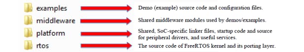
3.3 Building a Demo
The FreeRTOS BSP comes with rich demo applications and driver examples. To see what's available, browse to the BSP 'examples' folder and select your board, the i.MX 6SoloX SABRE board (.
To learn more about demo applications or driver examples, open the FreeRTOS
i.MX 6SoloX Demo Application User's Guide, located in
If one or more of the demo applications or driver examples sounds interesting, you're probably wanting to know how you can build and debug yourself. The Getting Started Guide with FreeRTOS BSP provides easy, step-by-step instructions on how to configure, build, and debug demos for all toolchains supported by the BSP.
All examples are provided with projects for the following toolchains:
- IAR Embedded Workbench
- DS-5
- GNU toolchain for Arm® Cortex®-M with CMAKE builds system
Use IAR Embedded Workbench IDE
1. Build the platform library
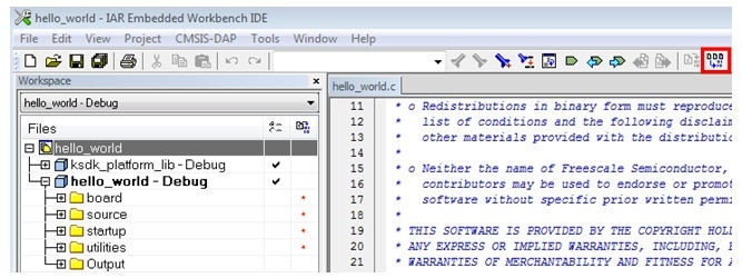
These steps show how to open a demo workspace in IAR Embedded Workbench, how to build the platform library required by the demo, and how to build the demo application. The example used below is for the hello_world demo, but similar steps can be applied to any demo in the KSDK.
-
Open demo workspace (*.eww file) in:
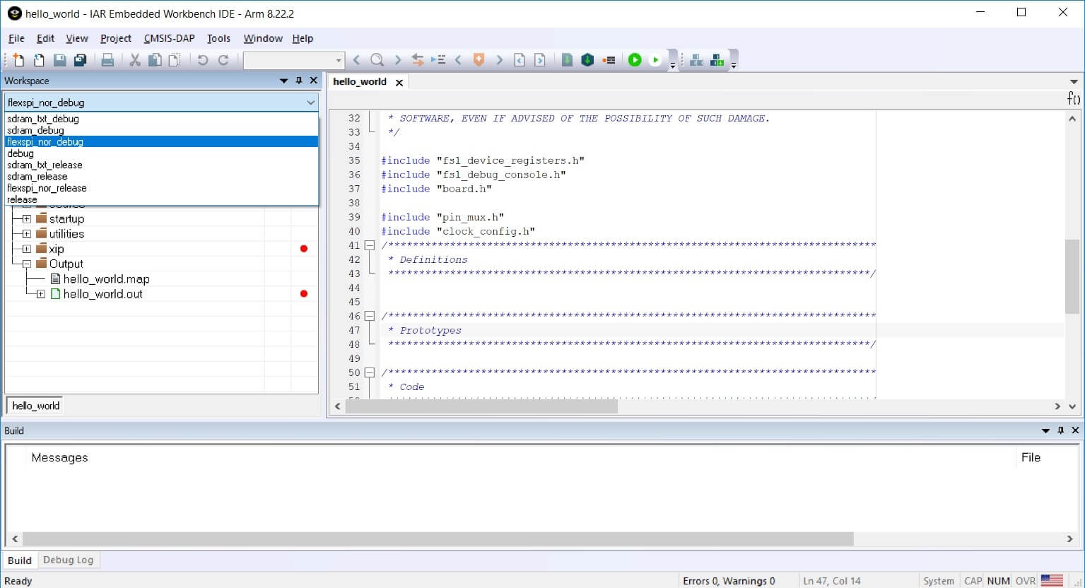
/examples/frdmkl46z/demo_apps/ /iar After the workspace is open, two projects are shown: one for the KSDK platform library and one for the demo. Also, the platform library project is bold, indicating that it is the active project. The active project can be changed at any time by right-clicking on the desired project and selecting "Set as Active" or via the build target drop-down at the top of the workspace browser.
-
There are two project configurations (build targets) supported for each KSDK project:
- Debug - Compiler optimization is set to low, and debug information is generated for the executable. This target should be selected for development and debug
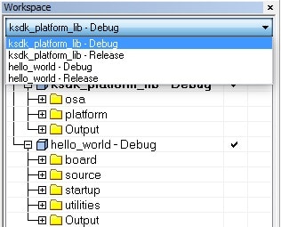
- Release - Compiler optimization is set to high, and debug information is not generated. This target should be selected for final application deployment. The tool allows you to select either the Debug or Release configuration on a per-project basis, but since the demo has a dependency on the platform library, which configuration is selected for the demo must also be selected for the platform library. Selecting a configuration in the drop-down also makes which project and configuration that is selected the active project. For this example, select the "ksdk_platform_lib — Debug" target
-
Click the "Make" button, highlighted in red below.
-
When the build is complete, the library (libksdk_platform.a) is generated in one of the following directories, according to the chosen build target:
/lib/ksdk_platform_lib/iar/KL46Z4/debug /lib/ksdk_platform_lib/iar/KL46Z4/release
2. Build a Demo Application
The KSDK demo applications are built upon the software building blocks provided in the Kinetis SDK platform library, built in the previous section. If the platform library is not present, the linker displays an error indicating that it cannot find the library. An easy way to check whether the library is present is to expand the Output folder in the ksdk_platform_lib project. If the platform library binary is not built and present, follow the steps on page 1 to build it. Otherwise, continue with the following steps to build the desired demo application.
-
If not already done, open the desired demo application workspace (*.eww file). This example's workspace file is located in:
/examples/frdmkl46z/demo_apps/hello_world/iar -
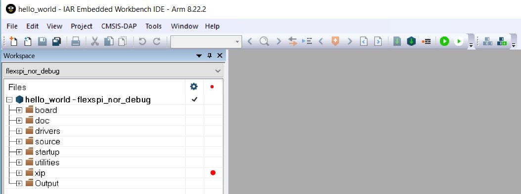
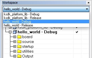
Select the desired build target from the drop-down. For this example, select the "hello_world — Debug" target
-
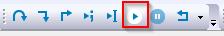
To build the demo application, click the "Make" button, highlighted in red below
-
The build will complete without errors
3. Run a Demo Application
The FRDM-KL46Z board comes loaded with the mbed/CMSIS-DAP debug interface from the factory. If you have changed the debug OpenSDA application on your board, visit opensda for information on updating or restoring your board to the factory state.
-
Connect the development platform to your PC via USB cable between the "SDAUSB" USB port on the board and the PC USB connector
-
Open the terminal application on the PC (such as PuTTY or TeraTerm) and connect to the debug COM port you determined earlier. Configure the terminal with these settings:
- 115200 baud rate
- No parity
- 8 data bits
- 1 stop bit
-
Click the "Download and Debug" button to download the application to the target.

-
The application is then downloaded to the target and automatically runs to the main() function
-
Run the code by clicking the "Go" button to start the application

-
The hello_world application is now running and a banner is displayed on the terminal. If this is not the case, check your terminal settings and connections

Using DS-5 IDE
This section describes the steps required to build demo applications provided in the FreeRTOS BSP. The hello_world demo for i.MX 6SoloX SABRE board is used as an example, though these steps can be applied to any board, demo or example application in the FreeRTOS BSP.
-
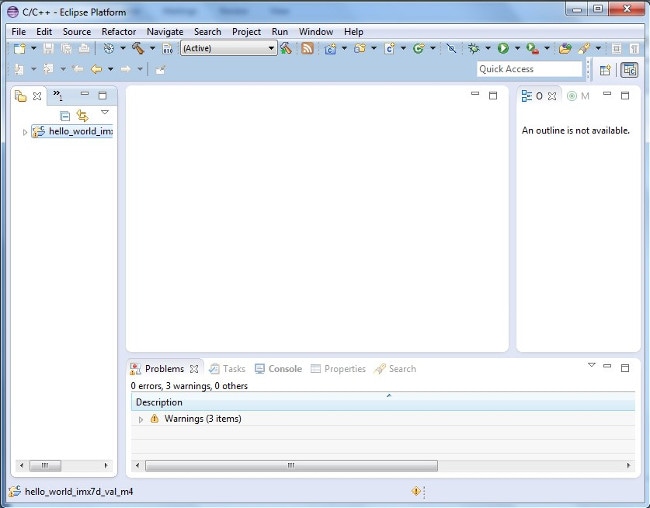
Open Arm DS-5 IDE installed on your PC:
-
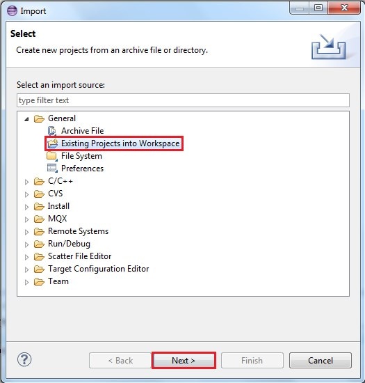
Select “File->Import” from the DS-5 IDE menu. In the window that appears, expand the “General” folder and select “Existing Projects into Workspace”. Then, click the “Next” button
-
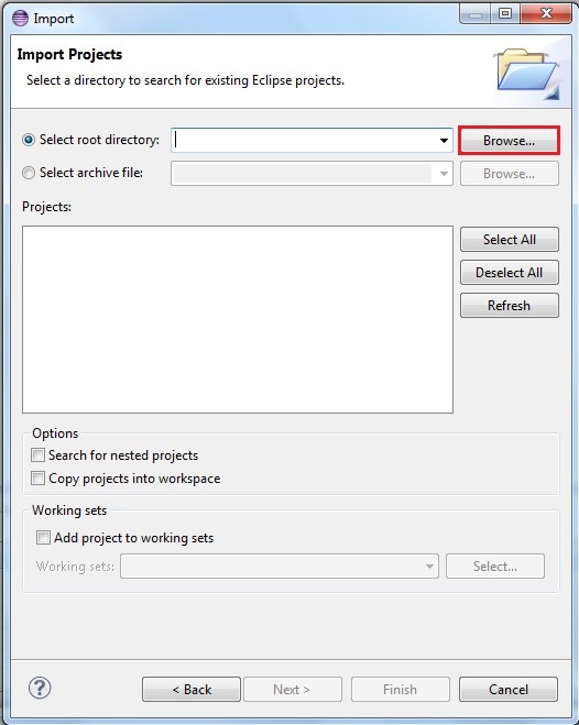
Click the “Browse” button next to the “Select root directory:” option
-
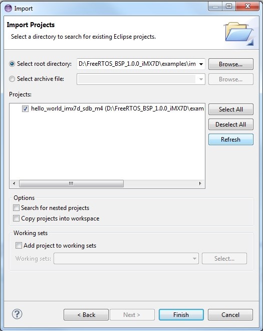
Point to the hello_world demo for the appropriate device, which can be found using this path:
/examples/ /demo_apps/hello_world/ds5 For this example, the specific location is:
/ examples/imx6sx_sdb_m4/demo_apps/hello_world/ds5 -
After pointing to the correct directory, your “Import Projects” window should look like the figure below. Click the “Finish” button
-
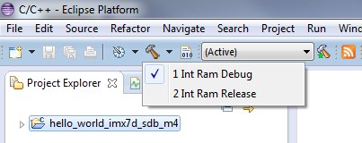
There are two project configurations (build targets) supported for each this project:
- Int Ram Debug – Compiler optimization is set to low, and debug information is generated for the executable. This target should be selected for development and debug
- Int Ram Release – Compiler optimization is set to high, and debug information is not generated. This target should be selected for final application deployment
-
Choose the appropriate build target, “Int Ram Debug” or “Int Ram Release”, by clicking the downward facing arrow next to the hammer icon, as shown below. For this example, select the “Int Ram Debug” target
-
The demo starts building after the build target is selected. To rebuild the demo in the future, click the hammer icon (assuming the same build target is chosen)
-
The build result can be found at
/examples/ /demo_apps/ /ds5/ . - The *.axf file contains the debug information of the demo application. It can be used for software debugging;
-
*.bin file can be generated from *.axf file using fromelf.exe tool in
\sw\ARMCompiler5.05u1\bin with the DS-5 Command Prompt. fromelf --bin --output=.bin .axf
Use Arm® GCC
1. Set Up Toolchain
This section contains the steps to install the necessary components required to build and run a KSDK demo application with the Arm GCC toolchain, as supported by the Kinetis SDK. There are many ways to use Arm GCC tools, but this example focuses on a Windows environment. Though not discussed here, GCC tools can also be used with both Linux OS and Mac OSX.
Install GCC Arm Embedded Toolchain
Download and run the installer from gcc-arm-embedded . This is the actual toolchain (i.e., compiler, linker, etc.). The GCC toolchain should correspond to the latest supported version, as described in the Kinetis SDK Release Notes.
Install MinGW
The Minimalist GNU for Windows (MinGW) development tools provide a set of tools that are not dependent on third-party C-Runtime DLLs (such as Cygwin). The build environment used by the KSDK does not use the MinGW build tools, but does leverage the base install of both MinGW and MSYS. MSYS provides a basic shell with a Unix-like interface and tools.
-
Download the latest MinGW mingw-get-setup installer from sourceforge .
-
Run the installer. The recommended installation path is C:\MinGW, however, you may install to any location
-
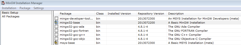
Ensure that the "mingw32-base" and "msys-base" are selected under Basic Setup
-
Click "Apply Changes" in the "Installation" menu and follow the remaining instructions to complete the installation
-
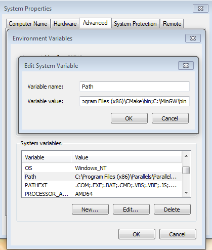
Add the appropriate item to the Windows operating system Path environment variable. It can be found under
Control Panel -> System and Security -> System -> Advanced
                    System Settings
in the "Environment Variables..." section. The path is:\bin Assuming the default installation path, C:\MinGW, an example is shown below. If the path is not set correctly, the toolchain does not work.
-
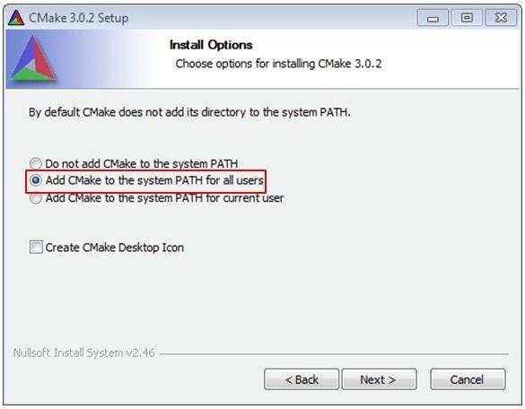
Download CMake 3.0.x from cmake .
-
Install CMake, ensuring that the option "Add CMake to system PATH" is selected when installing. It's up to the user to select whether it's installed into the PATH for all users or just the current user. In this example, the assumption is that it's installed for all users
-
Follow the remaining instructions of the installer
-
You may need to reboot your system for the PATH changes to take effect
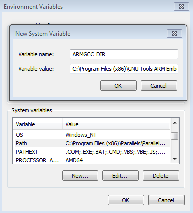
Add a New Environment Variable for ARMGCC_DIR
Create a new system environment variable and name it
ARMGCC_DIR. The value of this variable should point to the Arm GCC Embedded
tool chain installation path, which, for this example, is:
C:\Program Files (x86)\GNU Tools Arm Embedded\4.8 2014q3
Reference the installation folder of the GNU Arm GCC Embedded tools for the exact pathname of your installation.
Install CMake
2. Build the Platform Library
-
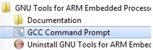
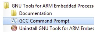
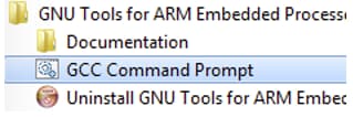
Open a GCC Arm Embedded tool chain command window. To launch the window, from the Windows operating system Start menu, go to "Programs -> GNU Tools Arm Embedded " and select "GCC Command Prompt".
-
Change the directory of the command window to the platform library directory in the KSDK:
/lib/ksdk_platform_lib/armgcc/KL46Z4 -
There are two project configurations (build targets) supported for each KSDK project:
- Debug — Compiler optimization is set to low, and debug information is generated for the executable. This target should be selected for development and debug
- Release — Compiler optimization is set to high, and debug information is not generated. This target should be selected for final application deployment
There are batch files provided to build both configurations. For this example, the "Debug" target is built and "build_debug.bat" is typed on the command line. If the "Release" target is desired, type the "build_release.bat" instead. Alternatively, if using the command line is not desired, you can double click on the batch files from Windows Explorer.

-
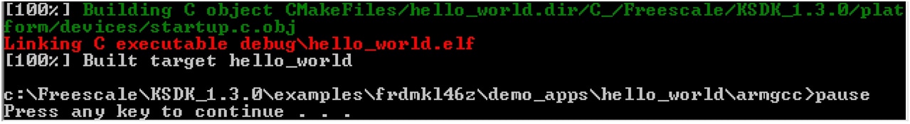
When the build finishes, the output looks like the image below(with KL46Z4 in place of K64F12)

-
The library (libksdk_platform.a) is generated in one of these directories, according to the build target:
/lib/ksdk_platform_lib/armgcc/KL46Z4/debug /lib/ksdk_platform_lib/armgcc/KL46Z4/release
3. Build a Demo Application
KSDK demo applications require that the platform library for the same build target (Debug or Release) is present. Please ensure that you follow the steps in section 7.2 prior to attempting to build a demo application.
To build a demo application, follow these steps.
-
If not already running, open a GCC Arm Embedded tool chain command window. To launch the window, from the Windows operating system Start menu, go to "Programs -> GNU Tools Arm Embedded " and select "GCC Command Prompt".
-
Change the directory to the demo application project directory, which has a path like this:
/examples/frdmkl46z/demo_apps/ /armgcc For this example, the exact path is:
/examples/frdmkl46z/demo_apps/hello_world/armgcc -
Type "build_debug.bat" on the command line or double click on the "build_debug.bat" file in Windows operating system Explorer to perform the build. The output is shown in this figure:
4. Run a Demo Application
The GCC tools require a J-Link debug interface. To update the OpenSDA firmware on your board to the latest J-Link app, visit opensda. After installing the J-Link OpenSDA application, download the J-Link driver and software package from segger .
-
Connect the development platform to your PC via USB cable between the "SDAUSB" USB port on the board and the PC USB connector
-
Open the terminal application on the PC (such as PuTTY or TeraTerm) and connect to the debug COM port you determined earlier. Configure the terminal with these settings:
- 115200 baud rate
- No parity
- 8 data bits
- 1 stop bit
-
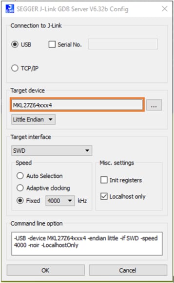
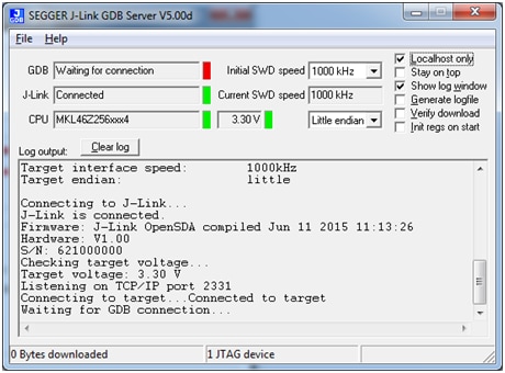
Open the J-Link GDB Server application. Assuming the J-Link software is installed, the application can be launched by going to the Windows operating system Start menu and selecting "Programs -> SEGGER -> J-Link J-Link GDB Server".
-
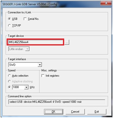
Modify the settings as shown below. The target device selection chosen for this example is the "MKL46Z128xxx4"
-
After it is connected, the screen should resemble this figure:
-
If not already running, open a GCC Arm Embedded tool chain command window. To launch the window, from the Windows operating system Start menu, go to "Programs -> GNU Tools Arm Embedded " and select "GCC Command Prompt".
-
Change to the directory that contains the demo application output. The output can be found in using one of these paths, depending on the build target selected:
/examples/ /demo_apps/ /armgcc/debug /examples/ /demo_apps/ /armgcc/release For this example, the path is:
/examples/frdmkl46z/demo_apps/hello_world/armgcc/debug -
Run the command "arm-none-eabi-gdb.exe
.elf". For this example, it is "arm-none-eabi-gdb.exe hello_world.elf". The example image below displays the building of the frdmkl46z hello_world application as an example. 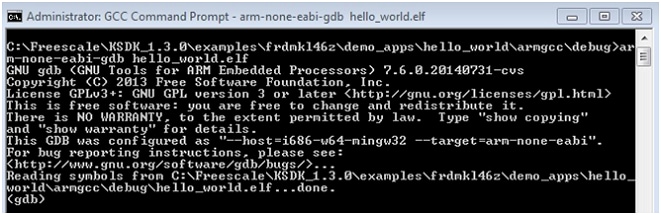
-
Run these commands:
- "target remote localhost: 2331"
- "monitor reset"
- "monitor halt"
- "load"
- "monitor reset"
-
The application is now downloaded and halted at the reset vector. Execute the "monitor go" command to start the demo application
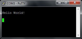
The hello_world application is now running and a banner is displayed in the terminal window
Use IAR Embedded Workbench IDE
1. Build the platform library
These steps show how to open a demo workspace in IAR Embedded Workbench, how to build the platform library required by the demo, and how to build the demo application. The example used below is for the hello_world demo, but similar steps can be applied to any demo in the KSDK.
-
Open demo workspace (*.eww file) in:
/examples/frdmkl46z/demo_apps/ /iar After the workspace is open, two projects are shown: one for the KSDK platform library and one for the demo. Also, the platform library project is bold, indicating that it is the active project. The active project can be changed at any time by right-clicking on the desired project and selecting "Set as Active" or via the build target drop-down at the top of the workspace browser.
-
There are two project configurations (build targets) supported for each KSDK project:
- Debug - Compiler optimization is set to low, and debug information is generated for the executable. This target should be selected for development and debug
- Release - Compiler optimization is set to high, and debug information is not generated. This target should be selected for final application deployment. The tool allows you to select either the Debug or Release configuration on a per-project basis, but since the demo has a dependency on the platform library, which configuration is selected for the demo must also be selected for the platform library. Selecting a configuration in the drop-down also makes which project and configuration that is selected the active project. For this example, select the "ksdk_platform_lib — Debug" target
-
Click the "Make" button, highlighted in red below.
-
When the build is complete, the library (libksdk_platform.a) is generated in one of the following directories, according to the chosen build target:
/lib/ksdk_platform_lib/iar/KL46Z4/debug /lib/ksdk_platform_lib/iar/KL46Z4/release
2. Build a Demo Application
The KSDK demo applications are built upon the software building blocks provided in the Kinetis SDK platform library, built in the previous section. If the platform library is not present, the linker displays an error indicating that it cannot find the library. An easy way to check whether the library is present is to expand the Output folder in the ksdk_platform_lib project. If the platform library binary is not built and present, follow the steps on page 1 to build it. Otherwise, continue with the following steps to build the desired demo application.
-
If not already done, open the desired demo application workspace (*.eww file). This example's workspace file is located in:
/examples/frdmkl46z/demo_apps/hello_world/iar -
Select the desired build target from the drop-down. For this example, select the "hello_world — Debug" target
-
To build the demo application, click the "Make" button, highlighted in red below
-
The build will complete without errors
3. Run a Demo Application
The FRDM-KL46Z board comes loaded with the mbed/CMSIS-DAP debug interface from the factory. If you have changed the debug OpenSDA application on your board, visit opensda for information on updating or restoring your board to the factory state.
-
Connect the development platform to your PC via USB cable between the "SDAUSB" USB port on the board and the PC USB connector
-
Open the terminal application on the PC (such as PuTTY or TeraTerm) and connect to the debug COM port you determined earlier. Configure the terminal with these settings:
- 115200 baud rate
- No parity
- 8 data bits
- 1 stop bit
-
Click the "Download and Debug" button to download the application to the target.
-
The application is then downloaded to the target and automatically runs to the main() function
-
Run the code by clicking the "Go" button to start the application
-
The hello_world application is now running and a banner is displayed on the terminal. If this is not the case, check your terminal settings and connections
Using DS-5 IDE
This section describes the steps required to build demo applications provided in the FreeRTOS BSP. The hello_world demo for i.MX 6SoloX SABRE board is used as an example, though these steps can be applied to any board, demo or example application in the FreeRTOS BSP.
-
Open Arm DS-5 IDE installed on your PC:
-
Select “File->Import” from the DS-5 IDE menu. In the window that appears, expand the “General” folder and select “Existing Projects into Workspace”. Then, click the “Next” button
-
Click the “Browse” button next to the “Select root directory:” option
-
Point to the hello_world demo for the appropriate device, which can be found using this path:
/examples/ /demo_apps/hello_world/ds5 For this example, the specific location is:
/ examples/imx6sx_sdb_m4/demo_apps/hello_world/ds5 -
After pointing to the correct directory, your “Import Projects” window should look like the figure below. Click the “Finish” button
-
There are two project configurations (build targets) supported for each this project:
- Int Ram Debug – Compiler optimization is set to low, and debug information is generated for the executable. This target should be selected for development and debug
- Int Ram Release – Compiler optimization is set to high, and debug information is not generated. This target should be selected for final application deployment
-
Choose the appropriate build target, “Int Ram Debug” or “Int Ram Release”, by clicking the downward facing arrow next to the hammer icon, as shown below. For this example, select the “Int Ram Debug” target
-
The demo starts building after the build target is selected. To rebuild the demo in the future, click the hammer icon (assuming the same build target is chosen)
-
The build result can be found at
/examples/ /demo_apps/ /ds5/ . - The *.axf file contains the debug information of the demo application. It can be used for software debugging;
-
*.bin file can be generated from *.axf file using fromelf.exe tool in
\sw\ARMCompiler5.05u1\bin with the DS-5 Command Prompt. fromelf --bin --output=.bin .axf
Use ARM® GCC
1. Set Up Toolchain
This section contains the steps to install the necessary components required to build and run a KSDK demo application with the Arm GCC toolchain, as supported by the Kinetis SDK. There are many ways to use Arm GCC tools, but this example focuses on a Windows environment. Though not discussed here, GCC tools can also be used with both Linux OS and Mac OSX.
Install GCC Arm Embedded Toolchain
Download and run the installer from gcc-arm-embedded . This is the actual toolchain (i.e., compiler, linker, etc.). The GCC toolchain should correspond to the latest supported version, as described in the Kinetis SDK Release Notes.
Install MinGW
The Minimalist GNU for Windows (MinGW) development tools provide a set of tools that are not dependent on third-party C-Runtime DLLs (such as Cygwin). The build environment used by the KSDK does not use the MinGW build tools, but does leverage the base install of both MinGW and MSYS. MSYS provides a basic shell with a Unix-like interface and tools.
-
Download the latest MinGW mingw-get-setup installer from sourceforge .
-
Run the installer. The recommended installation path is C:\MinGW, however, you may install to any location
-
Ensure that the "mingw32-base" and "msys-base" are selected under Basic Setup
-
Click "Apply Changes" in the "Installation" menu and follow the remaining instructions to complete the installation
-
Add the appropriate item to the Windows operating system Path environment variable. It can be found under
Control Panel -> System and Security -> System -> Advanced
                        System Settings
in the "Environment Variables..." section. The path is:\bin Assuming the default installation path, C:\MinGW, an example is shown below. If the path is not set correctly, the toolchain does not work.
-
Download CMake 3.0.x from cmake .
-
Install CMake, ensuring that the option "Add CMake to system PATH" is selected when installing. It's up to the user to select whether it's installed into the PATH for all users or just the current user. In this example, the assumption is that it's installed for all users
-
Follow the remaining instructions of the installer
-
You may need to reboot your system for the PATH changes to take effect
Add a New Environment Variable for ARMGCC_DIR
Create a new system environment variable and name it
ARMGCC_DIR. The value of this variable should point to the Arm GCC Embedded
tool chain installation path, which, for this example, is:
C:\Program Files (x86)\GNU Tools Arm Embedded\4.8 2014q3
Reference the installation folder of the GNU Arm GCC Embedded tools for the exact pathname of your installation.
Install CMake
2. Build the Platform Library
-
Open a GCC Arm Embedded tool chain command window. To launch the window, from the Windows operating system Start menu, go to "Programs -> GNU Tools Arm Embedded " and select "GCC Command Prompt".
-
Change the directory of the command window to the platform library directory in the KSDK:
/lib/ksdk_platform_lib/armgcc/KL46Z4 -
There are two project configurations (build targets) supported for each KSDK project:
- Debug — Compiler optimization is set to low, and debug information is generated for the executable. This target should be selected for development and debug
- Release — Compiler optimization is set to high, and debug information is not generated. This target should be selected for final application deployment
There are batch files provided to build both configurations. For this example, the "Debug" target is built and "build_debug.bat" is typed on the command line. If the "Release" target is desired, type the "build_release.bat" instead. Alternatively, if using the command line is not desired, you can double click on the batch files from Windows Explorer.
-
When the build finishes, the output looks like the image below(with KL46Z4 in place of K64F12)
-
The library (libksdk_platform.a) is generated in one of these directories, according to the build target:
/lib/ksdk_platform_lib/armgcc/KL46Z4/debug /lib/ksdk_platform_lib/armgcc/KL46Z4/release
3. Build a Demo Application
KSDK demo applications require that the platform library for the same build target (Debug or Release) is present. Please ensure that you follow the steps in section 7.2 prior to attempting to build a demo application.
To build a demo application, follow these steps.
-
If not already running, open a GCC Arm Embedded tool chain command window. To launch the window, from the Windows operating system Start menu, go to "Programs -> GNU Tools Arm Embedded " and select "GCC Command Prompt".
-
Change the directory to the demo application project directory, which has a path like this:
/examples/frdmkl46z/demo_apps/ /armgcc For this example, the exact path is:
/examples/frdmkl46z/demo_apps/hello_world/armgcc -
Type "build_debug.bat" on the command line or double click on the "build_debug.bat" file in Windows operating system Explorer to perform the build. The output is shown in this figure:
4. Run a Demo Application
The GCC tools require a J-Link debug interface. To update the OpenSDA firmware on your board to the latest J-Link app, visit opensda. After installing the J-Link OpenSDA application, download the J-Link driver and software package from segger .
-
Connect the development platform to your PC via USB cable between the "SDAUSB" USB port on the board and the PC USB connector
-
Open the terminal application on the PC (such as PuTTY or TeraTerm) and connect to the debug COM port you determined earlier. Configure the terminal with these settings:
- 115200 baud rate
- No parity
- 8 data bits
- 1 stop bit
-
Open the J-Link GDB Server application. Assuming the J-Link software is installed, the application can be launched by going to the Windows operating system Start menu and selecting "Programs -> SEGGER -> J-Link J-Link GDB Server".
-
Modify the settings as shown below. The target device selection chosen for this example is the "MKL46Z128xxx4"
-
After it is connected, the screen should resemble this figure:
-
If not already running, open a GCC Arm Embedded tool chain command window. To launch the window, from the Windows operating system Start menu, go to "Programs -> GNU Tools Arm Embedded " and select "GCC Command Prompt".
-
Change to the directory that contains the demo application output. The output can be found in using one of these paths, depending on the build target selected:
/examples/ /demo_apps/ /armgcc/debug /examples/ /demo_apps/ /armgcc/release For this example, the path is:
/examples/frdmkl46z/demo_apps/hello_world/armgcc/debug -
Run the command "arm-none-eabi-gdb.exe
.elf". For this example, it is "arm-none-eabi-gdb.exe hello_world.elf". The example image below displays the building of the frdmkl46z hello_world application as an example.
-
Run these commands:
- "target remote localhost: 2331"
- "monitor reset"
- "monitor halt"
- "load"
- "monitor reset"
-
The application is now downloaded and halted at the reset vector. Execute the "monitor go" command to start the demo application
The hello_world application is now running and a banner is displayed in the terminal window
3.4 Run application using U-Boot
This section describes the steps to run application using an SD card with prebuilt U-Boot image for i.MX processor. For more information about how to write the U-Boot image to SD card and create FAT file system partition, refer to Linux BSP package.
3.5 Example Demo
Demo and example applications are provided to demonstrate peripheral drivers, FreeRTOS kernel, RPMsg usage and to highlight the main features of the i.MX 6SoloX processor.
The FreeRTOS BSP provides two types of software applications:
- Demos: Applications intended to highlight key functions of the Arm® Cortex®-M4 Core in i.MX 6SoloX SoC, focusing on a particular use case on FreeRTOS OS
- Examples: Simple applications intended to concisely illustrate how to use the peripheral drivers of the FreeRTOS BSP in the bare metal environment
The Sensor Demo i.MX 6SoloX is a simple demonstration program that uses the FreeRTOS and a set of drivers provided by NXP. It can get the current gravitational acceleration and magnetic field strength of the board. The purpose of this demo is to show how to use the I²C driver as a Controller to communication with other I²C Targets.
In the second terminal emulator for M4 core, you should see text indicating the sensor example is running (e.g., below). Choose one of the sensor demos and affect the given sensor by moving the board or moving something magnetic near it.
-------------- i.MX 6SoloX SABRE on board sensor example--------------
Select the sensor demo you want to run:
The user is prompted to enter which sensor they want to communicate with:
[1].MMA8451Q 3-Axis Digital Accelerometer Polling Demo
[2].MMA8451Q 3-Axis Digital Accelerometer Interrupt Demo
[3].MAG3110 3-Axis Digital Magnetometer Polling Demo
[4].MAG3110 3-Axis Digital Magnetometer Interrupt Demo
As is shown on the log, the RPMsg Controller (Cortex-A9 Linux OS) and Remote (Cortex-M4 FreeRTOS OS) perform a name service handshake to create the communication channel. The M4 channel address is 1, and the A9 channel address is 1024. A9 begins to send the first data to M4. After receiving the data, M4 adds 1 to it and sends it back to A9. A9 responds with the same behavior. The loop continues to demonstrate the stability of RPMsg communication.
After the boot process succeeds, the Arm Cortex-M4 terminal displays the following information:
RPMSG PingPong FreeRTOS RTOS API Demo...
RPMSG Init as Remote
After the Linux pingpong controller side module is installed, the Arm Cortex-M4 terminal displays the following information:
Name service handshake is done, M4 has setup a rpmsg channel [1--->
    1024]
Get Data From Controller Side : 0
Get Data From Controller Side : 2
Get Data From Controller Side : 4
Get Data From Controller Side : 6
Get Data From Controller Side : 8
......
As is shown on the log, the pingpong demo runs in an infinite loop. Reboot the board to stop it.
4. Exploration
4.1 Key Features Demo in Linux
With Linux® running on the i.MX platform, you can evaluate special features that i.MX SoCs provide:
Power Management
There are three main power management techniques on i.MX boards:
- Suspend and resume commands
- CPU frequency scaling
- Bus frequency scaling
After Linux® setup, for more details about developing applications in user space. Please see i.MX6 Linux® Reference Manual.
Multimedia
After Linux® setup, for more details about developing applications in user space. Please see i.MX6 Linux® Reference Manual.
Graphics
- For more details, go to Chapter 8 of i.MX Linux® User’s Guide
-
For more details of graphic APIs and driver support, see i.MX6
Graphics User’s Guide
- The purpose of this document is to provide information on graphic APIs and driver support. Each chapter describes a specific set of APIs or driver integration as well as specific hardware acceleration customization. The target audiences for this document are developers writing graphics applications or video drivers
- i.MX G2D API
- i.MX 6 EGL and OGL Extension Support
- For more details of Video Processing Unit, see i.MX VPU programming interface Linux® Reference Manual
Security
- For more details, go to Chapter 9 of i.MX Linux® User’s Guide
- For details of secure system upgrade, read i.MX Linux® High Assurance Boot User’s Guide
Connectivity
- Bluetooth support works best with a USB dongle with either BlueZ4 or BlueZ5.
- Broadcom Wi-Fi and Bluetooth wireless technology support require the Broadcom firmware package download from imx6tools. The Broadcom device drivers are integrated into the kernel but to function require the firmware package download and integration.
- For more details, go to Chapter 10 of i.MX Linux® User’s Guide
There are three main power management techniques on i.MX boards:
- Suspend and resume commands
- CPU frequency scaling
- Bus frequency scaling
After Linux® setup, for more details about developing applications in user space. Please see i.MX6 Linux® Reference Manual.
4.2 Application development
After Linux® setup, for more details about developing applications in user space. Please see i.MX6 Linux® Reference Manual.
There are a lot of program environment.
4.3 Yocto Project
NXP Yocto Project User's Guide covers how to set up the Linux® host machine, how to run and configure a Yocto Project, generate an image, and generate a rootfs.
For more details, see NXP Yocto Project User’s Guide.
Tera Term Terminal
Tera Term Terminal
Tera Term is a very popular open source terminal emulation application. This program can be used to display information sent from your NXP development platform's virtual serial port.
- Download Tera Term from SourceForge. After the download, run the installer and then return to this webpage to continue
-
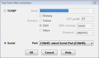
Launch Tera Term. The first time it launches, it will show you the following
dialog. Select the serial option. Assuming your board is plugged in, there
should be a
COMport automatically populated in the list -
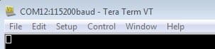
Configure the serial port settings (using the
COMport number identified earlier) to 115200 baud rate, 8 data bits, no parity and 1 stop bit. To do this, go to Setup → Serial Port and change the settings - Verify that the connection is open. If connected, Tera Term will show something like below in it's title bar
- You're ready to go
PuTTY Terminal
PuTTY Terminal
PuTTY is a popular terminal emulation application. This program can be used to display information sent from your NXP development platform's virtual serial port.
- Download PuTTY using the button below. After the download, run the installer and then return to this webpage to continue
- Launch PuTTY by either double clicking on the *.exe file you downloaded or from the Start menu, depending on the type of download you selected
-
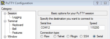
Configure In the window that launches, select the Serial radio button and
enter the
COMport number that you determined earlier. Also enter the baud rate, in this case 115200 -
Click Open to open the serial connection. Assuming the board is connected
and you entered the correct
COMport, the terminal window will open. If the configuration is not correct, PuTTY will alert you - You're ready to go
Use Manufacturing Tool
Use Manufacturing Tool
Manufacturing Tool Tutorial - Android™
- Connect a USB cable from a computer running Windows OS to the USB OTG port on the board.
- Unzip the mfgtools.tar.gz file to a selected loation. The directory is named MFGTool-Dir in this example.
- Copy the BSP image to to the path: MFGTool-Dir/Profiles/Linux/OS Firmware/files/android/sabresd
- No dedicated boot DIP switches are reserved for serial download mode on i.MX 6 Quad/QuadPlus SABRE-SD board.One way is to change the SABRE-SD SW6 (boot) to 00001100 (from 1-8 bit) to enter download mode.
- Power on the board.
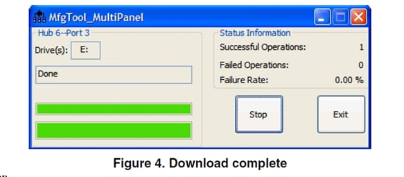
- Double-click the file *.vbs according to the target device.
- Click "Start" to start downloading. the status bar shows the download status. The download may take one to two minutes depending on the host machine.
- After the image downloading is done, set the boot switch to boot up the board according to the table in the next step.
For details, please refer to "3.3 Downloading Board Images" in i.MX Android™ Quick Start Guide
You can connect a USB cable from the debug UART port to the computer and open a serial communication program for for console output.
Using U-Boot
Using U-Boot
-
Preparing an SD card with prebuilt U-Boot image from Linux BSP packet for i.MX 6SoloX processor
-
Insert the SD card to the PC, and copy the application image (for example hello_world.bin) you want run to the FAT partition of the SD card
-
Safely remove the SD card from the PC
-
Insert the SD card to the target board. Make sure to use the default boot SD slot and double check the dip switch configuration. The default configuration of the validation board boots from SD1, and on SABRE board there is only one SD slot, which is used for boot
-
Connect the “DEBUG UART” slot on the board with your PC through the USB cable. The Windows OS installs the USB driver automatically, and the Ubuntu OS will find the serial devices as well
See Step 3 in Out of the Box for more instructions for serial communication application
-
Open a second terminal emulator on the i.MX 6SoloX Sabre board's second counted serial port. This is the Cortex-M4's serial console. Setting the speed to 115200 bit/s, data bits 8, no parity, and power on the board
-
Load the application image from the SD card to DDR RAM:
fatload mmc 2:1 0x7F8000.bin -
Flush cached content to DDR RAM:
dcache flush -
Copy Cortex-M4 image from DDR RAM to TCM:
cp.b 0x80000000 0x7F8000 0x8000 -
Flush cached content to TCM:
dcache flush -
Start the Cortex-M4 core from the TCM:
bootaux 0x7F8000
-
At the U-Boot prompt on the first terminal emulator, type the following commands to U-Boot. This copies the FreeRTOS memory image file from the first partition of the SD card into the Cortex-M4's tightly coupled memory (TCM) and releases the M4 from reset.
Some applications with the names ended by “DDR” or "ocram" in FreeRTOS BSP should be run in DDR or OCRAM. Those ended by "qspi" should boot from external QSPI flash.
For more instructions on how to boot from other storage, please read section 6.2 and 6.3 in Getting Started with FreeRTOS BSP for i.MX 6SoloX.
Support
Forums
Connect with other engineers and get expert advice on designing with the RD-IMX6SX-SABRE Evaluation Board on one of our community sites.
On this page
- 1.1
Get Familiar with the Board
- 1.2
Insert the SD Card (SD4)
- 1.3
Connect USB Debug Cable
- 1.4
Connect LVDS Panel
- 1.5
Connect Ethernet Cable (Optional)
- 1.6
Connect Power Supply
- 1.7
Congratulations Your Linux® is booted