Getting Started with KW47-LOC
Contents of this document
-
Plug It In
-
Get Software
-
Build and Run
-
Create
-
MCUXpresso Developer Experience
Sign in to save your progress. Don't have an account? Create one.
Purchase your Localization Board for KW47 Bluetooth Channel Sounding MCU
1. Plug It In
Take your board for a test drive! In the following steps, you may either watch the sequence in a short video, or follow the detailed actions listed below.
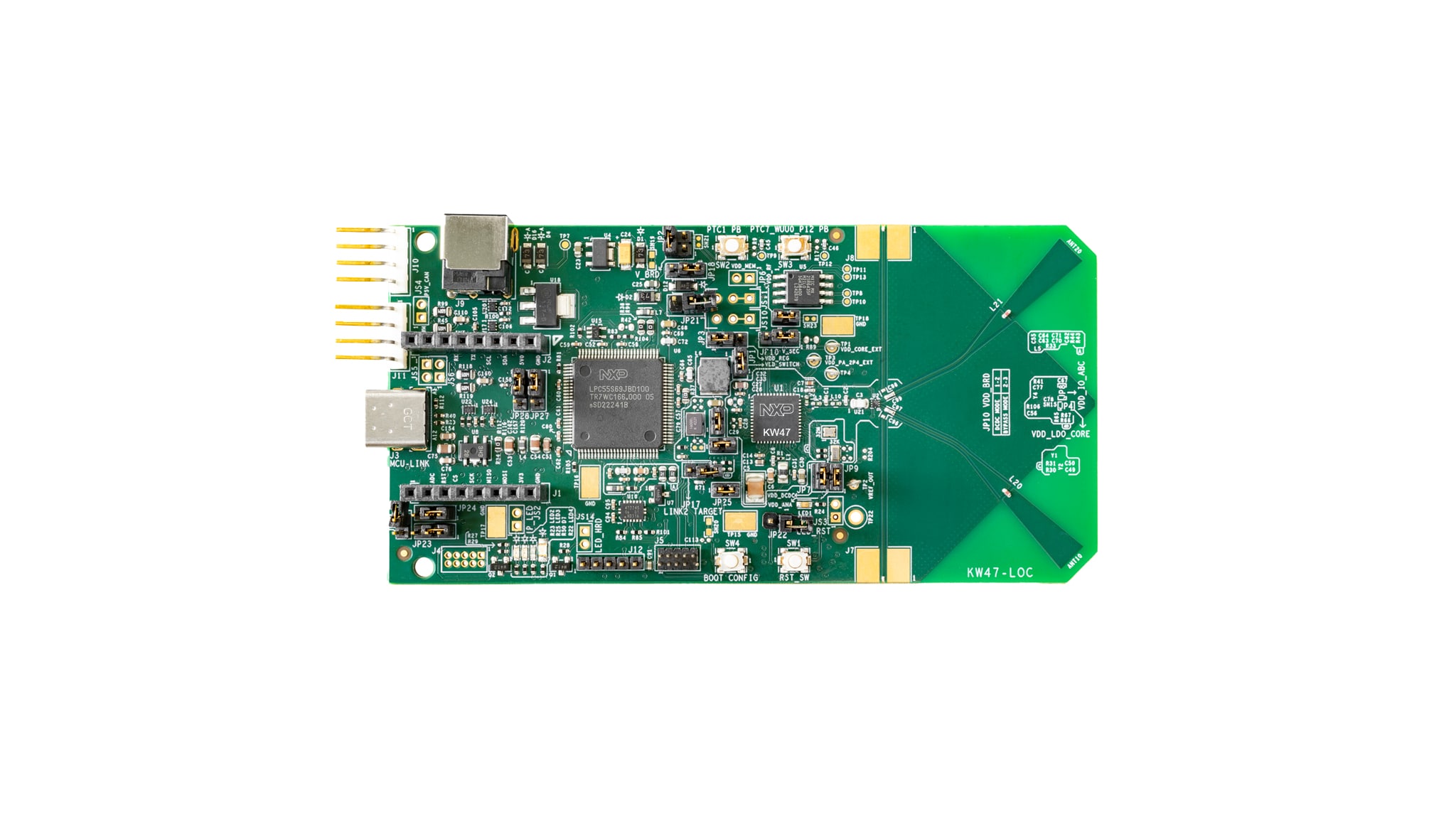
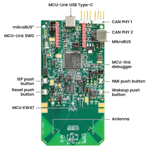
1.1 Get Familiar with the Board
The KW47-LOC board is pre-programmed with a wireless localization demo. This serves as a sanity check to verify that the device is working as expected, right out of the box.
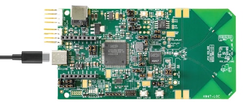
1.2 Plug In the Board
For this step, you will need two KW47-LOC boards. Connect a USB Type‑C cable from connector J3 to a host
computer or power supply to power up the board
and run the demo program. At this point, you should see the Blue LED blinking at a steady rhythm. Follow the steps
shown in the video to run the demo.
2. Get Software
2.1 Install Your Toolchain
NXP offers a toolchain called MCUXpresso for Visual Studio (VS) Code. Please download MCUXpresso for VS Code v25.09 or higher by clicking the button below.
Learn how to install VS Code onto your host PC by following the MCUXpresso tutorial.
2.2 Jump Start Your Design with the MCUXpresso SDK
The NXP extension provides tools that add software repositories to the VS Code workspace. This software repository can be provided from three sources:
- Remote Git URL
- NXP MCUXpresso archive file
- Existing Git folder
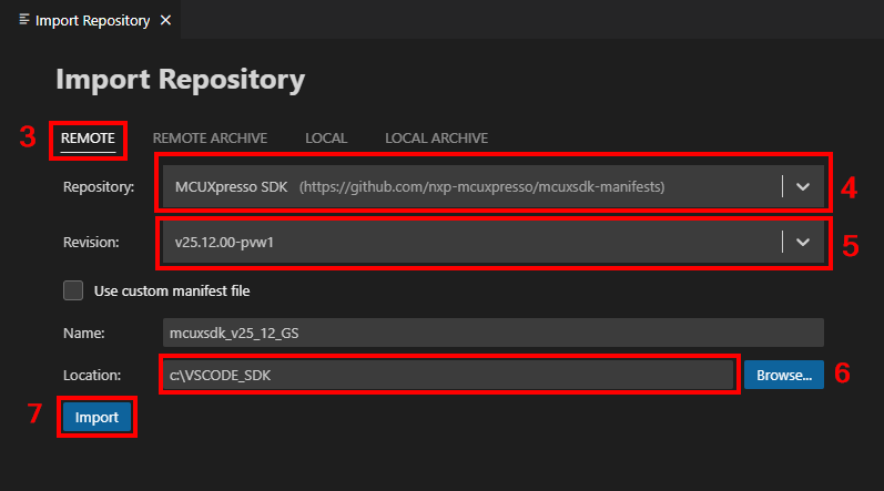
In this section, you will learn how to import the MCUXpresso SDK using the remote Git repository option. To import the repository this way, follow these steps:
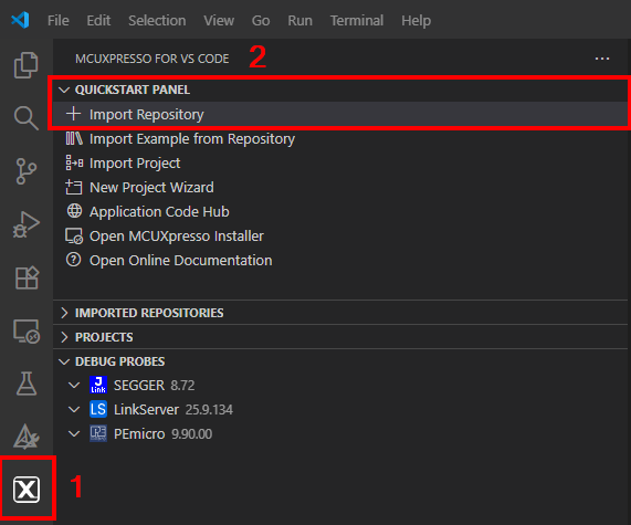
- Click the MCUXpresso extension Icon
- Click the "QUICKSTART PANEL" tab and then click the "Import Repository" button. After pressing that button a new import window will appear
- Select the "Remote" option to import the provided SDK files
- Browse to the Repository options by clicking the arrow button and search for "MCUXpresso SDK" option
- Click the arrow button for Revision and search for version "v25.09.00" or newer
- Click "Browse" for the Location folder and select a common destination folder to store your SDK
- Enter a name for the new SDK
- Click the "Import" button and wait for the installation
2.3 MCUXpresso Config Tools
The MCUXpresso Config Tool is an integrated suite of tools that guide users in creating new MCUXpresso SDK projects and also provides pin and clock tools to generate initialization C code for custom board support. The tool is fully integrated as a part of MCUXpresso integrated development environment (IDE) or as a separate tool (if using a different IDE).
Click the Get MCUXpresso Config Tools button below to get the installer.
2.4 Programming and Provisioning Tools
The MCUXpresso Secure Provisioning (SEC) Tool is a graphical user interface (GUI)-based application provided to simplify the generation and provisioning of bootable executables on NXP microcontroller unit (MCU) devices. It supports secure programming and device provisioning for NXP's microcontrollers at the production stage. We recommend that all users to begin with MCUXpresso SEC tool for trials run and mass production use.
After downloading the tool, find the user guide under the ‘Help’ tab. Then follow the instructions for your board in the ‘Processor-specific Workflow’ chapter.

Note: For advanced users who need a more customizable setup, we also off a command-line tool that is useful when interfacing with a custom or partner programming tool. The Secure Provisioning Software Developent Kit (SPSDK) is an open-source development kit with its source code released on GitHub and PyPI.
2.5 Installing IoT Toolbox
NXP's IoT Toolbox is a versatile mobile application designed to support wireless connectivity demonstrations and testing. It provides an intuitive interface to interact with the NXP development platform. You will need this app to continue with the next sections of this Getting Started guide.
Get started by installing the interactive IoT Toolbox from one of the following platforms onto your smartphone:
3. Build and Run
The following steps guide you through the wireless localization demo application using MCUXpresso for VS Code extension for the Arm® Cortex®-M33 application. The MCUXpresso extension for VS Code installation and the SDK for the KW-Series can be found in the "Get Software" section of this Getting Started guide.
3.1 Updating the NBU Firmware
Before running any wireless demo, the narrow band unit (NBU) firmware must be updated according to its SDK version.
- Connect your KW47-LOC board to your PC using a USB Type‑C cable
- Open the LinkFlash tool that you installed in Section 2.1 (this tool comes included with the
LinkServer
component and the default path for this tool is "
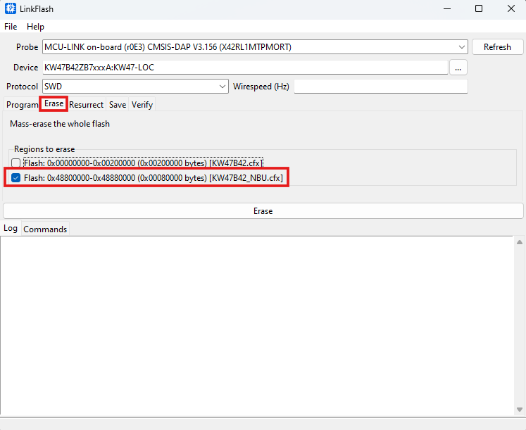
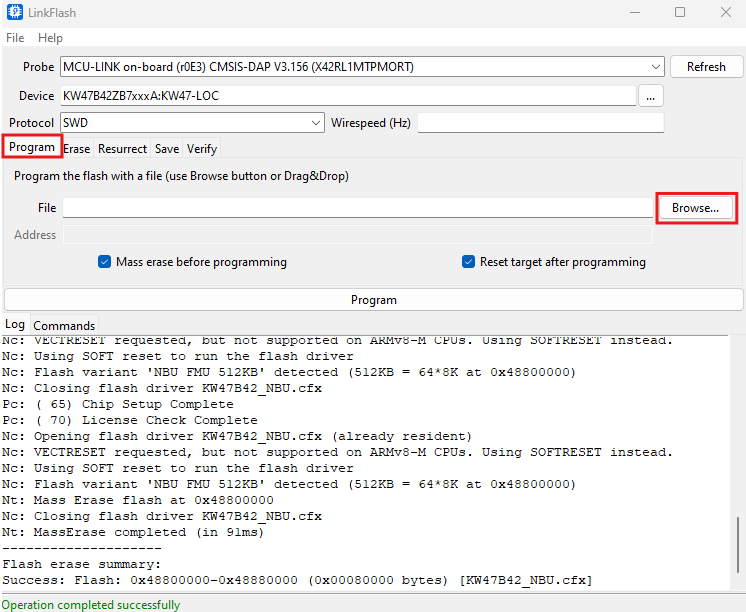
C:\nxp\LinkServer_XX.XX.XX\LinkFlash.exe") - Verify that your board is recognized by the tool in the "Probe" field (if not, click "Refresh")
- Go to the "Erase" tab, then select the NBU memory region by clicking the checkbox
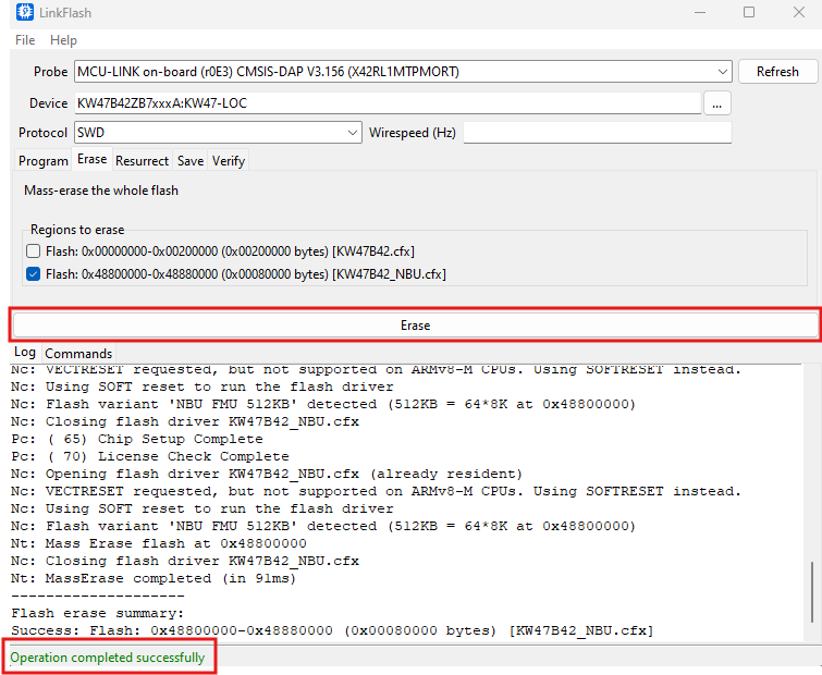
- Click the "Erase" button, then verify that the operation was successful by the message at the bottom of the window
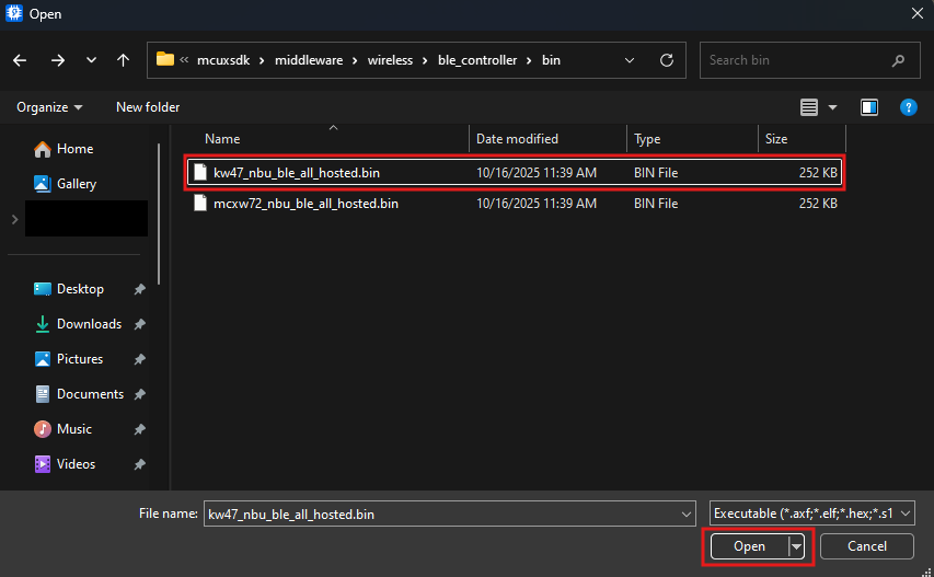
- Go back to the "Program" tab, and then click the "Browse" button to look for your NBU firmware binary file
- Access the directory where you installed your SDK for Section 2.2, follow the path to the NBU file:
"
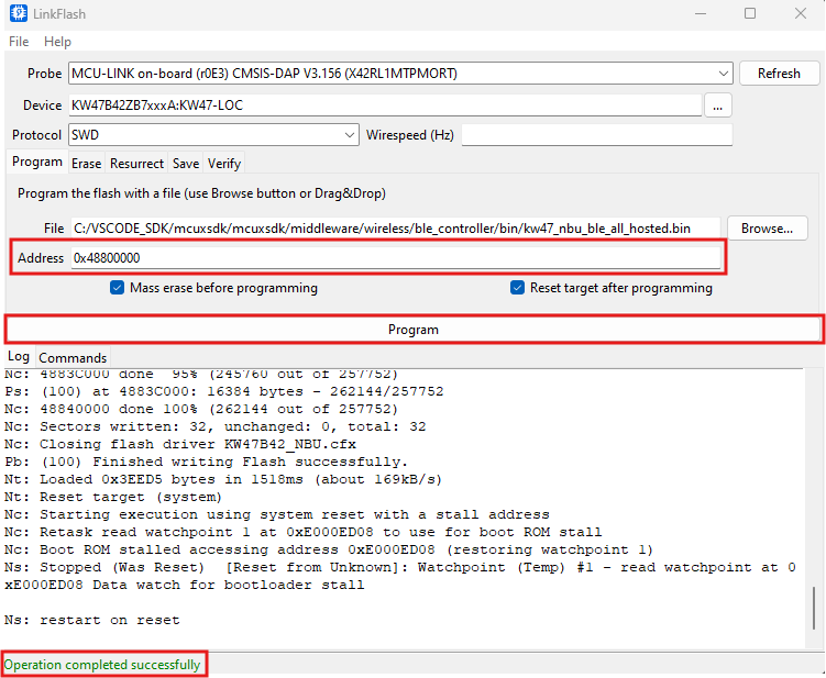
{your_SDK_path}\mcuxsdk\middleware\wireless\ble_controller\bin\kw47_nbu_ble_all_hosted.bin", then click "Open" - In the "Address" field, type
0x48800000, then click "Program" (verify the correct completion of the operation)
3.2 Build and Flash Application using MCUXpresso for VS Code
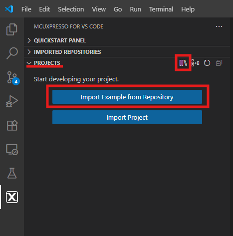
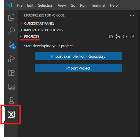
- Find the activity bar in the left-hand bar and click it to open it, then once it's open, go to the explorer and open the "PROJECTS" tab
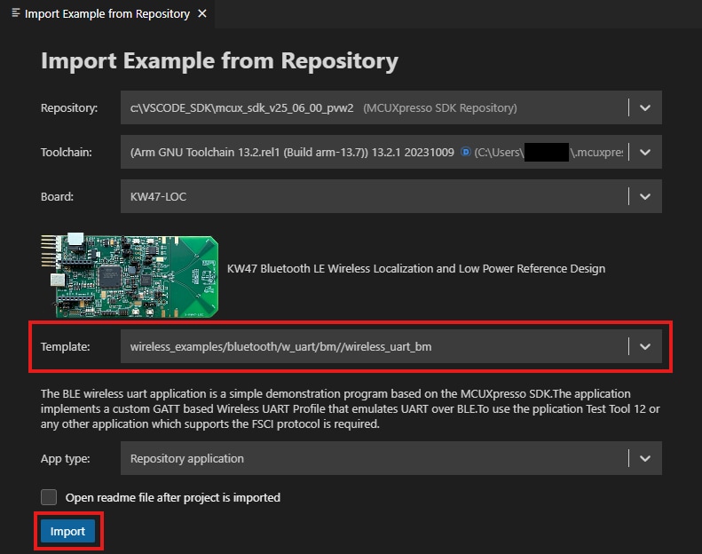
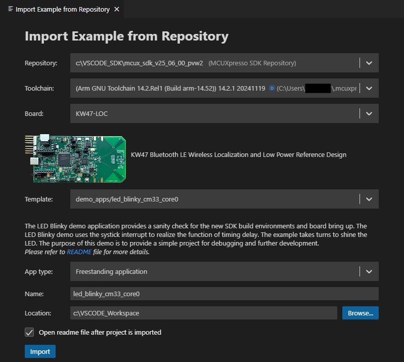
- Then click Import Example from Repository
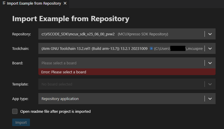
 The following tab will open in the editor screen
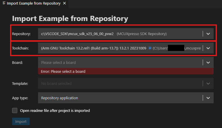
- Click the arrow button on the "Repository" tab to choose your previously downloaded SDK and the toolchain that matches the version
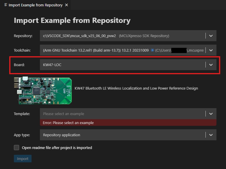
- Select the KW47-LOC board from the "Boards" drop-down menu
- Use the arrow button to expand the "Template" tab, select
the"
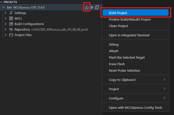
wireless_examples/bluetooth/bm/wireless_uart_bm" to use it as a template for the project, then click "Import" button - Select the project and build it by either clicking the "build" icon in the shortcuts provided or by right-clicking to select the "Build" option
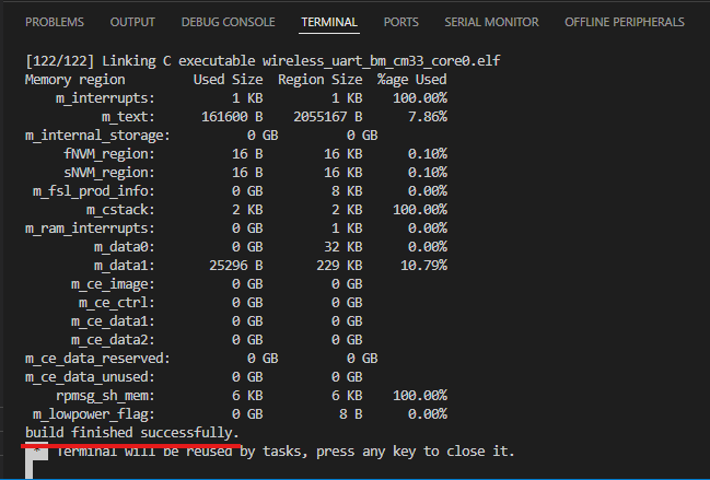
- The project should now build without any errors or warnings in the console
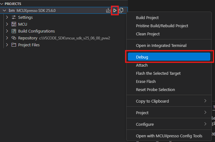
- Connect the board to your computer using the micro-USB to the
J3connector "MCU-LINK" port - Download the application to your board by either clicking the "debug" icon or by right-clicking to select the "Debug" option
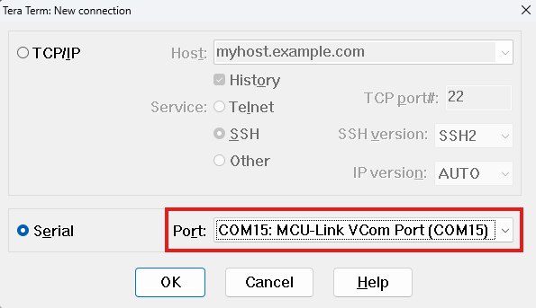
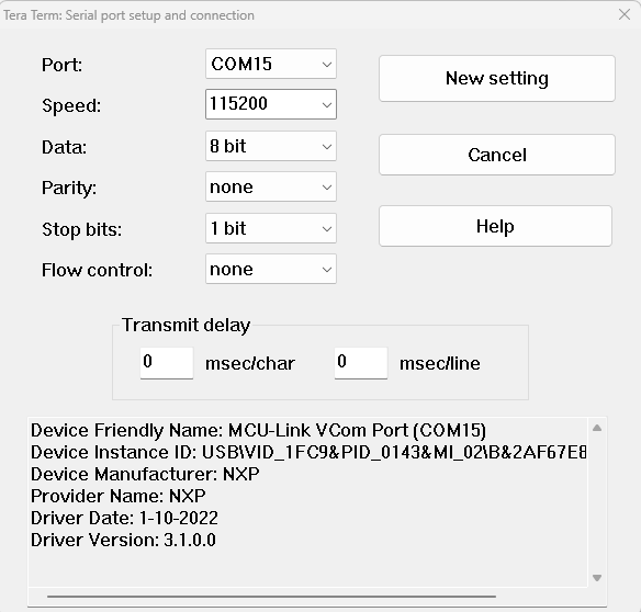
- Open up the serial terminal to view the application’s output, then select the port associated with the MCULINK
probe in your board's “
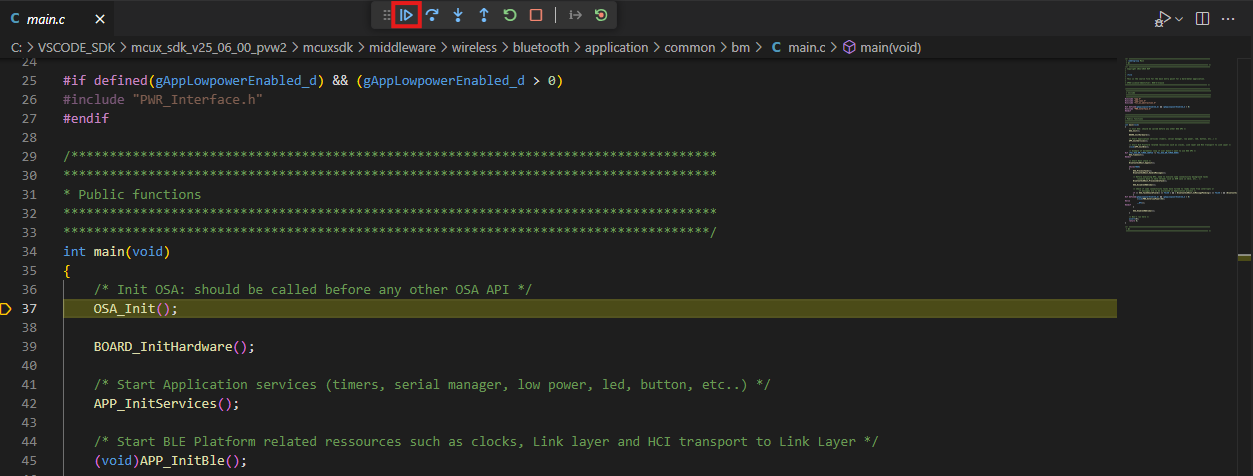
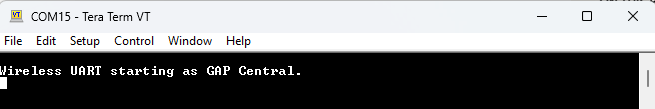
MCULink-VCOM” window (set your terminal to baud rate or speed to "115200", 8 data bits, no parity and 1 stop bit, then connect to that port) - Run the application by pressing the “run” icon (see the output printed on the terminal)
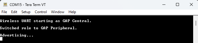
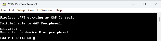
- Press
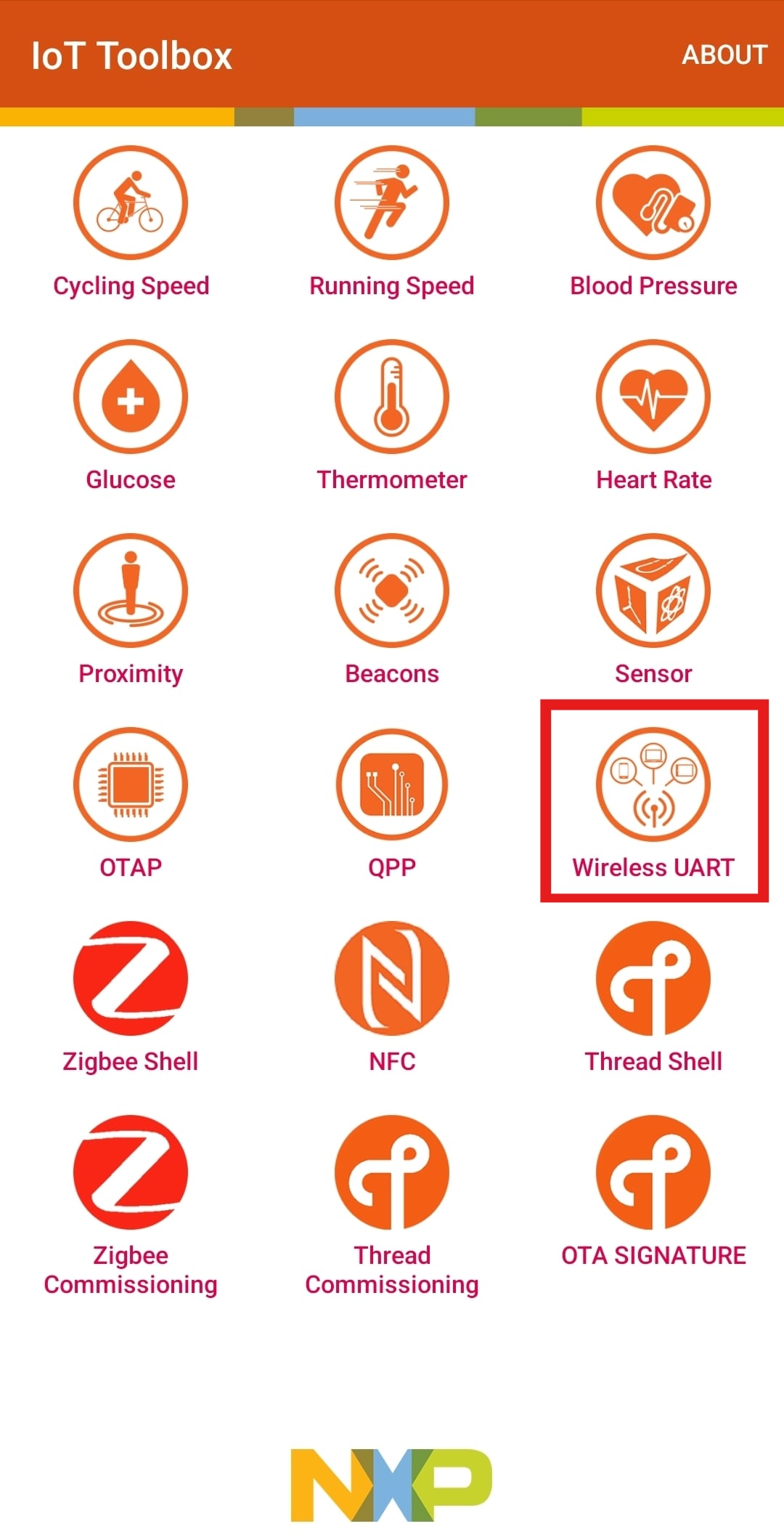
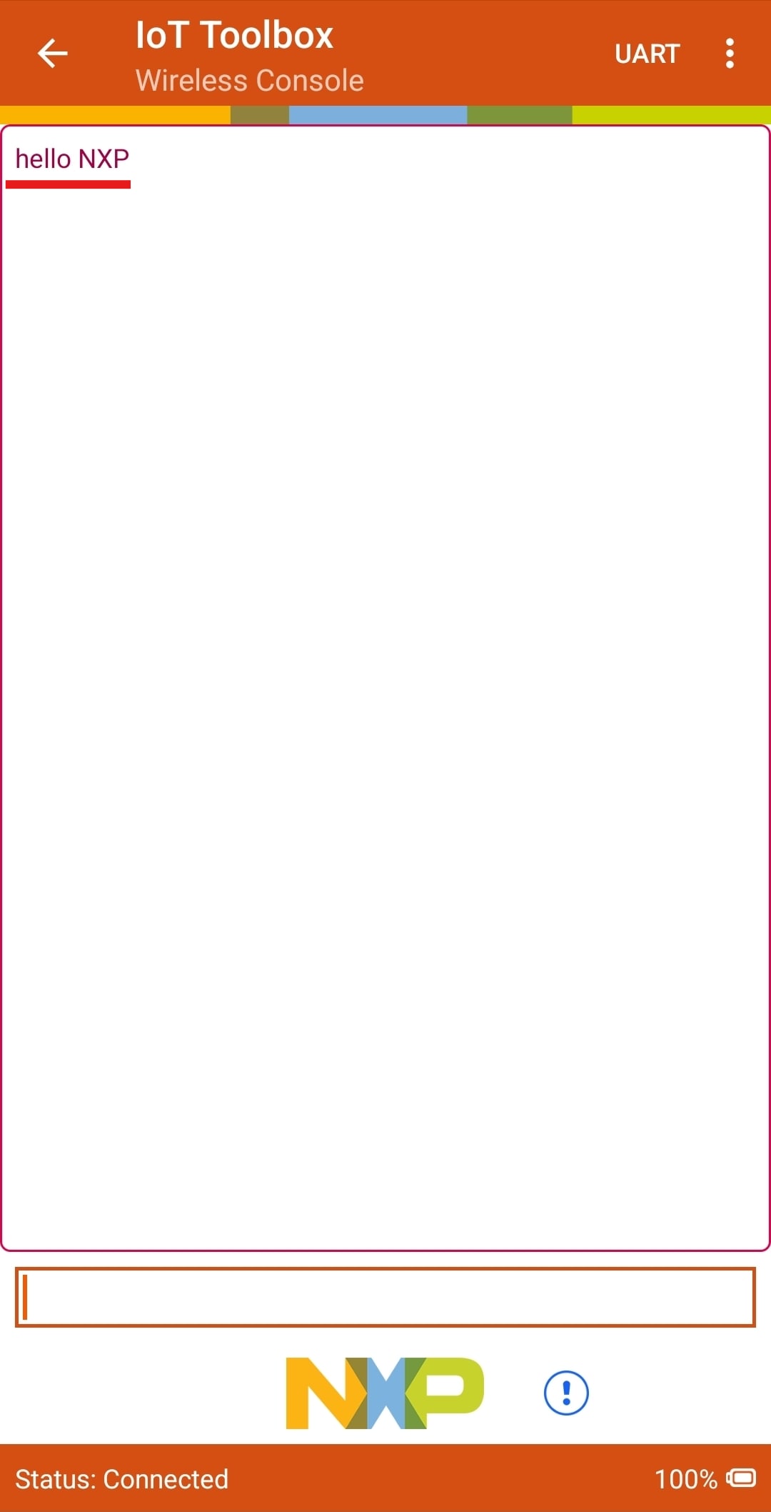
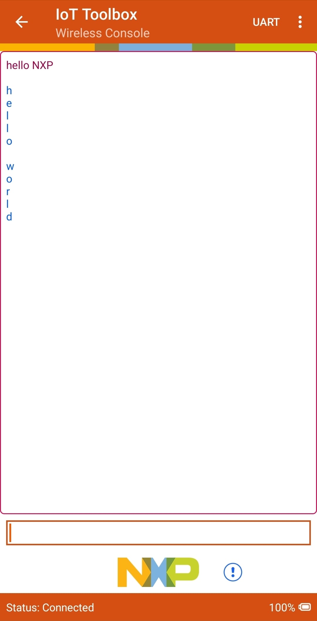
SW3button to switch the Bluetooth® Low Energy (BLE) role to peripheral, then pressSW2to start BLE Advertising (you should see the messages printed on the terminal) - Use the IoT Toolbox app to connect to the board by first selecting "Wireless UART" in the main menu
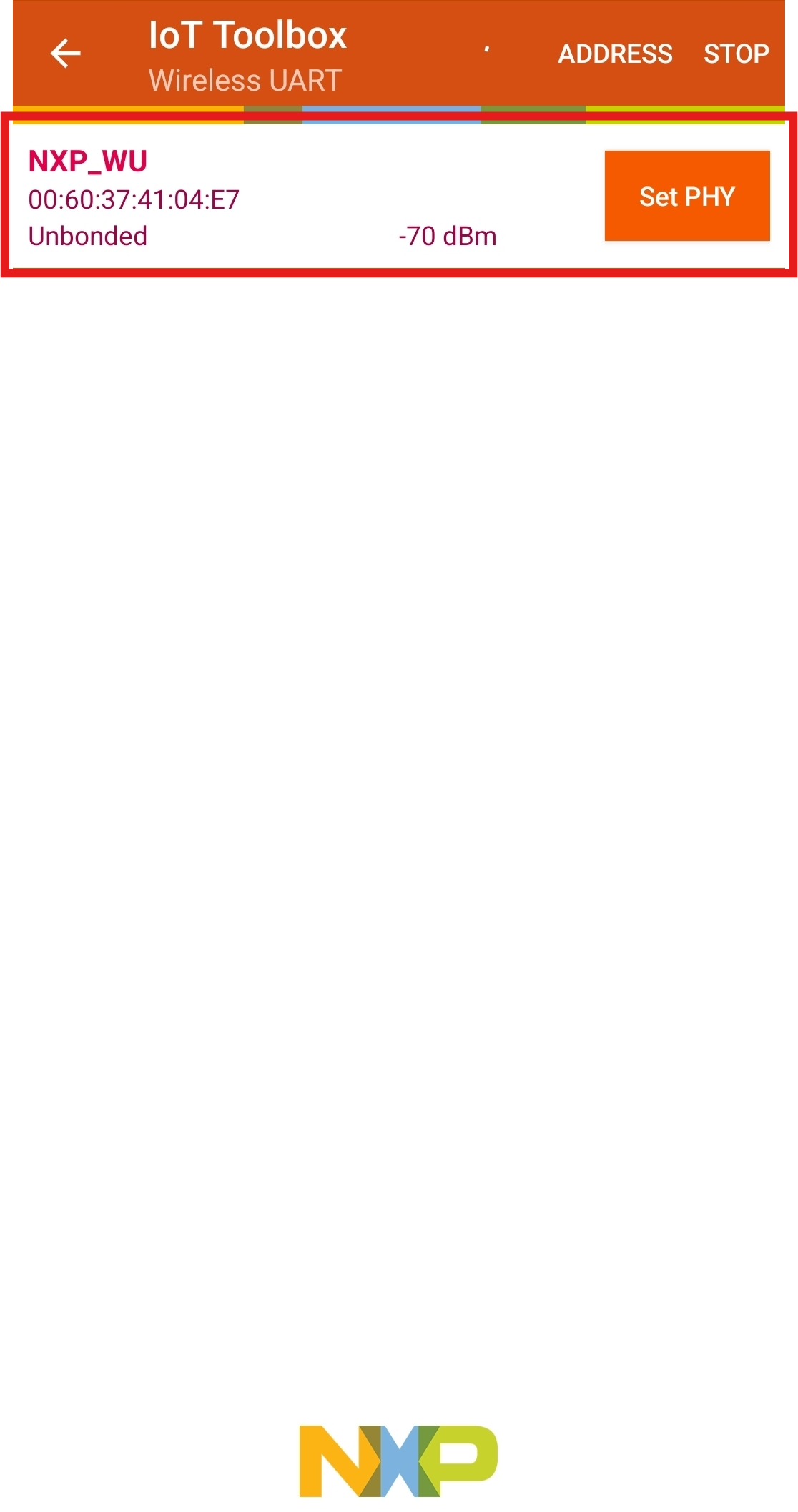
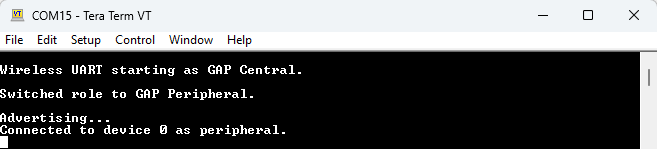
- Select the board to connect (you should see a connection message displayed on the terminal)
- Type any message into the app to see it appear in the serial terminal
- Type a message into the terminal to see it appear in the app
4. Create
4.1 Clone an Example Project from MCUXpresso for VS Code
The following steps will guide you through the manipulation of the general-purpose outputs (GPOs). In this example, the LED is set up to toggle every second.
- Following the instructions from the previous section, import the
led_blinkySDK example - Click on the “
led_blinky_cm33_core0” project in the "Name" field of the "Import Example from Repository" window to build, compile and run the demo as described in the previous section - You should now see the BLUE LED toggling each second
- You may now terminate the debug session
4.2 Use MCUXpresso Config Tools
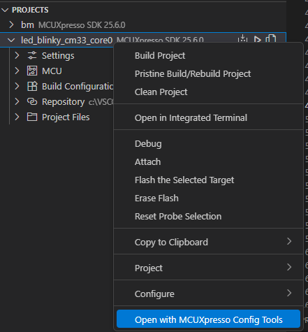
- Open the pins tool by right‑clicking on your project, then select "Open with MCUXpresso Config Tools"
- Select the "Open an existing configuration" option, navigate to the path where you installed the SDK, then to
mcuxsdk\examples\_boards\kw47loc\demo_apps\led_blinky\, selectled_blinky.mexfile and click on "Finish" - The pins tool should now display the pin configuration for the blinky led project
4.3 Use the Pins Tools to Modify the LED Routed Pin
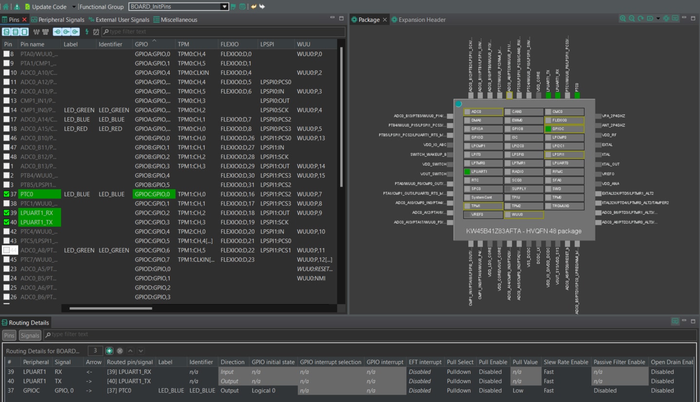
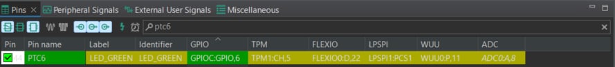
- In the Pins view, deselect the “Show dedicated pins” and “Show no routed pins” checkboxes so that only the routed pins are shown (indicated with a a green box next to the pin name and the functions selected for each routed pin are highlighted in green)
- For the current configuration,
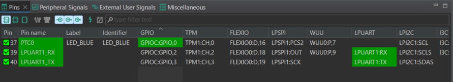
PTC0(LEB_BLUE) is routed as an output, so you will add the pin configuration to enable the GREEN LED - Select “Show no routed pins” to see the other options, enable the GREEN LED by searching for
PTC6, then selectGPIO6under the general-purpose input/output (GPIO) column (select "No" for any simultaneous routing message) - Next, configure the
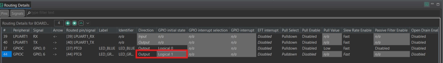
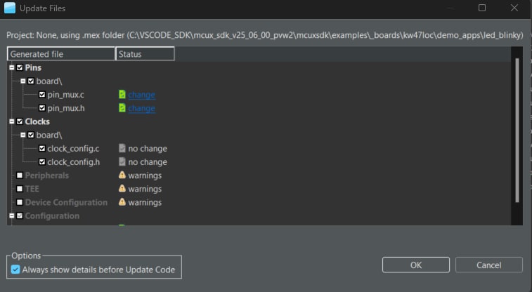
GPIOpin as an output and Logical 1 asGPIOinitial state in the “Routing Details” window - Now it’s time to implement these changes within the project by exporting the new updated
pin_mux.candpin_mux.hfiles that are generated by the Pins tool, so you will click on "Update Code" in the menu bar - The screen that pops up will show the files that are to be changed, so then you will click “OK” to overwrite the new files into your project
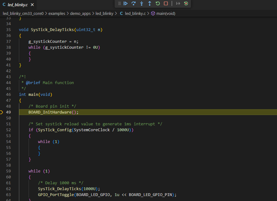
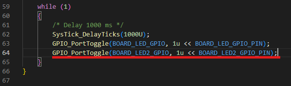
- Next, you will add some additional code to the example by opening
led_blinky.cfile and adding the following line to toggle the GREEN LED - Build and download the project per instruction in the previous section
- Run the application (you should now see the Green and Blue LED blinking alternately)
- Terminate the debug session

5. MCUXpresso Developer Experience
Check out each of the following sections to learn about the ecosystem provided for flexible protyping and development. The video below will introduce you to the FRDM platform, the full-featured EVK and the compatible shields for extended capabilities. In addition we will walk you through our Application Code Hub (ACH) portal where numerous application examples are provided through NXP's GitHub.
5.1 FRDM Platform, Full Feature EVK and Shields
For quick prototyping platforms, you have the option of low-cost FRDM platform or the full-featured EVK.
FRDM development boards come with standard form factor and headers, easy access to MCU I/Os, on-board MCU-Link debugger and a USB-C cable. Our full-featured evaluation kits include extended I/O and interface access, extendibility with Wi-Fi and additional MCU-Link features. There are also many compatible Click Boards and/or Arduino shields. For devices supported by an Open CMSIS Pack examples may be available on ACH. If not, many of them are easy to use via serial interface like inter-integrated circuit (I²C), serial peripheral interface (SPI), and universal asynchronous receiver/transmitter (UART), for which we provide drivers with examples in the MCUXpresso SDK.
5.2 Application Code Hub
The ACH further enhances our MCUXpresso Developer Experience by giving you an interactive dashboard to quickly locate software. Visit the ACH today to start exploring or discover additional details and benefits of the new interactive Application Code Hub.
Software in the ACH is located in NXP’s GitHub repository so it can be easily accessed and cloned from that location directly.
5.3 Demo Walkthrough
The following demo walks us through importing a project from ACH using a system based on the FRDM platform with a motor control shield and a low-cost LCD. Although your evaluation board may differ from this system, the following steps can be applied to all supported platforms.
Design Resources
Support
Forums
On this page
- 2.1
Install Your Toolchain
- 2.2
Jump Start Your Design with the MCUXpresso SDK
- 2.3
MCUXpresso Config Tools
- 2.4
Programming and Provisioning Tools
- 2.5
Installing IoT Toolbox