Getting Started with the KITFS5600SKTEVM Evaluation Board
Contents of this document
-
Get Started
-
Get Hardware
-
Install Software
-
Configure Hardware
Sign in to save your progress. Don't have an account? Create one.
Purchase your KITFS5600SKTEVM FS56 Socketed Board
1. Get Started
NXP analog product development boards provide an easy-to-use platform for evaluating NXP products. The boards support a range of analog, mixed-signal and power solutions. They incorporate monolithic integrated circuits and system-in-package devices that use proven high-volume technology. NXP products offer longer battery life, a smaller form factor, reduced component counts, lower cost, and improved performance in powering state-of-the-art systems.
This page will guide you through the process of setting up and using the KITFS5600SKTEVM evaluation board.
1.1 Kit Contents and Packing List
The KITFS5600SKTEVM contents include:
- Assembled and tested evaluation board in an anti-static bag
- FRDM-K82F FRDM Development Platform
- Unprogrammed QM, ASIL B and enhanced ASIL B FS5600 samples
- Quick Start Guide
1.2 Additional Hardware
In addition to the kit contents, the following hardware is necessary or beneficial when working with this kit.
- Power supply with a range up to 40 V
- Oscilloscope
- Voltmeter
1.3 Windows PC Workstation
This evaluation board requires a Windows PC workstation. Meeting these minimum specifications should produce great results when working with this evaluation board.
- USB-enabled computer with Windows 7 or Windows 10
1.4 Software
Installing software is necessary to work with this evaluation board. All listed software is available on the evaluation board's information page at KITFS5600SKT-EVM.
Refer to the user manual under Design Resources for additional details on featured component and board configurations.
2. Get Hardware
2.1 Board Features
- VBAT power supply connectors
- SW1 output capability up to 100 mA (internal MOSFET) - load current limited due to socket
- SW2 output capability up to 100 mA (external MOSFET) - load current limited due to socket
- EN1/2 switches
- PGOOD1/2 status indicators
- FS0B external safety pin
- LEDs that indicate signal or regulator status
- Emulation mode capabilities
- USB connection and GUI for register access, OTP emulation and programming
2.2 Board Description
The KITFS5600SKTEVM is a hardware evaluation tool that allows performance test and OTP programming of the FS5600.
An Emulation mode is possible to test different OTP configurations as needed. Different inductors and MOSFETs are included in the kit to allow the user to try different switching frequencies.
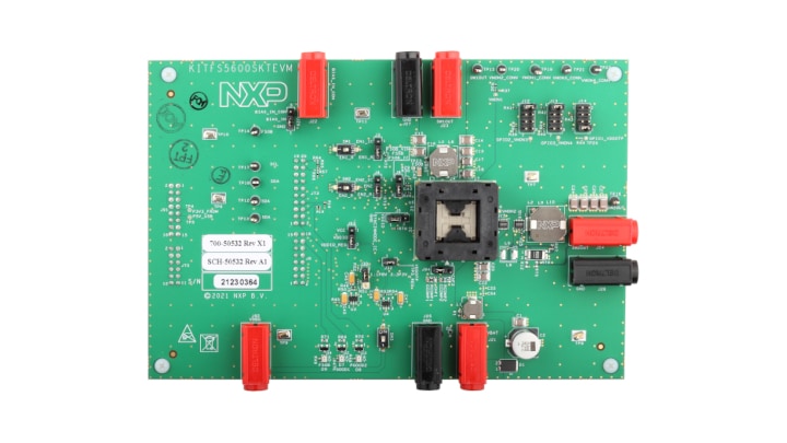
2.3 Board Components
Overview of the KITFS5600SKTEVM evaluation board KITFS5600SKTEVM.
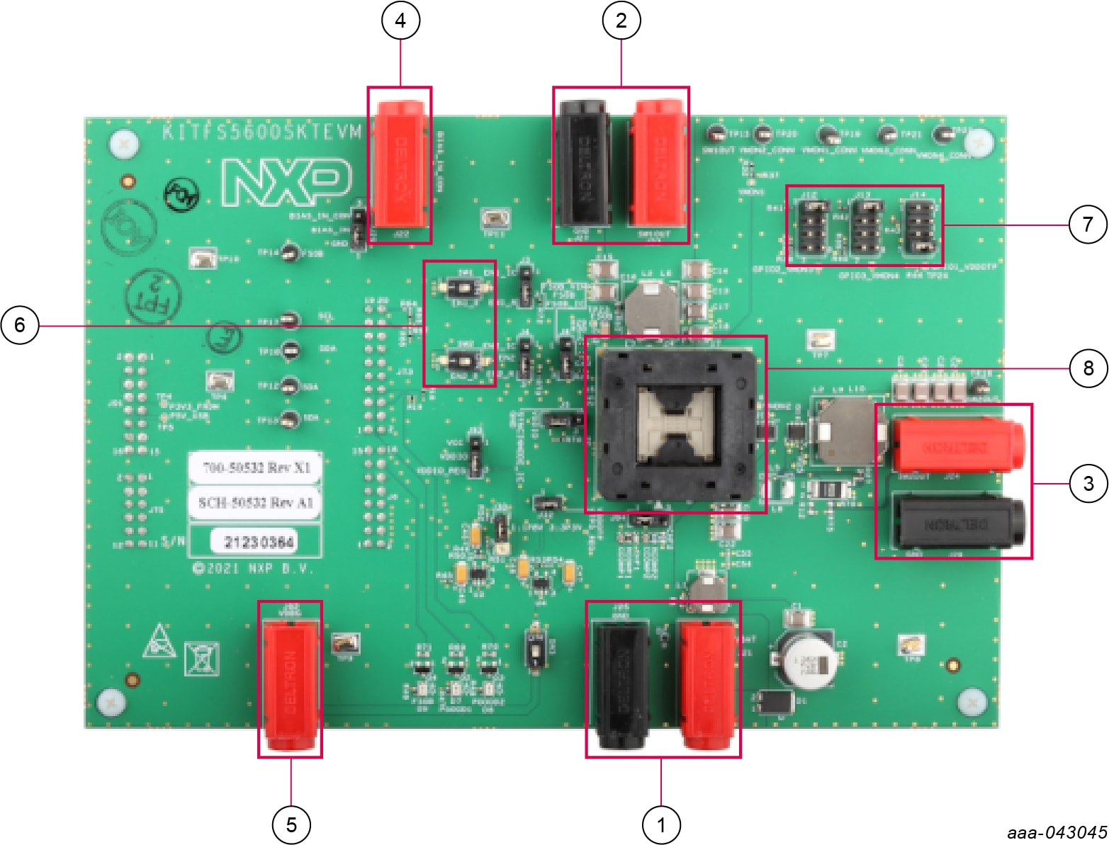
- VBAT connector
- SW1 output
- SW2 output
- BIAS_IN input
- Debug voltage input
- EN1 and EN2 switches
- GPIO1/2/3 option selection
- 32-pin QFN socket for inserting the FS5600
3. Install Software
3.1 GUI Installation
Unzip the NXPGUI_PR_x into any desired location. Find the NXP_GUI_x.x-Setup from the GUI folder inside the package and run it to install the GUI in any desired location.
3.2 FRDM Board Firmware Update
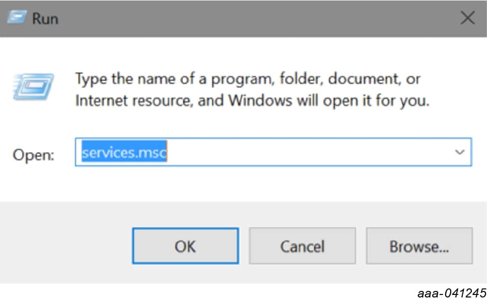
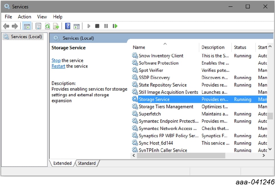
For Windows 10, disable the storage services: run services.msc; double-click on the storage service from the list and press the Stop button.
- Press the RST push button on the FRDM board and connect the USB cable into the SDA port (
J5) on the FRDM board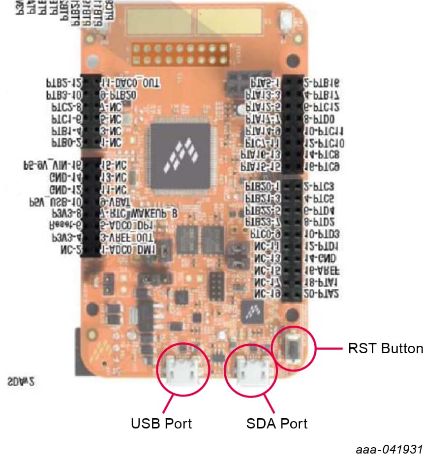
-
If a new “BOOTLOADER” device appears on the left pane of the File explorer:
- Drag and drop the downloaded file “0244_k20dx_bootloader_update_0x8000.bin” into the BOOTLOADER drive. Make sure to allow enough time for the firmware to be saved in the Bootloader
- Disconnect and reconnect the USB cable into the SDA port (this time WITHOUT pressing the RST push button)
- Drag and drop the file “k20dx_frdmk82f_if_crc_legacy_0x8000.bin” from the package (MCU folder) into the MAINTENANCE drive
- Skip 2a if MAINTENANCE appears in the File Explorer instead of BOOTLOADER. Follow 2b and 2c instead
- Locate the file “nxp-gui-fw-frdmk82f-usb_hid-fs5600_xxx.bin” from the package (MCU folder) and drag and drop the file into the FRDM_K82FD device
- FRDM board Firmware is successfully loaded. Disconnect and reconnect the USB cable into the USB port. Open the previously installed NXPGUI. The “Start” button on the top-left corner must be activated
- If only the NXPGUI firmware needs to be updated, then start from step 4 above. The PC detects FRDM_K82FD
To use the hardware configuration:
- When EVMs are shipped, all DIP switches are preset to certain configurations. To change the setting, refer to UM11596
To use the software GUI configuration:
- Users should first download PTN944 GUI from the NXP website. Users are encouraged to first flash the LPCUSBSIO module with the latest firmware, which is located under the GUI package firmware directory. Refer to UM11596 for additional details
- Connect USB-2-I²C module to a PC (via a micro USB cable) and EVM's
J5(via an included 10-pin ribbon cable) - In the GUI package, there is a directory "PTN3944 PCIe" to be used with PTN3944EVM-KIT. When GUI is executed, several default script files that are already pre-loaded in this directory for quick configuration. User can also go through each PTN3944's registers and change the channel equalizer settings manually
4. Configure Hardware
4.1 Configure Hardware
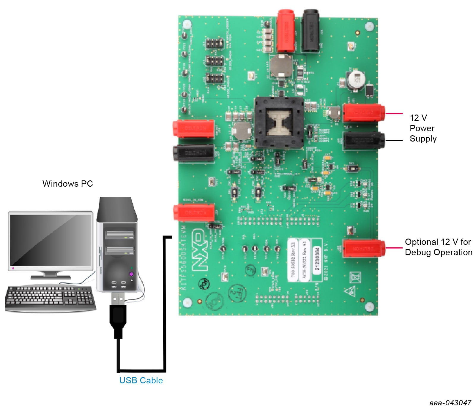
To configure the hardware and workstation as illustrated in Figure 1, complete the following procedure:
- Ensure that jumpers are in the default positions.
- With the USB cable connected to the PC and the USB port in the FRDM board K82F, apply power to the evaluation board by applying 12 V between
J21andJ25 - Press Reset on the FRDM board to make sure that the board is recognized
- Run the installed NXPGUI application from the Start menu or the installation folder
- A configuration window is displayed. Select the kit type and the device silicon version, and then click OK
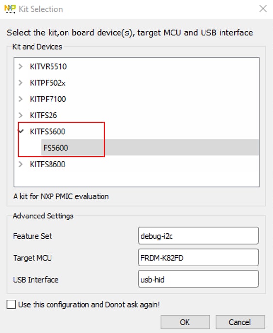
- Click Start to enable the connection to the device. Once the device is connected properly, the “Start” button is activated and the system is ready for operation


- If the NXPGUI does not recognize the FRDM-K82F board or if the Start button does not get activated, then it is possible that the interface is broken. In this case, reprogramming of the FRDM board can be attempted
Design Resources
Get Help
Forums
Connect with other engineers and get expert advice on designing with the KITFS5600SKT Evaluation Board on one of our community sites.