Power Management IC Test Guides
Contents of this document
-
Get started
-
Get to know the hardware
-
Install software
-
Configure the hardware
Sign in to save your progress. Don't have an account? Create one.
Purchase your PCA9450
Get started
The NXP analog product development boards provide an easy-to-use platform for evaluating NXP products. The boards support a range of analog, mixed-signal and power solutions. They incorporate monolithic integrated circuits and system-in-package devices that use proven high-volume technology. NXP products offer longer battery life, a smaller form factor, reduced component counts, lower cost and improved performance in powering state-of-the-art systems.
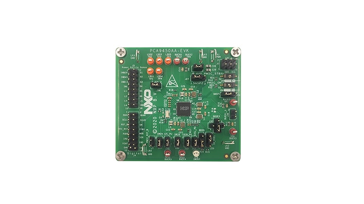
This page will guide you through the process of setting up and using the PCA9450AAEVK evaluation board.
1.1 Kit contents/packing list
The PCA9450AA-EVK contents include:
- Assembled and tested evaluation board in an anti-static bag
- Cable, USB 2.0 to MPSSE, 30 Mbps, 10 Pole, 0.5M, 3.3 V
- Quick start guide
1.2 Minimum System Requirements
There are three evaluation boards for the PCA9450 family device: PCA9450AA-EVK, PCA9450B-EVK and PCA9450C-EVK.
- 1x PCA9450 evaluation board, which allows easy evaluation on function and features
- 1x Interface (FTDI C232HM-EDHSL-0) cable, serves as a USB to I2C-bus interface between the computer and the PCA9450 evaluation board
- A Windows-based Graphic User Interface (GUI) provides a user-friendly interface to program on-chip I2C registers to exercise the feature on PCA9450
Get to know the hardware
2.1 Board features
- Six high-efficiency step-down regulators
- PCA9450AA – Three 3 A buck regulators
- PCA9450B – Two 3 A buck regulators
- PCA9450C – 6 A dual-phase buck regulator and 3 A buck regulator
- One 3.0 A buck regulator
- Two 2.0 A buck regulators
- Five linear regulators
- Two 10 mA LDOs
- One 150 mA LDO
- One 200 mA LDO
- One 300 mA LDO
- Support various memory types: DDR4/LPDDR4/DDR3L via system UBOOT configuration, no hardware change required
- 400 mA load switch with active discharge
- 32.768 kHz crystal oscillator buffer output
- 2-channel level translator
- Power control IOs
- Power ON/OFF control
- Standby/run mode control
- Fm+ 1 MHz I2C-bus interface
- ESD protection
- Human Body Model (HBM): +/- 2000 V
- Charged Device Model (CDM): +/-500 V
- 7 mm x 7 mm, 56 pin HVQFN with 0.4 mm pitch
2.2 Board Description
PCA9450AA-EVK, PCA9450B-EVK, and PCA9450C-EVK boards provide flexibility to play with all the features of PCA9450AA, PCA9450B and PCA9450C PMIC devices and make measurements on the devices. I2C interface in the board supports the communication between PCA9450 devices and GUI in PC platform through FTDI C232HM-EDHSL-0 cable.
The board is designed for evaluating PCA9450AA, PCA9450B and PCA9450C PMIC devices.
Install software
- Unzip the provided PCA9450 Evaluation Kit GUI file into selected folder. If password is asked during unzip, type “NXP”
- Install the FTDI cable driver from website D2XX Drivers
- Run the file PCA9450.exe
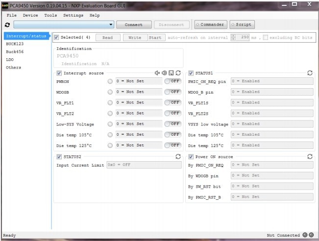
3.1 Additional Software Support
Refer to UM11556 , PCA9450AA-EVK evaluation board for additional software details.
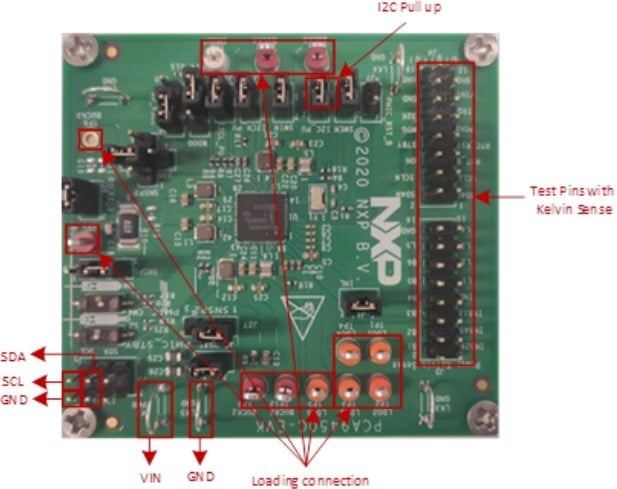
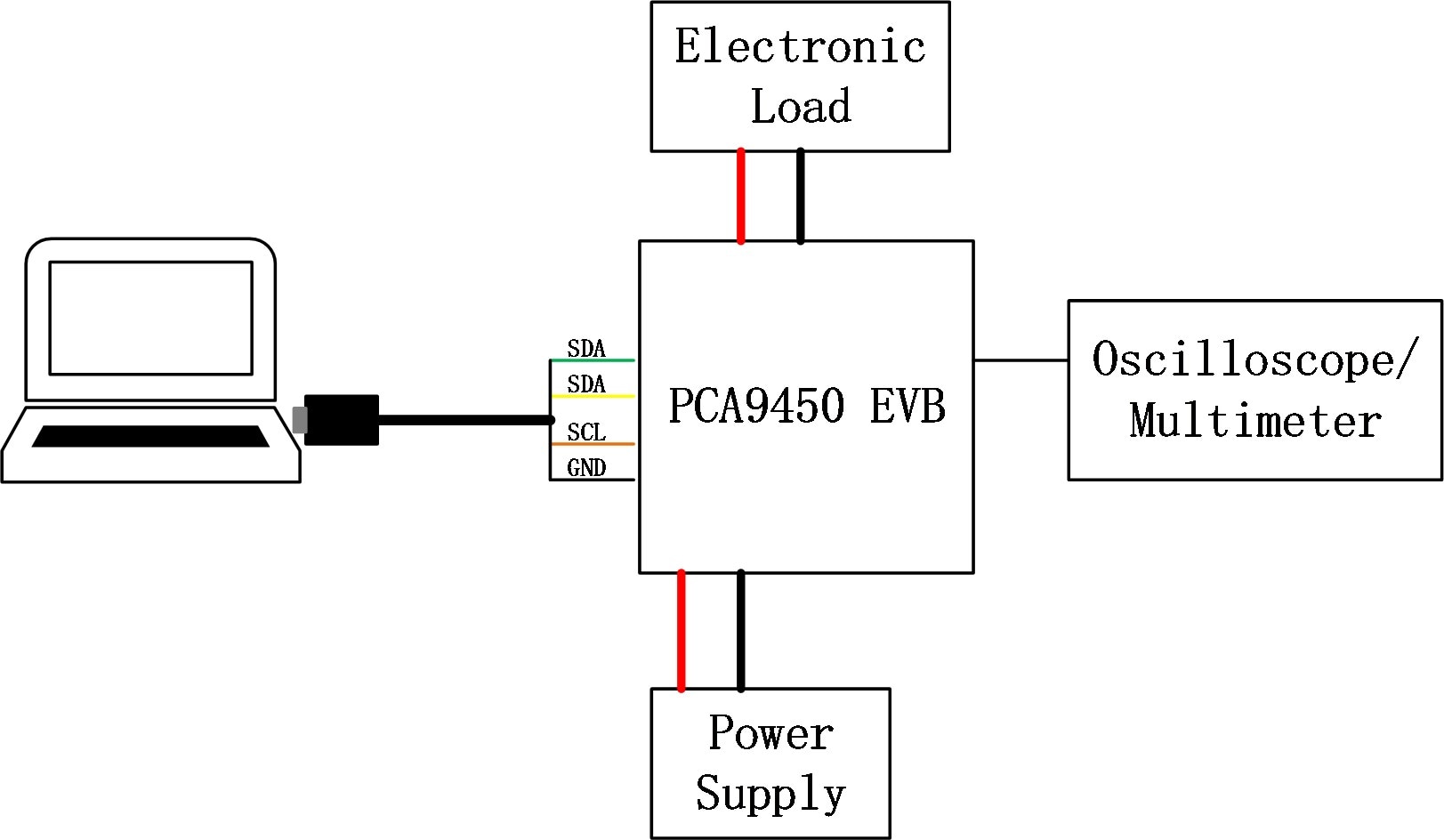
Configure the hardware
Suggested equipment needed for test:
- PC/laptop with Windows 7 / Windows 10 OS
- Power supply (5.0 V typical)
- Electronic load
- Oscilloscope/multimeter
- FTDI cable C232HM-DDHSL-0
- Connect the jumper and switches (refer to schematics for default settings)
- Connect the board to power supply (5.0 V) on Vin
- Connect the loading to the regulators
- Connect the board to GUI in PC through FTDI cable C232HM-DDHSL-0
- Turn On power supply (5.0 V) on Vin
- Turn On the loading
4.1 Additional Board Support
Refer to UM11556 , PCA9450AA-EVK evaluation board user manual for additional details on the hardware configuration.