Getting Started with the S32K148-T-BOX
Last Modified:
2019-06-24 15:16:06Supports
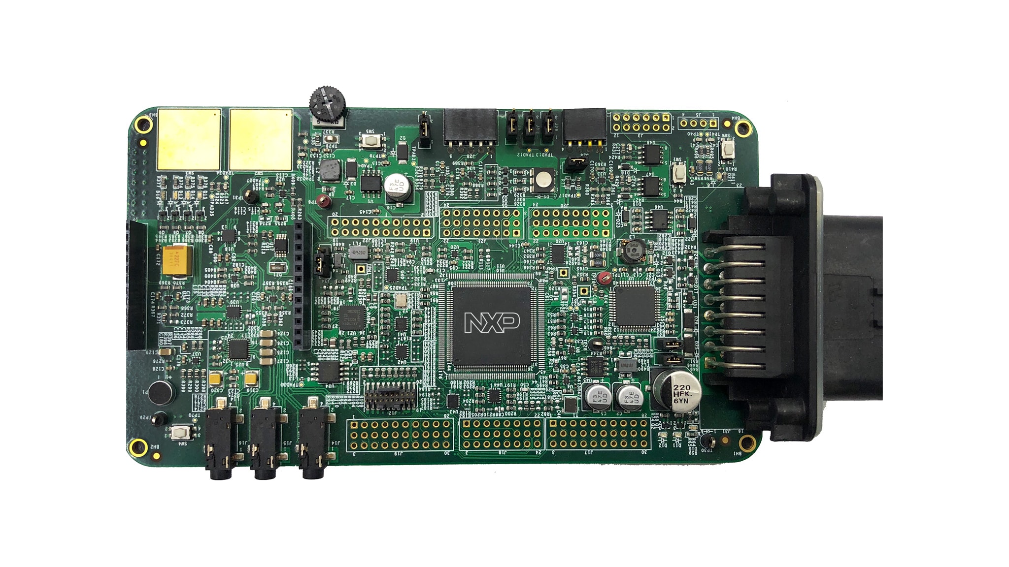
S32K148 Automotive Telematics Box (T-Box)
Contents of this document
-
Plug It In
-
Get Software
-
Configure Hardware
-
Build, Run
Sign in to save your progress. Don't have an account? Create one.
Purchase your S32K148 Automotive Telematics Box (T-Box)
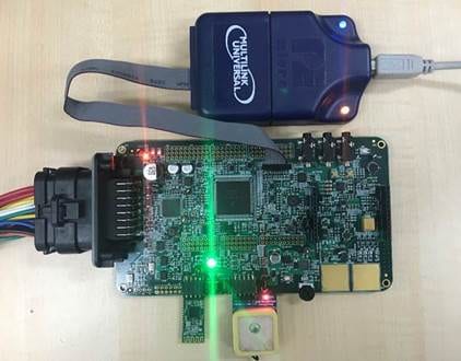
1. Plug It In
Let's take your S32K148-T-BOX for a test drive.
2. Get Software
2.1 Download the S32K148-T-BOX QSP
Download the S32K148-T-BOX Quick Support Package (QSP) including the S32K148_Based_T_BOX_BSP_TestPrj_SDK_RTM2_0.zip to kick start your design.
2.2 Get the S32 Design Studio for Arm
Download and Install the S32DS for Arm®
2.3 Get the S32K SDK RTM
Download and Install the S32 Design Studio for Arm 2018.R1 Update 6 SDK S32K14x RTM v.2.0.0 (REV UP6)
Download S32K SDK RTM3. Configure Hardware
3.1 Configure Hardware
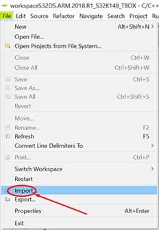
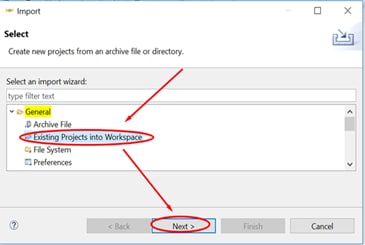
- Open S32DS for Arm IDE and select File → Import
- Then select General → Existing Projects into Workspace → Next
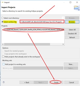
- Go to Select archive file → Browse option to choose the
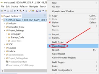
S32K148_Based_T_BOX_BSP_TestPrj_SDK_RTM2_0.zipfile and then select the project → Finish - After importing the project, clean it at first by selecting the project in the Project Explorer, then right-click and choose Clean Project
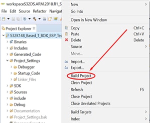
- Select the project in the Project Explorer, then right-click and choose Build Project
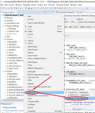
- Select the project in Project Explorer, then right-click, and choose Debug As → Debug Configuration
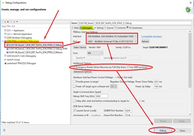
- In the Debug Configuration window, select the GDB PEMicro Interface Debugging → S32K148_Based_T_BOX_BSP_TestPrj_SDK_RTM2_0_Debug → Debugger
- Under Interface select right debugger and ensure Port has the right part number, then in Additional Options, check Emergency Kinetis Device Recovery by Full Chip Erase and Use SWD protocol (if not check this option, it will use JTAG debug protocol). Click Debug to launch the debug
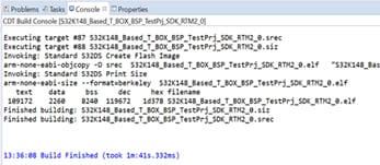
4. Build, Run
4.1 S32K148-T-BOX BSP Test Project
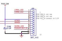
Use an USB-to-UART adapter to connect the board with PC via J25-6 (TXD), J25-7 (RXD) and J25-12 (GND)
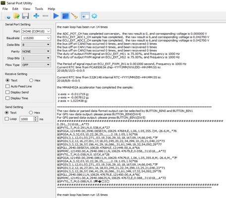
4.2 Configure the Serial Communication Format
Open a UART console (e.g. Serial Port Utility) on PC, configure its serial communication format:
- Datarate : 115200 baud/s
- Data Bits: 8
- Parity: None
- Stop Bits: 1
- Flow Control: OFF