Getting Started with the SJA1110-MGS-EVM
Contents of this document
-
Out of the Box
-
Get Hardware
-
Install Software
-
Configuring the Hardware
Sign in to save your progress. Don't have an account? Create one.
Purchase your SJA1110-MGS-EVM
1. Out of the Box
The NXP analog product development boards provide an easy-to-use platform for evaluating NXP products. The boards support a range of analog, mixed-signal and power solutions. They incorporate monolithic integrated circuits and system-in-package devices that use proven high-volume technology. NXP products offer longer battery life, a smaller form factor, reduced component counts, lower cost, and improved performance in powering state-of-the-art systems.
This page will guide you through the process of setting up and using the SJA1110-MGS-EVM board.
1.1 Kit Contents and Packing List
The kit contents include:
- Assembled and tested SJA1110-MGS-EVM evaluation board in an antistatic bag
- Twisted-pair cable with MATEnet connectors
- Quick start guide
1.2 Additional Hardware
In addition to the kit contents, the following hardware is needed when working with this board.
- A 12 V power supply that can deliver at least 1 A
- A PEmicro debugger
- A Windows PC and a USB cable
2. Get Hardware
The SJA1110-MGS-EVM board was designed to facilitate the testing and evaluation of SJA1110, TJA112x and TJA1104 product features.
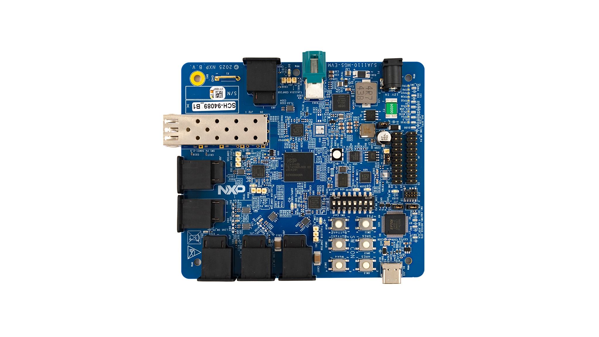
2.1 Board Overview
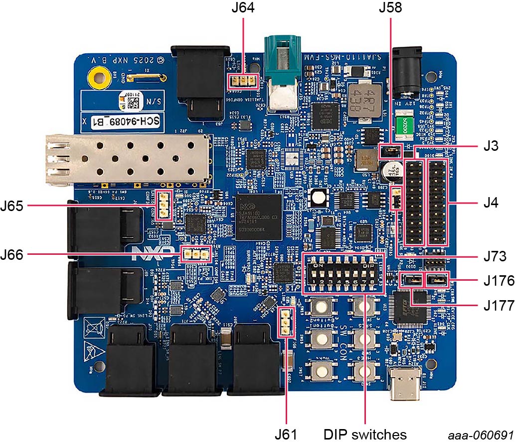
The main components and ports on the SJA1110-MGS-EVM are indicated and labeled in Figure 1. Jumpers and DIP switches are highlighted in Figure 2. Board dimensions are 105 mm x 118 mm.
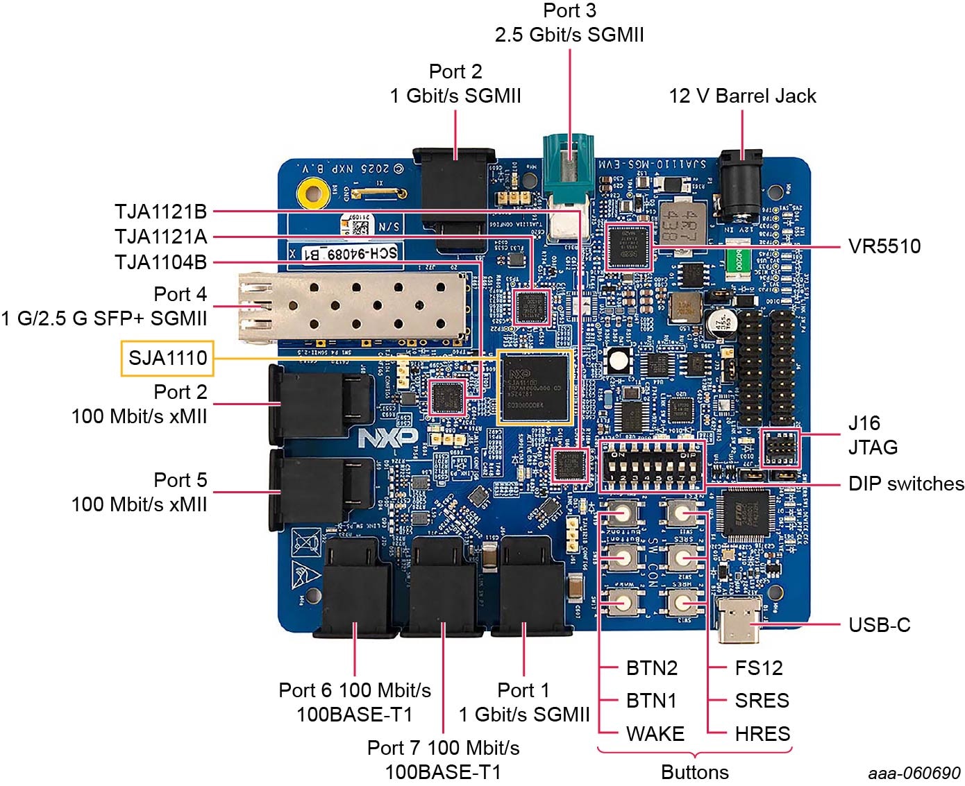
2.2 Board Features
- SJA1110D secure variant
- Power supply based on VR5510 PMIC using a single 12-volt input
-
Ethernet ports:
- 3x 100BASE-T1 (SJA1110 internal PHYs)
- 1x 100BASE-T1 Ethernet port using the TJA1104B automotive Ethernet PHY
- 2x 1000BASE-T1 Ethernet port using the TJA1121A/B automotive Ethernet PHY
- 1x SFP+ cage
- 1x 2.5G Ethernet port using the TJA1230 automotive Ethernet PHY (not available on Rev. 1.0 of the board)
- JTAG connector to access ARM core of SJA1110
- Several LEDs controlled by HW and SW displaying useful information
- Multiple DIP switches to change specific settings
- USB-C connector for SPI access
3. Install Software
3.1 Install Software
The following software can be downloaded from nxp.
-
Install S32 Design Studio
- Visit www.nxp.com and log in to your account
- Search for 'S32 Design Studio for S32 Platform' and download version 3.5
- Run the installer and follow the onscreen instructions
-
Download the minimum required real-time packages (RTP):
- Visit www.nxp.com and log into your account
- Select 'My NXP Account → Software Licensing and Support → View accounts → Automotive SW → SJA11XX Standard Software'
-
Select 'Automotive 'SW - SJA11XX - Real Time Drivers' and download the following two packages:
- SJA11XX_RTD_4.4_1.0.0_DS_Updatesite_D2302.zip
- SJA11XX_RTD_4.4_1.0.1_P02_D2410_DS_updatesite.zip
-
Select 'Automotive SW - SJA11XX - Ethernet Switch Real Time Drivers' and download the following package:
- SW32SJA1110_SJA11XX_ETH_SWITCH_4.4_1.0.1_DS_updatesite_D2411.zip
-
Select 'Automotive SW - SJA11XX - Ethernet PHY Real Time Drivers' and download the following package:
- SW32SJA1110_XJA11XX_ETH_PHY_4.4_1.0.7_DS_updatesite_D2412.zip
-
Download SJA1110-MGS-EVM example projects:
- Visit www.nxp.com/SJA1110-MGS-EVM, scroll down to the Software section and download the 'SJA1110 Software Examples':
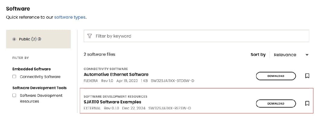
- Select 'SJA1110_Examples_4.4_0.1.0_D2504_DesignStudio_updatesite.zip' and install it in folder S32 Design Studio for S32 Platform 3.5
- Visit www.nxp.com/SJA1110-MGS-EVM, scroll down to the Software section and download the 'SJA1110 Software Examples':
-
Download additional RTD software packages based on specific use cases. These can also be downloaded from SJA11XX Standard Software and installed later
- FreeRTOS: SW32SJA11xx_FreeRTOS_11.1.0_0.8.0_CD2_D2411_DesignStudio_updatesite.zip
- gPTP: SW32SJA11xx_M7_gPTP_1_0_0_D2411_DesignStudio_updatesite.zip
- TCP/IP: SJA11XX_TCPIP_1_0_3_D2402_DS_updatesite.zip
-
Start S32 Design Studio and install all RTD packages:
- Help → Install New Software ... → Add → Archive
- Select the .zip file, click 'Add' and follow the instruction for the installer
4 Configuring the Hardware
4.1 Configuring the Hardware
After downloading available documentation (schematics, layout files and user manual) for the SJA1110-MGS-EVM, configure the hardware as follows:
- Check that jumper
J58is connected - For an initial setup, NXP recommends setting the DIP switches (SW2) as indicated in Table 1:
- Connect a power supply to the 12 V barrel jack to power the board. A 12 V power supply that can deliver at least 1 A is recommended to ensure reliable functionality
- Connect the PEmicro debugger to the JTAG connector
(J16)
| DIP switch | Position |
|---|---|
| SW2.1 | OFF |
| SW2.2 | ON |
| SW2.3 | OFF |
| SW2.4 | OFF |
| SW2.5 | OFF |
| SW2.6 | ON |
| SW2.7 | ON |
Flashing an Example Project
Flashing an Example Project
- Start S32 Design Studio for S32 Platform 3.5
- Select 'File → New → S32DS Project from Example' or use shortcut CTRL + ALT + E
- Select 'SJA11110 Examples AUTOSAR 4.4 x.x.x' and select the desired example project
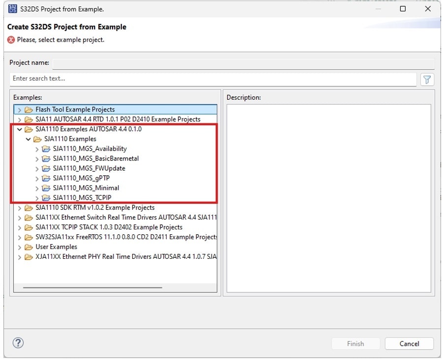
- Click 'Finish' to import the project into the workspace
- Double-click the
.mexfile in the project explorer to open the configuration tool: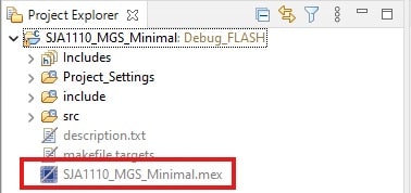
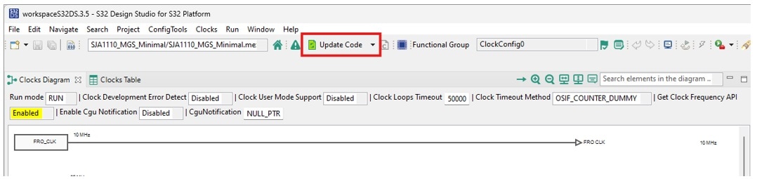
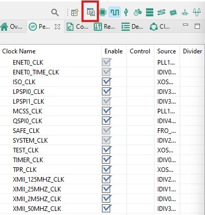
- Click 'Update code' to generate the code of the configuration:
- Go back to the code view by clicking on the C/C++ icon:
- Select 'Project” → “Build project' to compile the example project
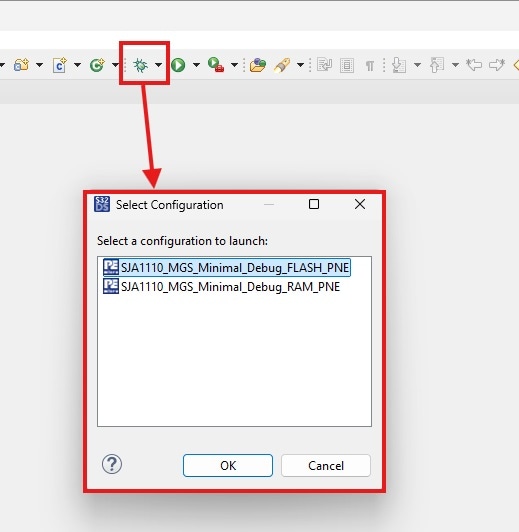
- Once the build is finished, select the 'Debug As …' icon and select either Debug FLASH or Debug RAM configuration and click 'OK':
- The example project will be flashed onto the SJA1110-MGS-EVM. Once finished, click 'Run' to start the Firmware
Design resources
Board Information
Available to selected customers only (nondisclosure agreement (NDA) required). Contact your local NXP sales representative for more information.