Getting Started with the TEA2093DB2202 Evaluation Board
Contents of this document
-
Get Started
-
Know the Board
-
Configure the Hardware
Sign in to save your progress. Don't have an account? Create one.
Purchase your TEA2093 Synchronous Rectification Evaluation Board
1. Get Started
This page will help guide you through the process of learning about your TEA2093 evaluation board.
1.1 Box Contents
- TEA2093DB2202 add-on board
1.2 Required Equipment
- AC mains source
- Power analyzer
- Electronic load
- Oscilloscope for observing operation behavior
- Current probe
- Differential probe (for high side SR)
1.3 Additional Hardware
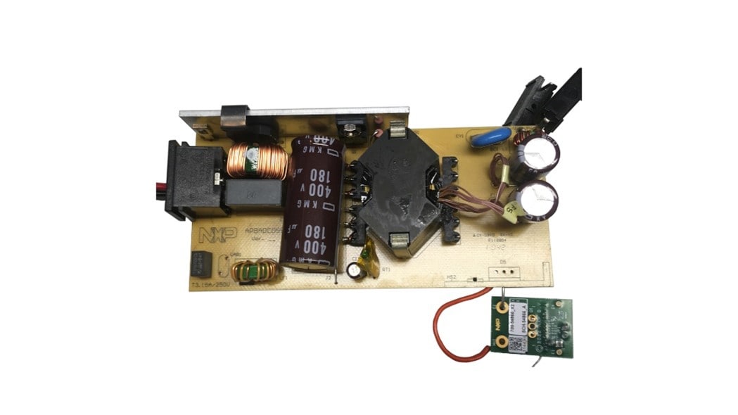
- An existing switch mode power supply board with an asymmetrical half bridge or standard flyback topology and a diode rectifier at the secondary side
2. Know the Board
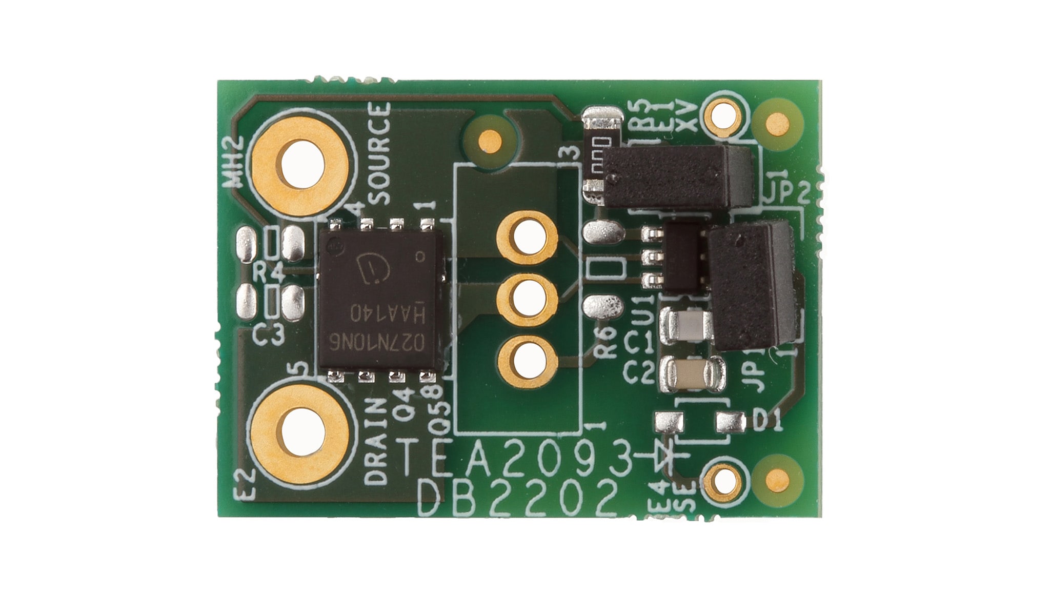
2.1 Know the Board
The TEA2093DB2202 evaluation board contains a TEA2093TS SR controller in a TSOP-6 package and a 100 V / 2.7 mΩ MOSFET in a TDSON-FL package. It replaces the secondary-side rectification part of an SMPS with an asymmetrical half bridge or standard flyback topology and can be placed at the low (ground) side as well as at the high side of the secondary transformer winding.
Additionally, the TEA2093DB2202 evaluation board contains an option to replace the mounted MOSFET by a MOSFET in a TO-220 package.
The TEA2093TS can generate its own supply voltage or operate with an external applied voltage. Both options can be configured through jumpers at the board.
3. Configure Hardware
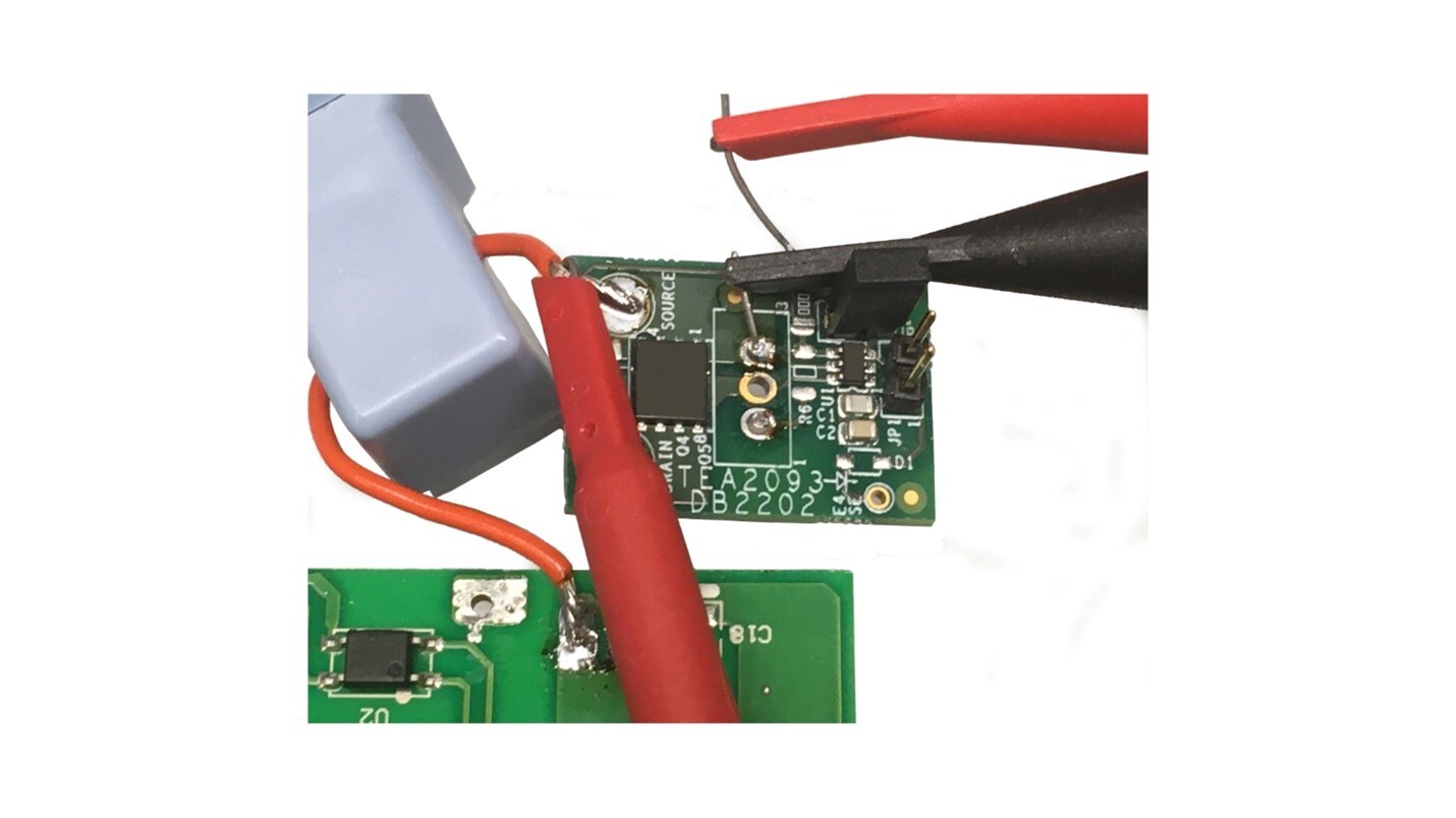
3.1 Connecting the Board to an Existing SMPS
Remove the secondary side rectifier diode from your switch mode power supply and solder the SOURCE to the anode connection and the DRAIN to the cathode connection of the diode. Configure the jumpers as described in section 7 of user manual UM11772.
3.2 Connecting the Oscilloscope
The operation of the TEA2093 in the power supply can be evaluated by measuring:
For high side connection
- The SOURCE connection
- The GATE to SOURCE signal with a differential probe
- The current through the MOSFET
For low (ground) side connection
- The DRAIN connection
- The GATE signal
- The current through the MOSFET
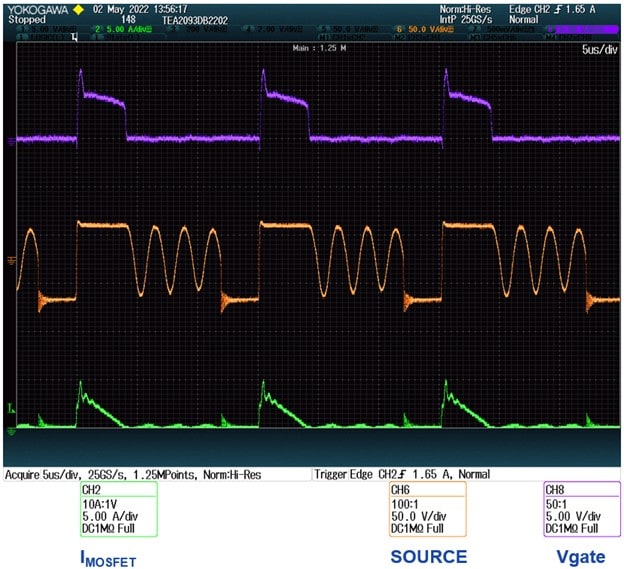
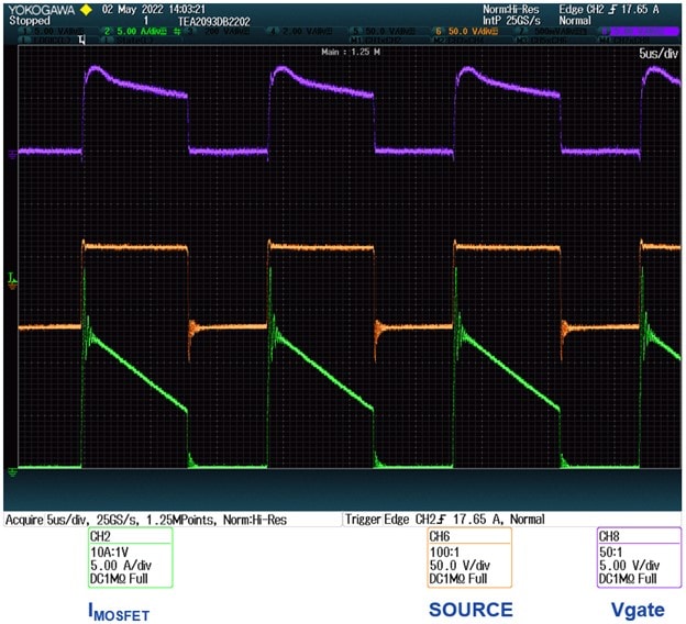
3.3 Oscilloscope Signals
Operation in continuous conduction mode in a flyback with high side rectification
Operation in quasi resonant mode in a flyback with high side rectification
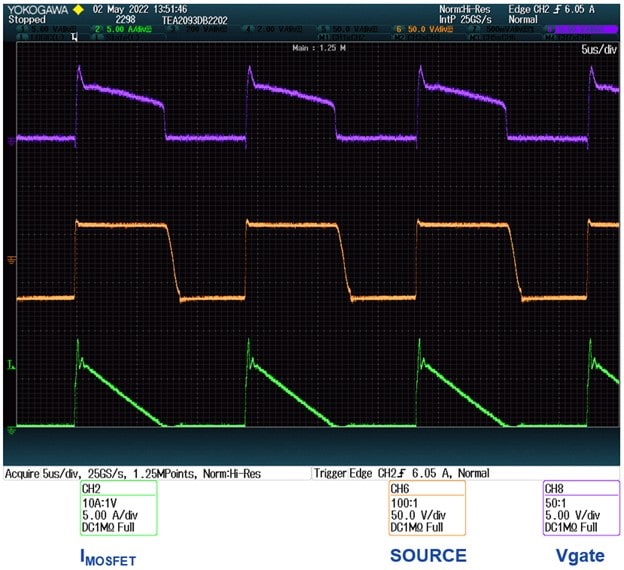
Operation in discontinuous mode in a flyback with high side rectification