- Analog Toolbox
- Getting Started with the TEA2376DK1011
Getting Started with the TEA2376DK1011
Contents of this document
-
Get Started
-
Get Hardware
-
Configure Hardware
Sign in to save your progress. Don't have an account? Create one.
Purchase your TEA2376DK1011
1. Get Started
The NXP analog product development boards provide an easy-to-use platform for evaluating NXP products. The boards support a range of analog, mixed-signal and power solutions. They incorporate monolithic integrated circuits and system-in-package devices that use proven high-volume technology. NXP products offer longer battery life, a smaller form factor, reduced component counts, lower cost and improved performance in powering state-of-the-art systems.
This page will guide you through the process of setting up and using the TEA2376DK1011 programming kit.
1.1 Kit Contents and Packing List
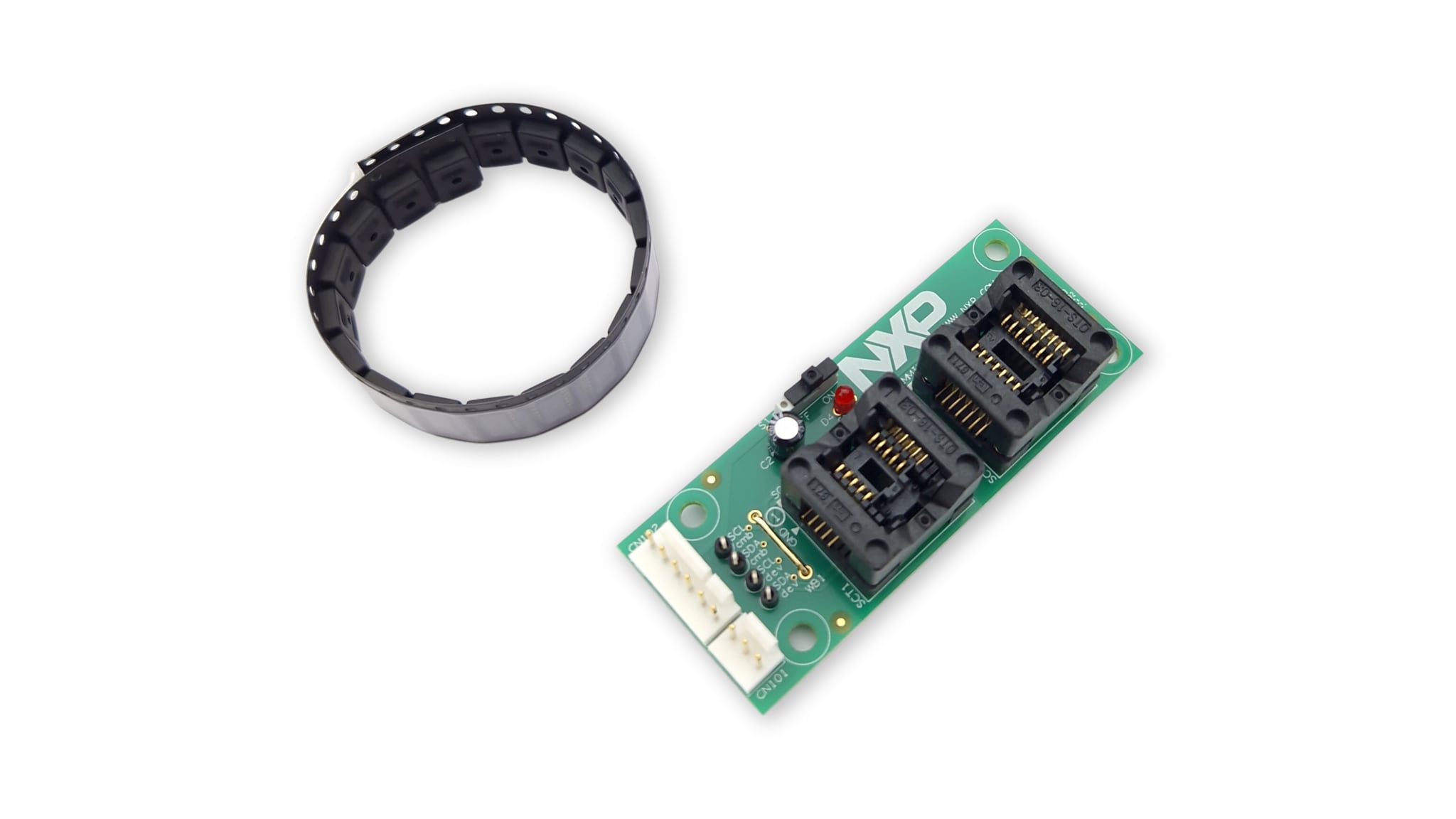
The contenst of the TEA2376DK1011 include:
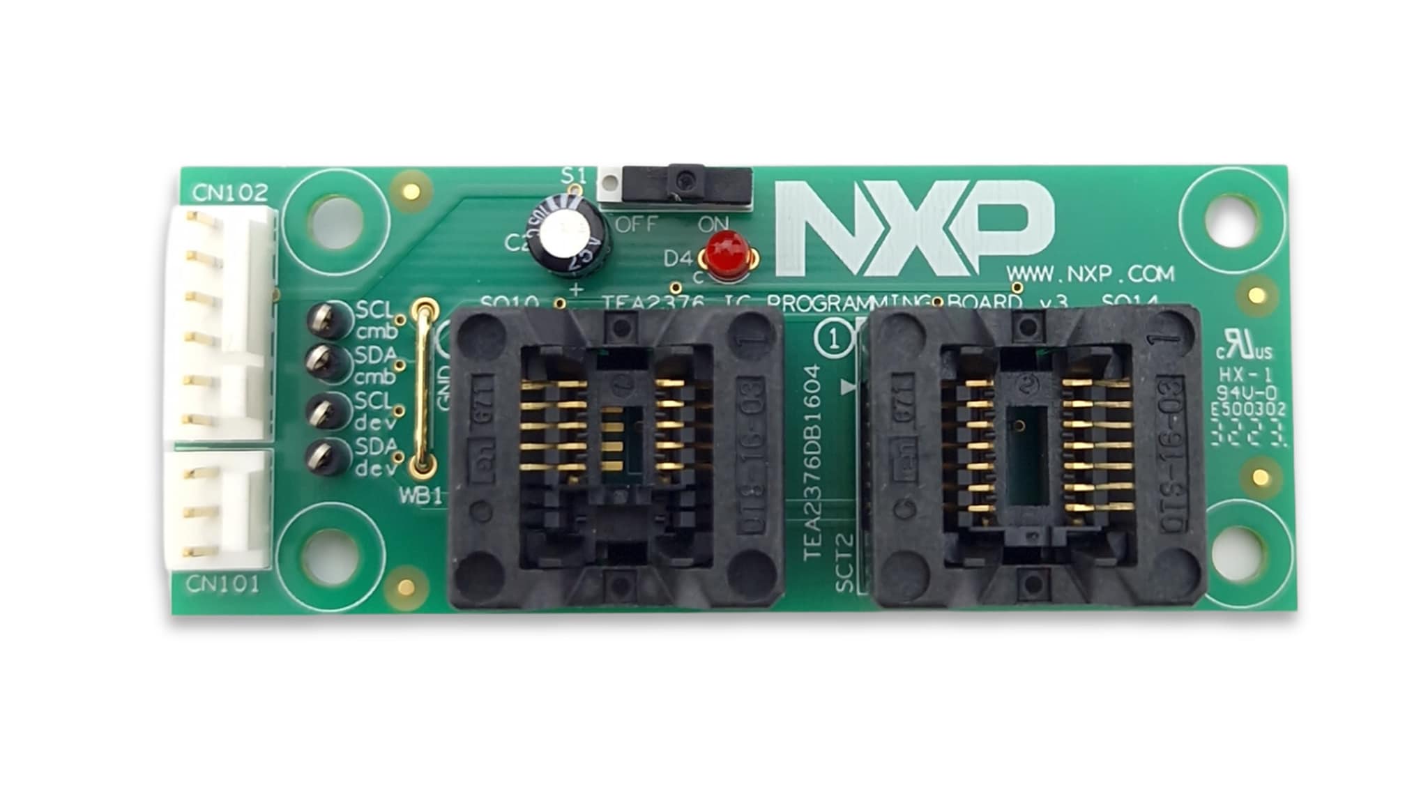
- TEA2376DB1604v3 programming board
- 20 ICs TEA2376DT
1.2 Additional Hardware
In addition to the kit contents, the following hardware is necessary or beneficial when working with this kit.
RDK01DB1563 USB-I²C Programming Interface
2. Get Hardware
2.1 Board Features
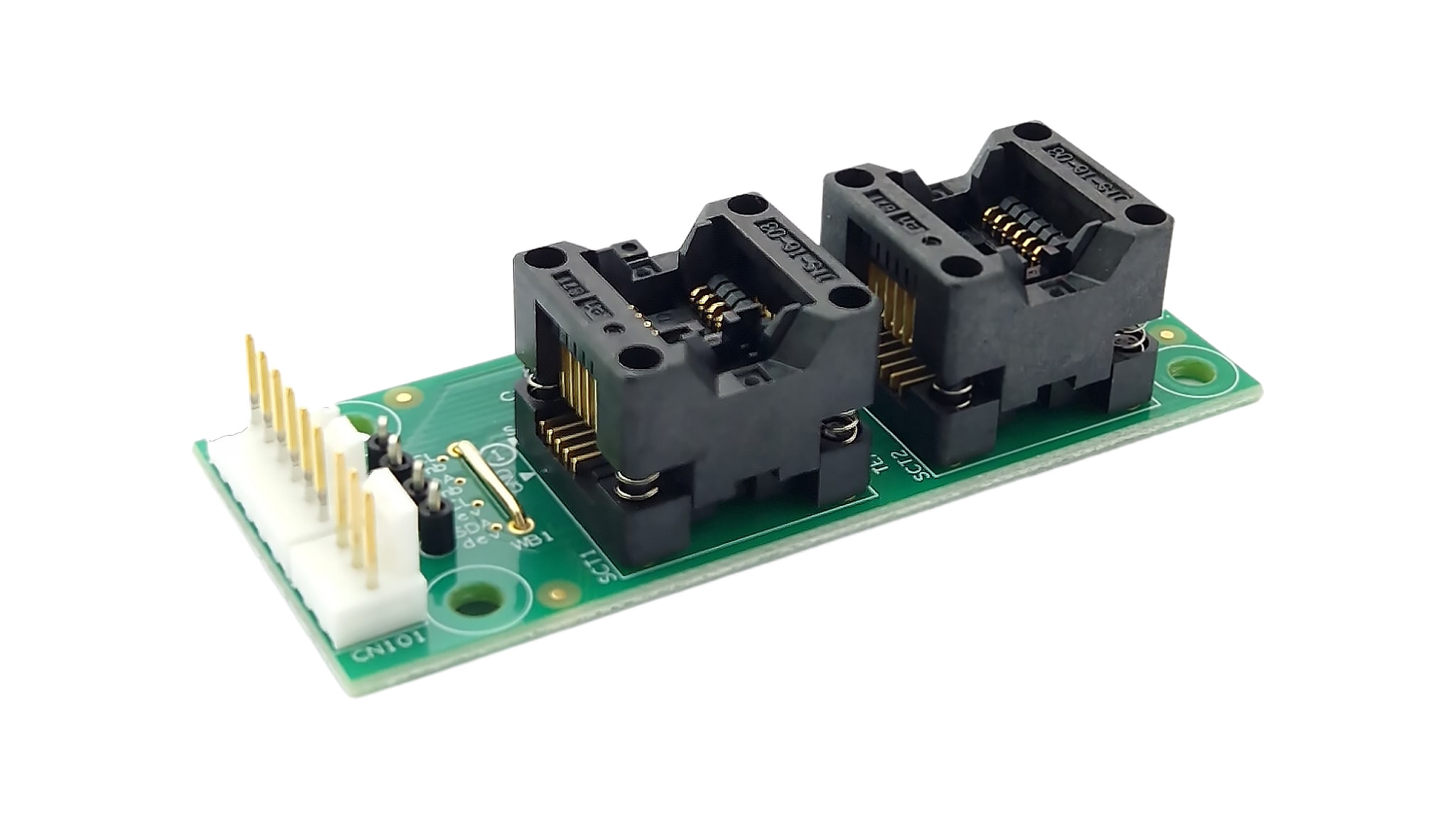
This board can be used for programming small series of TEA2376 samples.
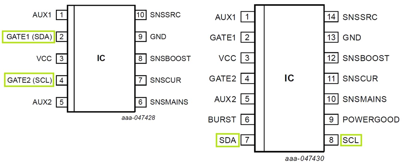
Place an IC in the SO10 or SO14 socket. By connecting both the 3 pin and 6 pin connector to the USB-I²C programming interface, the different IC versions can be programmed after selecting the correct channel with the switch on the USB-I²C interface.
2.2 Board Description
The TEA2376 digital architecture is based on a high-speed configurable hardware state machine ensuring very reliable real-time performance.
Several parameters can easily be configured during evaluation with use of the graphical user interface (GUI) that's part of the TEA2376 Ringo software.
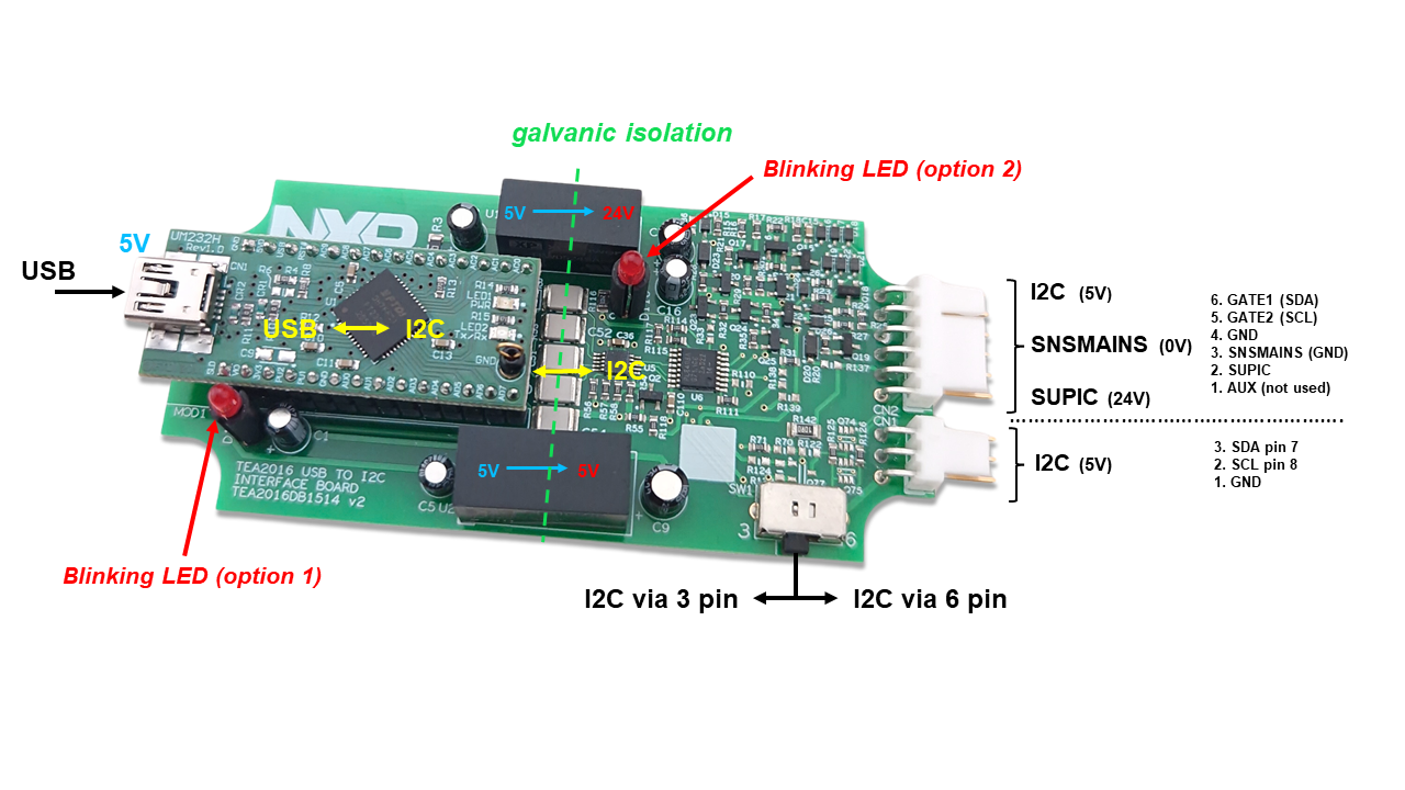
TEA2376 samples can be easily programmed using the TEA2376DB1604v3 board in connection with the RDK01DB1563 USB-I²C demo kit and the TEA2376 Ringo software.
The TEA2376DB1604 board is basically an IC connection board. It connects the I²C signals to the correct pins and supplies the IC VCC by 9 V via series regulator U4.
The SO10 IC socket can be used for the TEA2376AT version and the SO14 IC socket can be used for the TEA2376DT version.
The VCC voltage can be connected or disconnected by switch S1 when exchanging IC samples. A red light from LED D4 indicates that the VCC voltage is applied on the pins. Protection diodes D1 and D2 can help to limit overvoltage on the I²C connection when (dis)connecting the cables, for example.
Test points TP1 - TP4 can be used to measure the I²C communication signals.
3. Configure Hardware
3.1 Configure Hardware
TEA2376 IC samples can be programmed by means of the TEA2376DB1604v3 board + I²C interface (RDK01DB1563). The selector switch on the I²C interface must be set in the right position prior to programming via the GATE pins or the SDA and SCL pins on the TEA2376DT SO14 IC version.
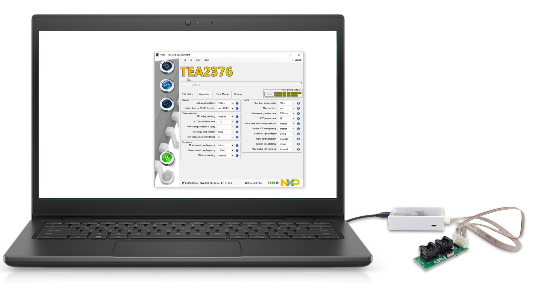
The I²C-USB interface with cables (RDK01DB1563 kit) can be used for several recent NXP power conversion controller ICs that have settings in MTP.
Design Resources
Support
Ringo Software
Q: Ringo.exe does not start.
- A1: The USB-I²C interface driver (FT232) needs to be installed on the computer to enable Ringo software to work
- A2: Make sure you are using a compatible version: 32bit or 64bit
- A3: Ringo is made for Windows operating systems. On other operating systems, you can run it via a windows emulator
Q: Can I work with Ringo without the interface connected?
- A1: Yes, when the USB-I²C interface driver (FT232) is already installed
- A2: To get started, the USB-I²C interface driver (FT232) needs to be installed on the computer to enable Ringo software to work. For this, the interface needs to be connected (one time) to install the driver
Q: When I connect the USB-I²C interface it does not work.
- A1: A driver is needed to make the FT323 module operational. The driver is often automatically installed (plug and play) but sometimes a manual installation is required. Watch the video “installing USB driver manually” on the NXP website. Consult the FTDI website for the latest driver updates
- A2: When you installed the driver and still it does not work: completely (‘delete the driver software for this device’) remove the driver and visit the FTDI chip website for more information on the latest driver version
USB - I²C Interface
Q: There is no communication with the IC.
- A1: Check if the switch on the interface is in the correct position: 3 pin or 6 pin
- A2: Check if the correct cable is connected (or both when using the programming board)
- A3: Check if signal disturbance is blocking communication
Q: I want to make a modification or repair on the board. Is there a circuit diagram?
- A1: The circuit diagram is included in User Manual UM11235. This document is also available in the help tab of the Ringo software
Q: What is the function of the LEDs on the board?
- A1: The Ringo software can use them for indicating that the I²C connection is OK. The indication differs between Ringo versions. In general, slow blinking indicates no communication with the IC. And fast blinking indicates correct communication with the IC
Q: Do I need to buy the RDK01DB1563 kit, or can I also build an interface myself?
- A1: The RDK01DB1563 provides an easy connection with galvanic isolation and can be used for other NXP products as well. The Ringo software working is based on drivers for the UM232H module. It is also possible to use a separate UM232H module from FTDI. And apply it comparably as it is used on the TEA2016DB1514v2 board (circuit diagram included in UM11235)
Programming board
Q: Which cable do I need to connect when I want to work with the programming board?
- A1: connect both 3pin and 6pin cables and select the correct I²C channel for communication
- A2: For a TEA2376AT IC only the 6pin cable connection is required
- A3: For a TEA2376DT IC both 3pin and 6pin cables are required
Q: I want to measure signals or make a modification on the board. Is there a circuit diagram?
- A1: The circuit diagram is included in this document
What is the function of the switch SW1?
- A1: The VCC voltage can be connected or disconnected by switch S1 when exchanging IC samples. A red light from LED D4 indicates that the VCC voltage is applied on the pins
Q: How can I know that the IC is placed correctly in the socket? It fits in two ways
- A1: On the PCB printing there is a mark for pin 1 to make sure that IC is placed correctly