Getting Started with the TJA11xx-EVB Evaluation Board
Contents of this document
-
Out of the Box
-
Get Hardware
-
Install Software
-
Configure Hardware
Sign in to save your progress. Don't have an account? Create one.
Purchase your TJA11xx-EVB
1. Out of the Box
The NXP analog product development boards provide an easy-to-use platform for evaluating NXP products. The boards support a range of analog, mixed-signal and power solutions. They incorporate monolithic integrated circuits and system-in-package devices that use proven high-volume technology. NXP products offer longer battery life, a smaller form factor, reduced component counts, lower cost, and improved performance in powering state-of-the-art systems.
This page will guide you through the process of setting up and using the TJA11xx-EVB board.
1.1 Kit Contents and Packing List
The kit contents include:
- Assembled and tested TJA11xx-EVB evaluation board in an antistatic bag
1.2 Additional Hardware
In addition to the kit contents, the following hardware is needed when working with this board.
- A PHY Sabre expansion board, e.g TJA11xx_STBx
- Cable: USB-A to Micro USB for USB communication with the PHY
1.3 Software
The TJA11XX-EVB Configuration GUI software used to communicate with the board via USB must be downloaded and installed. All listed software is available on the evaluation board's information page at TJA11xx-EVB or from the link provided.
2. Get Hardware
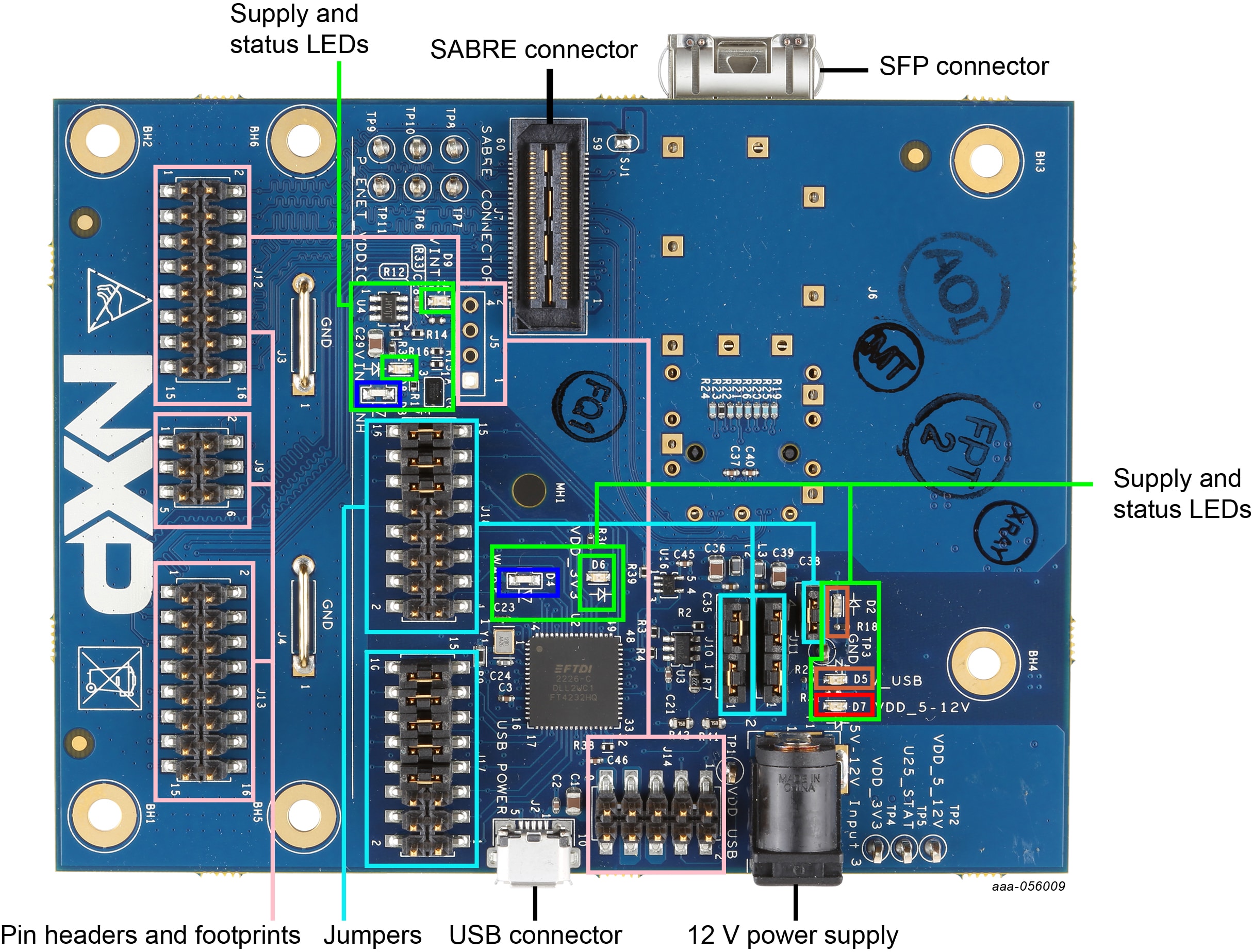
2.1 Board Features
- Evaluation of hardware pinstrapping options on the expansion board
- LEDs to indicate supply status and PHY signals
- Several supply options can be configured - with external supplies, all possible options can be evaluated
- All signals accessible via pinheaders
- CMOS xMII interface accessible via pinheader
- SGMII interface accessible via SFP cage
- JTAG connection accessible
- SMI accessible in several different modes including via USB
Several board-level features were implemented to simplify operation while allowing room for customization:
- The entire board can powered via USB
- SMI access via USB is possible, software support is provided in the form of a GUI-tool and a python API
- SMI+xMII pinheaders are placed in such a way that 2 boards can be connected back-to-back
- All serial interfaces supported by the sabre specification are accessible via USB (SPI, I²C, SMI)
- Unused pins on the USB-to-GPIO IC are brought to pinheaders and can be used for custom functions
- Supplies routed to the sabre daughter expansion can be switched via enable signals
2.2 Board Description
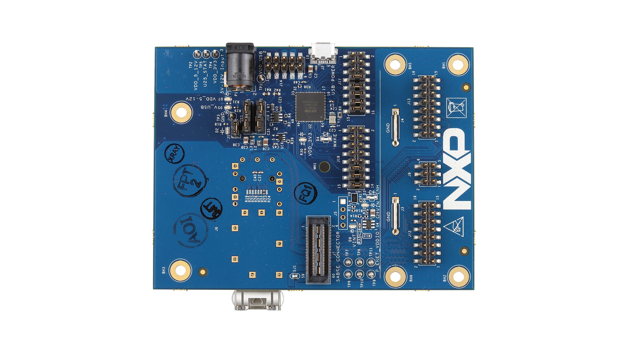
The TJA11xx-EVB evaluation board is designed to be used with PHY expansion boards that support the Sabre connector.
The EVB allows access to all signals on the expansion board that are routed to the Sabre connector and provides power to the expansion board. When combined with the features offered by the Sabre expansion cards, a number of hardware tests can be performed.
3. Install Software
3.1 Install Software
The TJA11xx-EVB Configuration GUI software under secure file, used to communicate with the board via USB must be downloaded and installed from the NXP website.
4. Configure Hardware
4.1 Configure Hardware
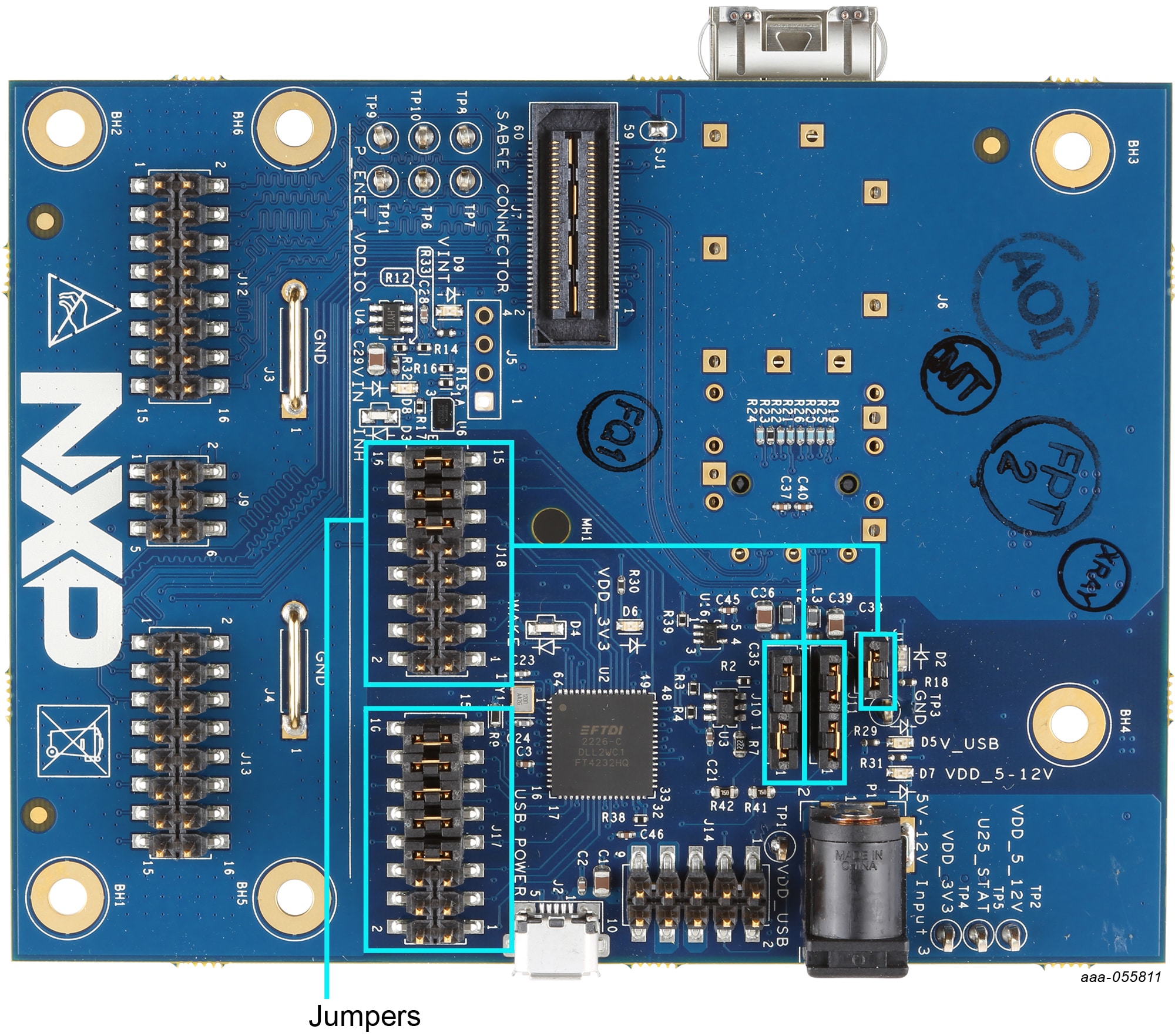
The TJA11xx-EVB board cannot be used standalone. A PHY expansion board with a supported 100/1000 BASE-T1 PHY must be plugged into the EVB before it can be used. The following jumper settings should be checked before plugging in the expansion board and applying power (see Figure 2).
| Function | Setting | Description | |
|---|---|---|---|
| USB system | J1: 1-2 |
Power USB subsystem whenever USB power is available | |
| Supply |
J5: open/unassembled
|
3.3 V and 5-12 V power rails on Sabre connector enabled by default | |
| SMI configuration | J10: 1-2, 3-4
J11: 1-2, 3-4
|
SMI interface connected between USB-IC, Sabre connector and extension header | |
| SPI | J17:7-8, 9-10, 11-12, 13-14, 15-16 |
SPI interface from USB-IC connected to Sabre connector | |
| I²C | J18: 9-10, 11-12, 13-14, 15-16 |
I²C interface from USB-IC connected to Sabre connector | |
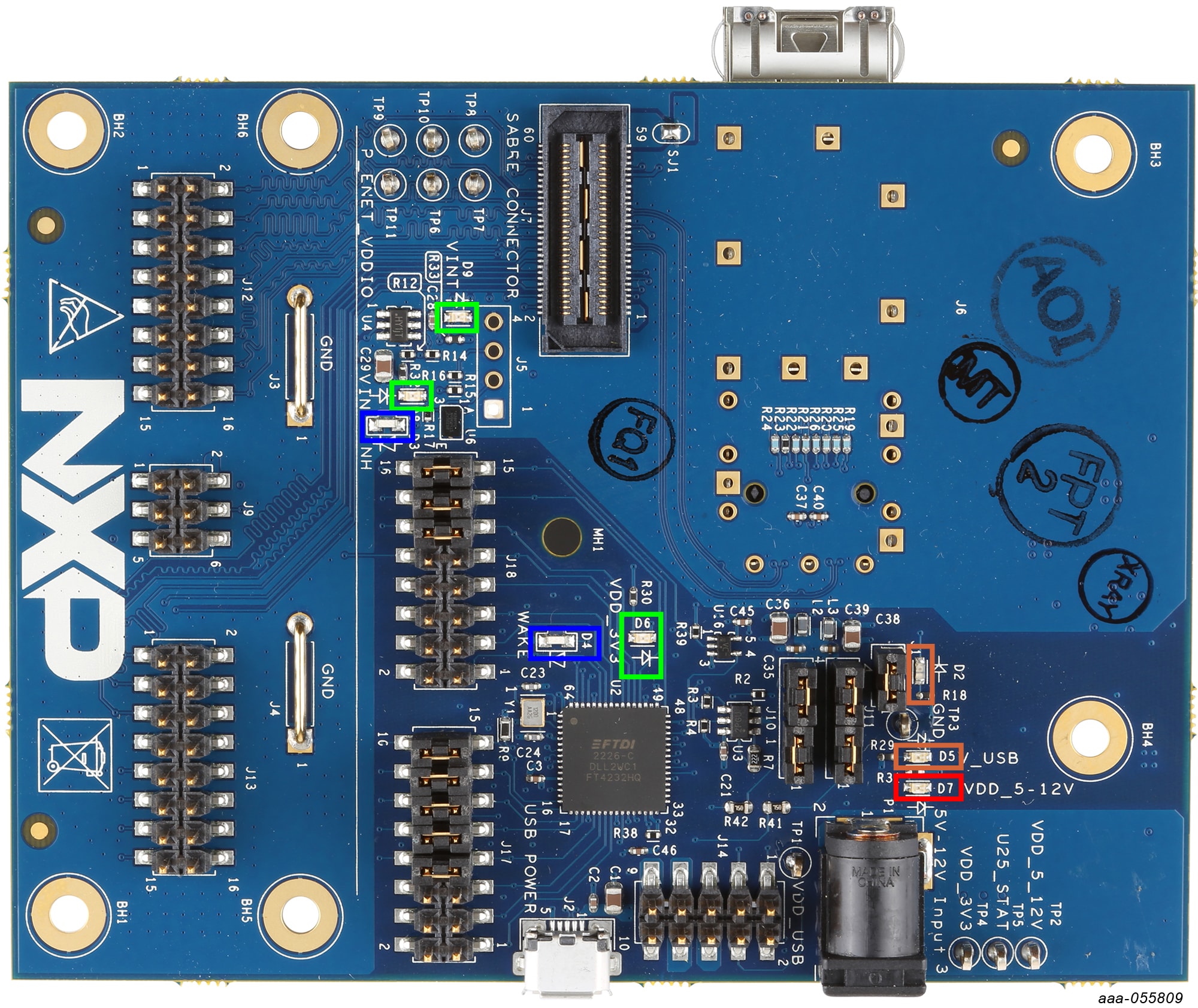
After plugging the Sabre expansion board onto the EVB and powering it up by connecting it via USB to a computer, check the following LEDs (see Figure 3):
- Orange:
D5- supply from USB connector - Green:
D8- supply available after input selector and USB switch - Green:
D6- 3.3 V power available - Green:
D9- 5-12 V power available
Once the hardware has started up successfully, the GUI-Tool can be loaded and used to access the PHY.
Design Resources
Board Information
Available to selected customers only (non disclosure agreement (NDA) required). Contact your local NXP sales representative for more information.
Additional References
In addition to our Automotive Ethernet PHY Transceivers product pages containing details of our PHY devices, you may also want to visit: