NFC Eval Board Setup Guides
Contents of this document
-
Out of the Box
-
Get to Know the Hardware
-
Install Software
-
Configure Hardware
Sign in to save your progress. Don't have an account? Create one.
Purchase your P3T1035xUK Arduino® Shield Evaluation Board
1. Out of the Box
The NXP analog product development boards provide an easy-to-use platform for evaluating NXP products. The boards support a range of analog, mixed-signal and power solutions. They incorporate monolithic integrated circuits and system-in-package devices that use proven high-volume technology. NXP products offer longer battery life, a smaller form factor, reduced component counts, lower cost, and improved performance in powering state-of-the-art systems.
This page will guide you through the process of setting up and using the P3T1035XUK-ARD board.
1.1 Kit Contents and Packing List
The P3T1035XUK-ARD kit contents include:
- Assembled and tested evaluation board in an antistatic bag
1.2 Assumptions
Familiarity with the SPI-bus is helpful but not required.
1.3 Static Handling Requirements
This device is sensitive to ElectroStatic Discharge (ESD). Therefore care should be taken during transport and handling. You must use a ground strap or touch the PC case or other grounded source before unpacking or handling the hardware.
1.4 Minimum System Requirements
- PC Pentium processor (or equivalent)
- One USB port (either 3.0 or 2.0 or 1.1 compatible)
- Windows 7, 8, or 10
- OM13089 MCU board (from www.nxp.com)
1.5 Power Requirements
The MIMXRT685-EVK MCU board obtains power from the PC USB port. Two USB parts can be connected to the MIMXRT685-EVK MCU board simultaneously. Use an external power supply option if exceeding the USB port current capabilities.
2. Get to Know the Hardware
2.1 Board Features
- A complete evaluation platform for the P3T1035XUK I³C, I²C-bus, 0.5 °C accuracy, digital temperature sensor
- Easy to use GUI based software demonstrates the capabilities of the P3T1035XUK
- On-board temperature sensor for system thermal management experiments
- Convenient test points for easy scope measurements and signal access
- USB interface to the host PC
- Power supply from USB port (x2) or external power supply can be used to power P3T1035XUK-ARD evaluation board
2.2 Board Description
The P3T1035XUK-ARD evaluation board features an I³C, I²C-bus, 0.5 °C accuracy, digital temperature sensor. A graphical interface allows the user to easily explore the different functions of the driver. The board can be connected in parallel with other I²C-bus demo boards to create an evaluation system
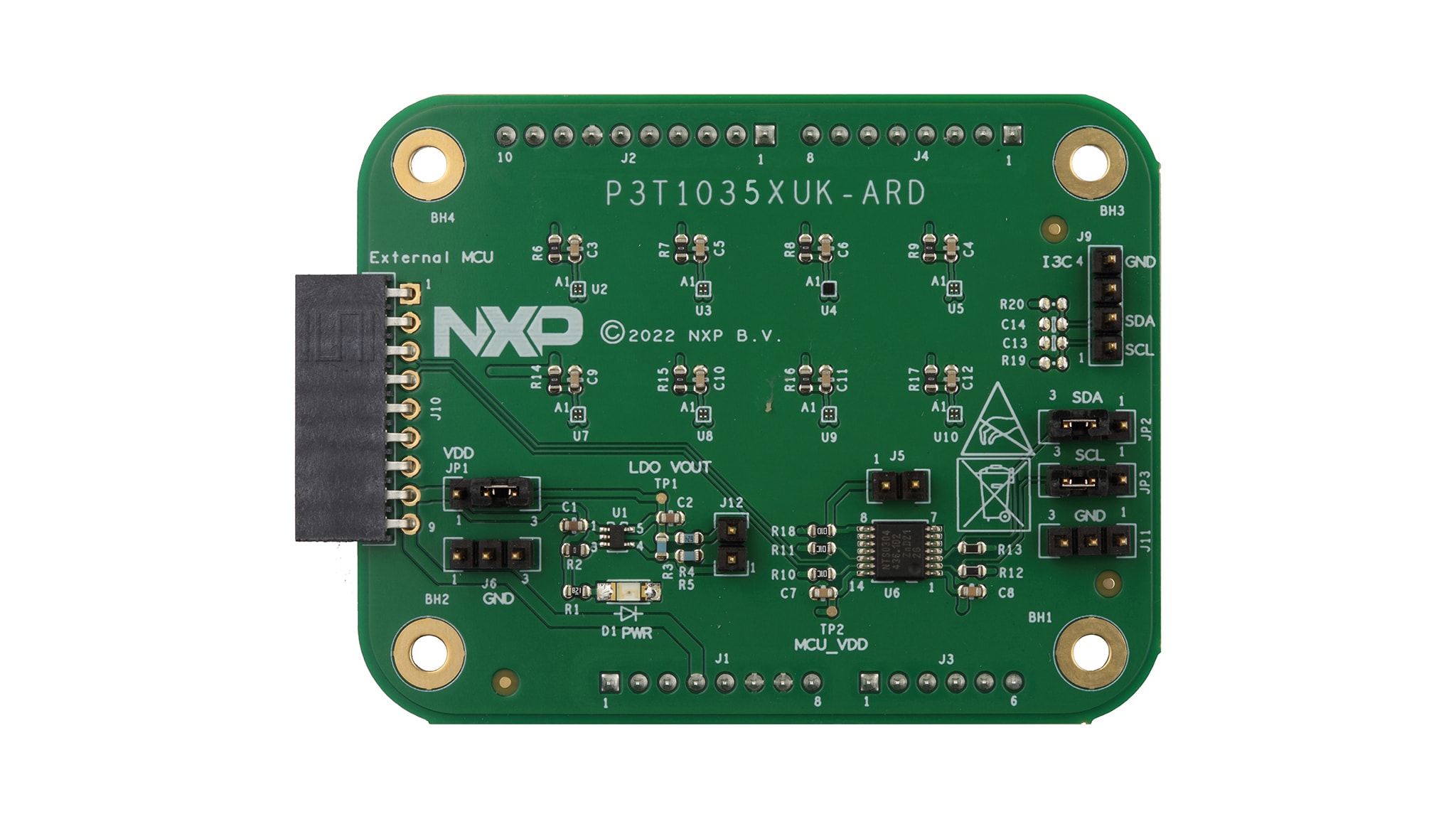
2.3 Board Components
| Device | Description | Location |
|---|---|---|
| P3T1035XUK | I³C, I²C-bus, 0.5 °C accuracy, digital temperature sensor | U2 |
| TPS71701DCKT | Adjustable output voltage LDO | U1 |
| NTS0304EPWJ | 4-bit dual supply translating transceiver | U6 |
| Green LED | Power supply on LED | D1 |
3. Install Software
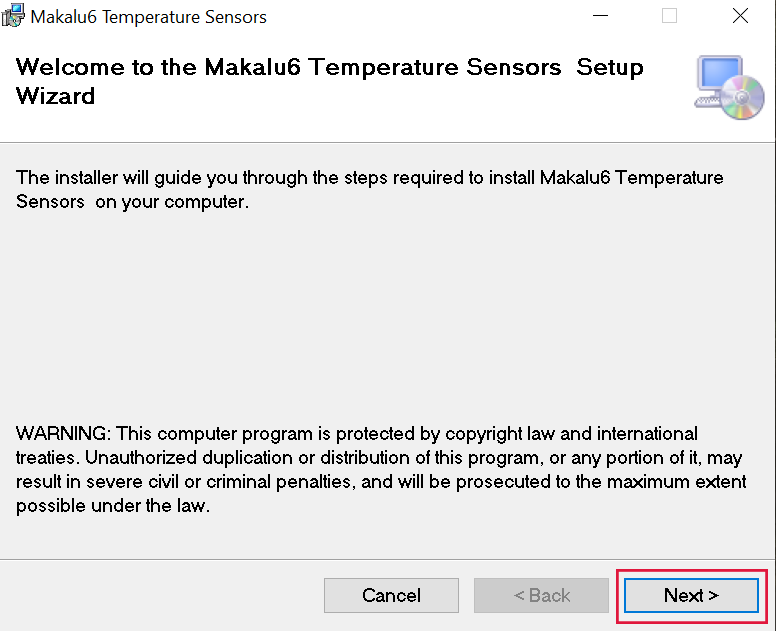
3.1 Install P3T1035XUK-ARD Demo GUI
- Double click on “setup.exe” to install P3T1035XUK-ARD demo GUI
-
Click “Next” button three times to complete installation
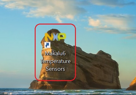
3.2 Run Makalu6 Temperature Sensors GUI on Windows 7,8,10 PC
-
Double click on “Makalu6 Temperature Sensors” icon to start GUI.
-
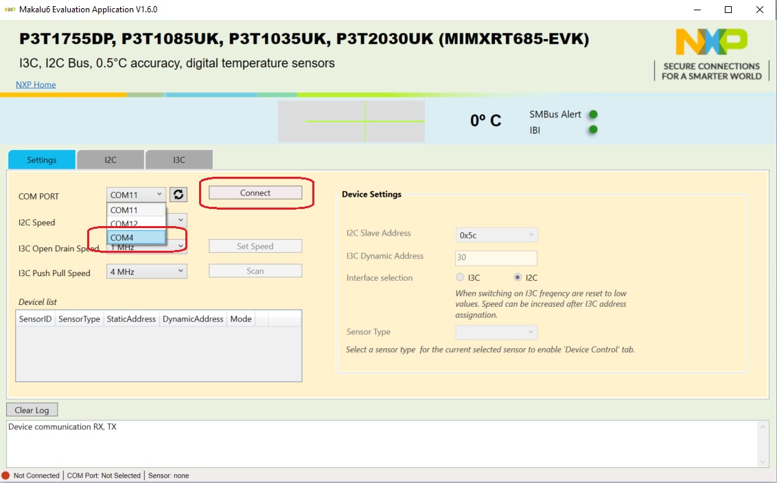
Select proper COM port (last COM port normally) and click “Connect” button to connect MIMXRT685-EVK board.
-
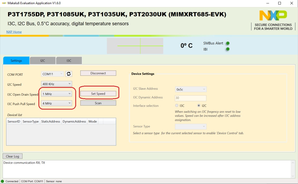
Use Setting tab to select I²C and I³C-bus speed, and click on the “Set Speed” button.
-
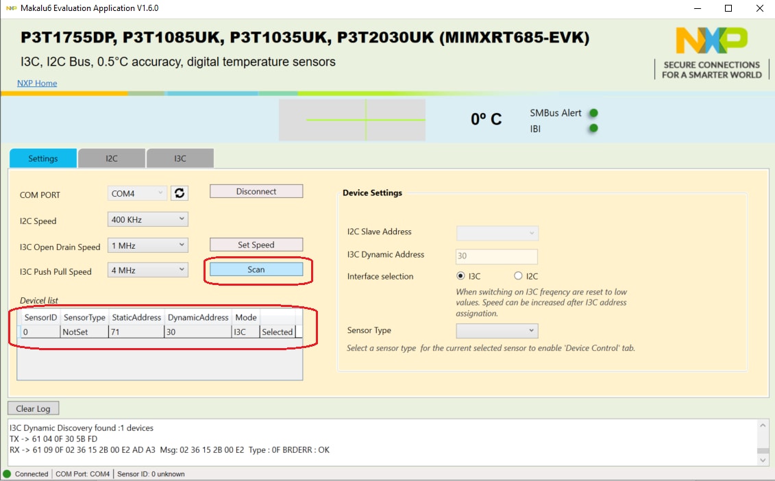
Click on “Scan” button to discover any NXP temperature sensor target address on the evaluation board.
-
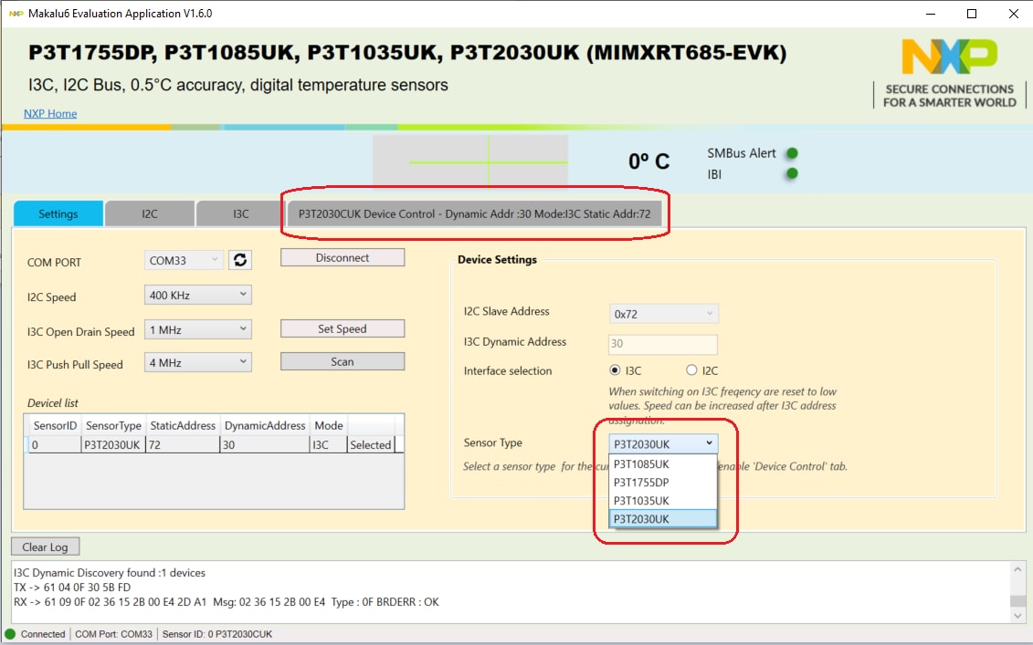
Use Sensor Type to select which temperature sensor to be tested on the evaluation board.
-
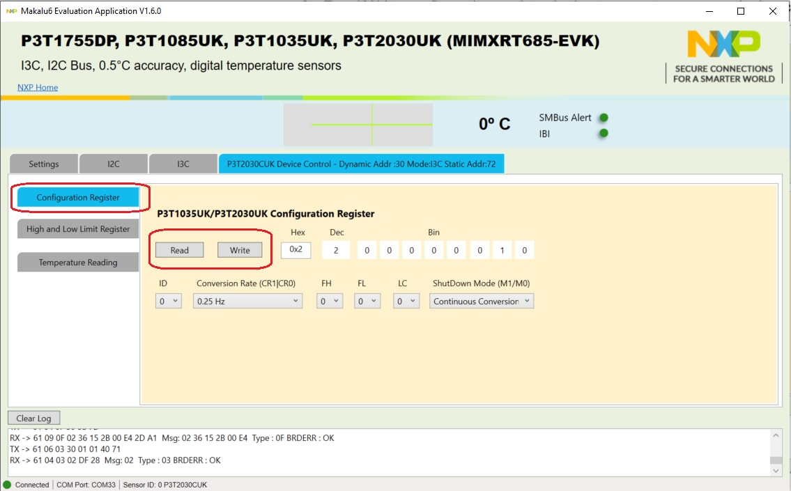
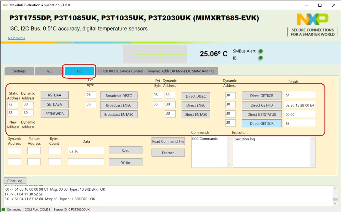
Read/Write configuration register in the temperature sensor device control tab.
-
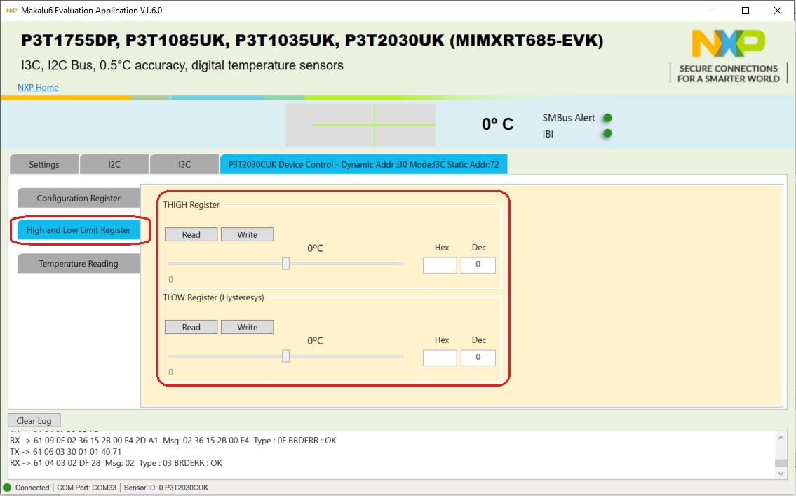
Read/Set THIGH (high limit) and TLOW (low limit) registers in the temperature sensor device control tab.
-
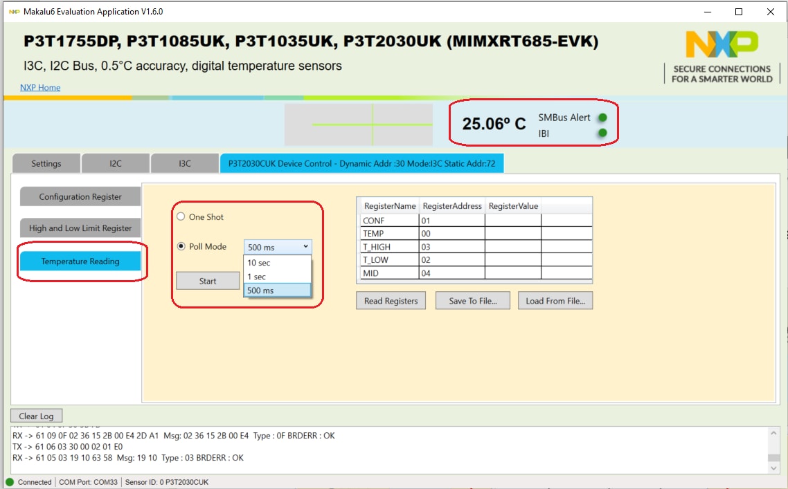
Perform one-shot or polling temperature read in the temperature sensor device control tab.
-
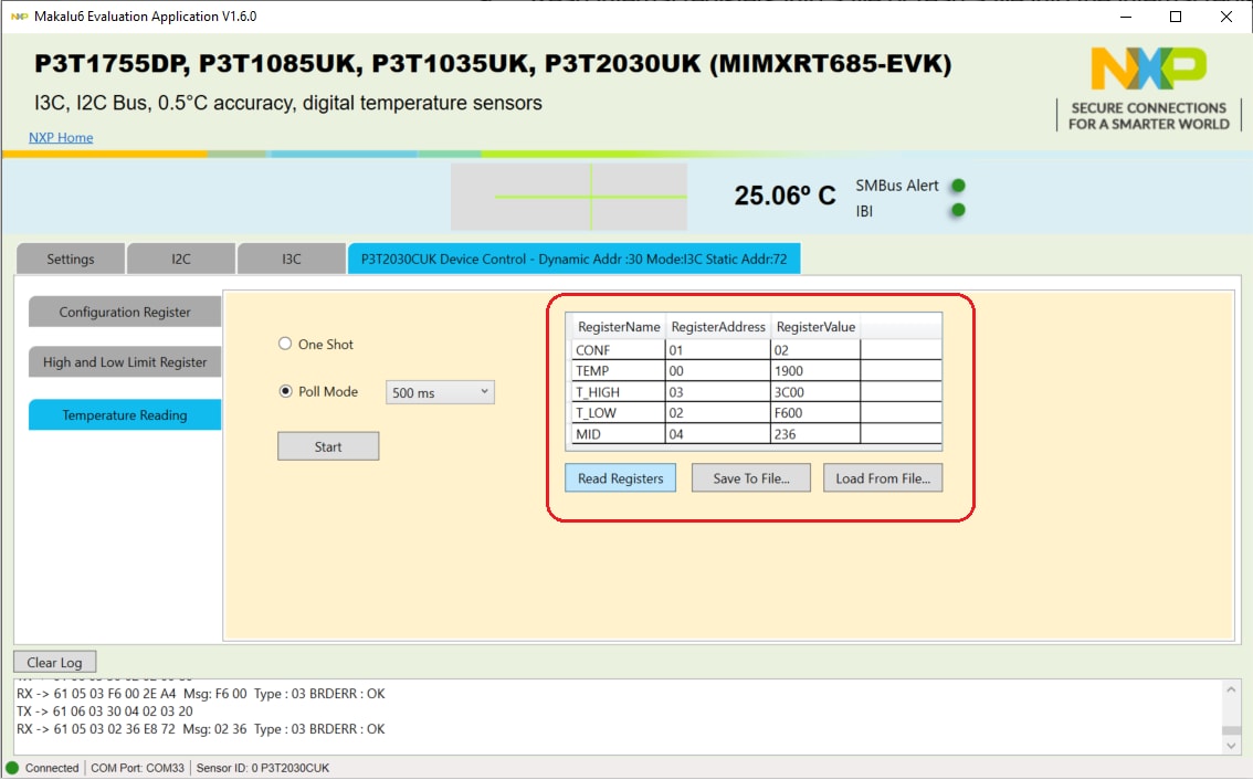
Read internal registers into a file or read a file into the internal registers in the in the temperature sensor device control tab.
-
Perform I³C general tests in the I³C tab.
-
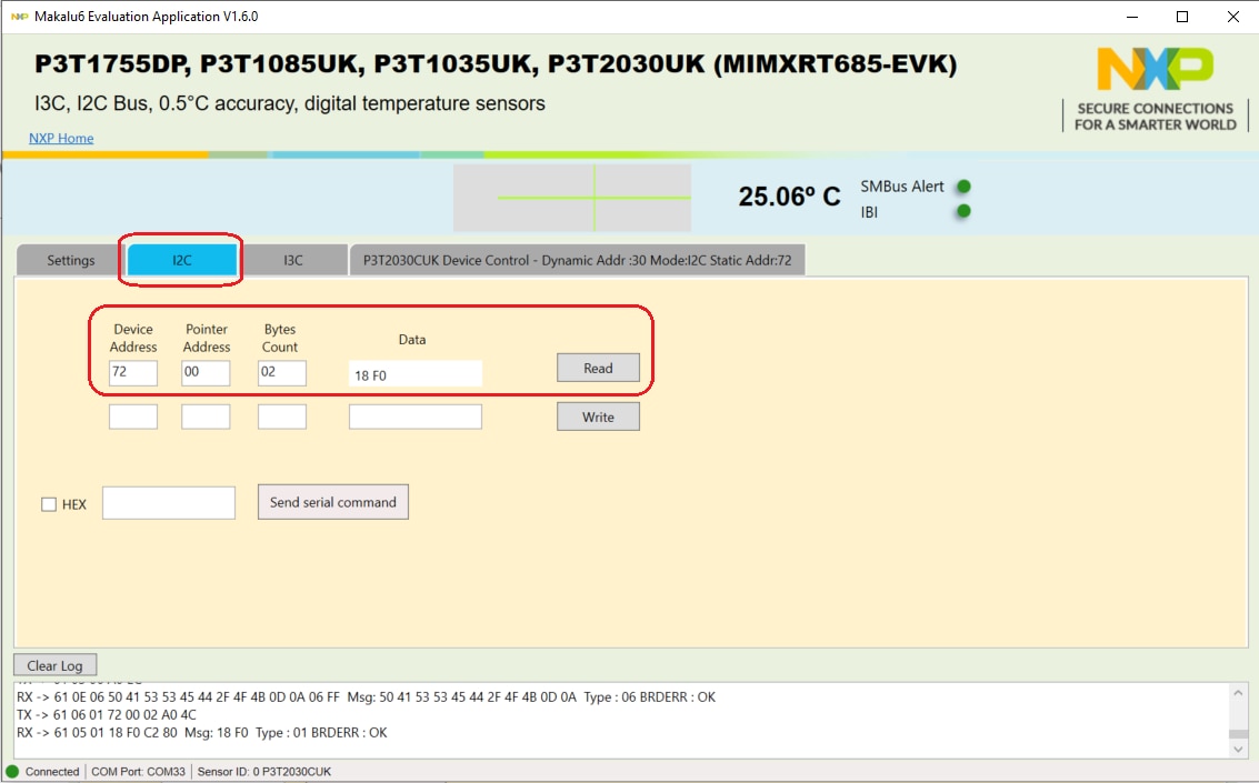
Perform I²C general tests in the I²C tab.
4. Configure Hardware
4.1 Configure the Hardware
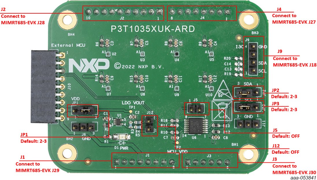
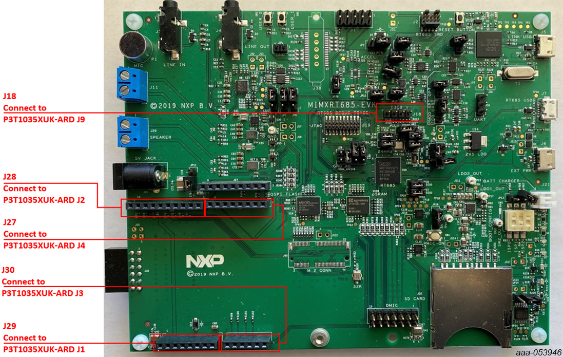
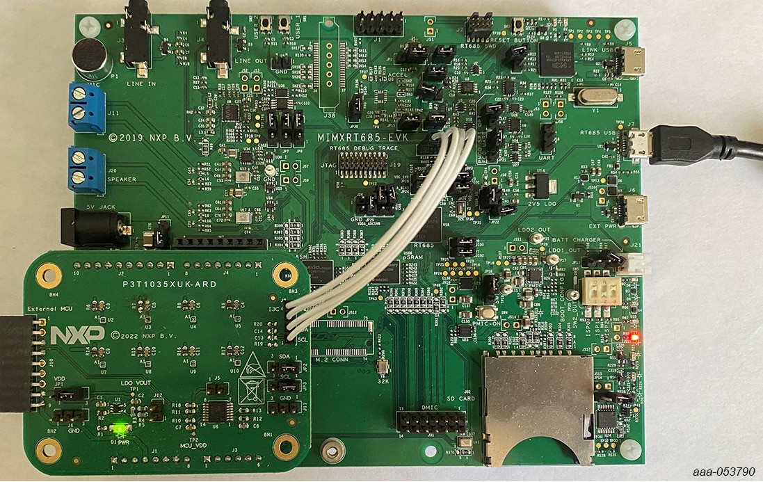
P3T1035XUK-ARD EV board and MIMXRT685-EVK MCU board connection
P3T1035XUK-ARD evaluation board is connected to the MIMXRT685-EVK MCU board using four connectors (J1/J2/J3/J4 on P3T1035XUK-ARD board and J27/J28/J29/J30 on MIMXRT685-EVK board) for I²C-bus and power supply, and one connector (J9 on P3T1035XUK-ARD board and J18 on MIMXRT685-EVK board) for I³C-bus.
The MIMXRT685-EVK MCU board communicates with P3T1035XUK demo GUI through PC USB port and uses I²C or I³C-bus to communicate to P3T1035XUK.
Design Resources
Board Information
Additional References
In addition to our P3T1035xUK, I³C, I²C-Bus, ±0.5 °C Accuracy, Digital Temperature Sensor page, you may also want to visit: