Application Note (2)
Quick Reference Guide (1)
-
USB-PD/QC4.0 Development Kit A[USB-PD-QC-DEVKIT]
User Guide (1)
-
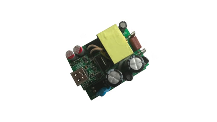
TEA1993DB1357 synchronous rectifier controller demo board[UM10963]Getting Started