S32K144 Motor Control Kit Guides
Contents of this document
-
Out of the Box
-
Get Software
-
Plug It In
-
Build
Sign in to save your progress. Don't have an account? Create one.
Purchase your S32K144 BLDC/PMSM Development Kit
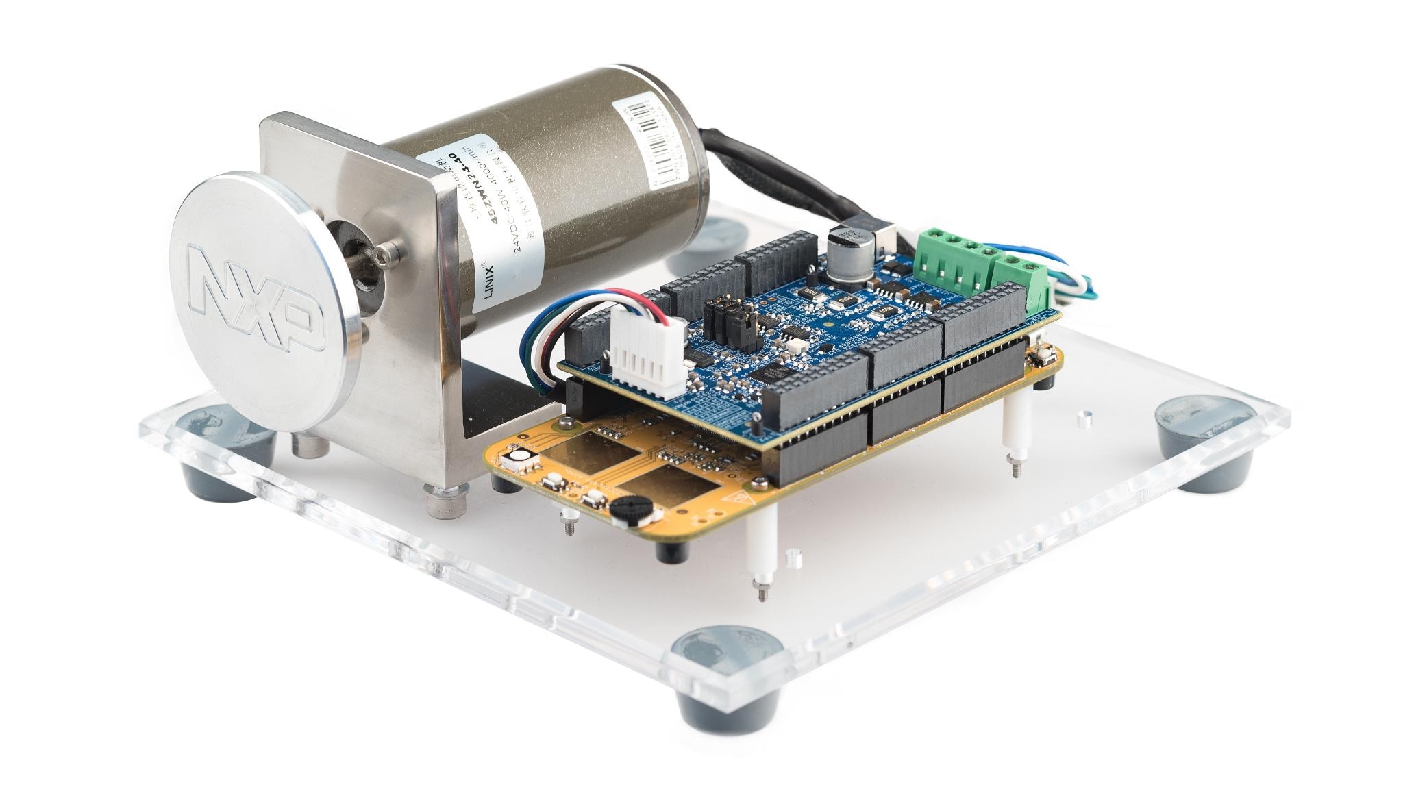
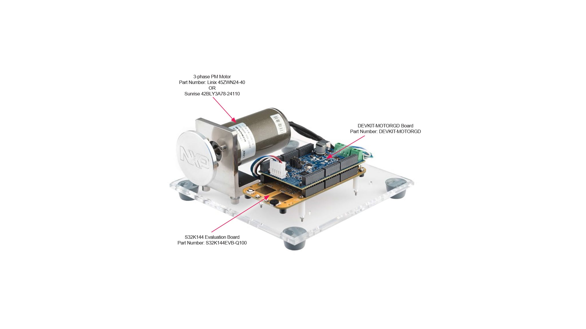
1. Out of the Box
1.1 Get to Know the Development Kit
You can watch the video or follow the below step-by-step guide to set up your MCSPTE1AK144:
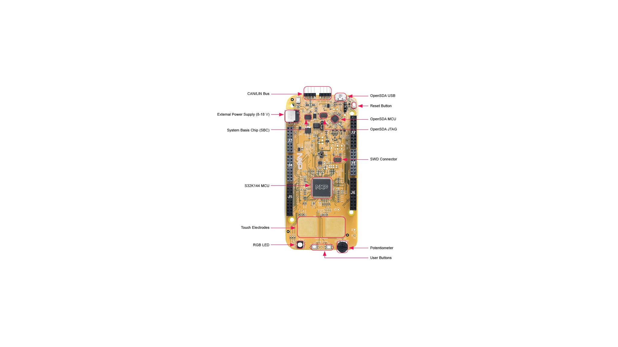
1.2 Get to Know the Evaluation Board
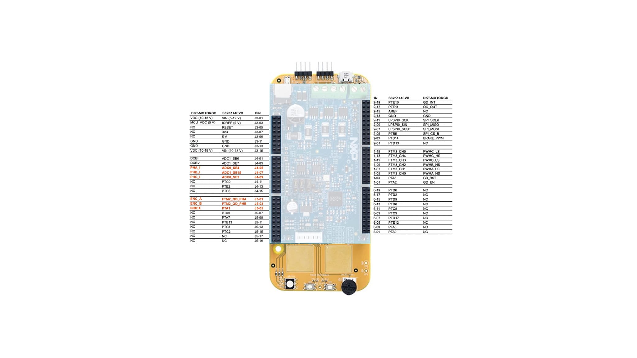
1.4 Understanding the Header/Pinout for the PMSM Motor Control
S32K144EVB controls the DEVKIT-MOTORGD through the inner pins of the I/O headers.
Inner pins of the I/O headers are Arduino® compatible. Pins in red are configurable.
This is the pin configuration for the PMSM motor control:
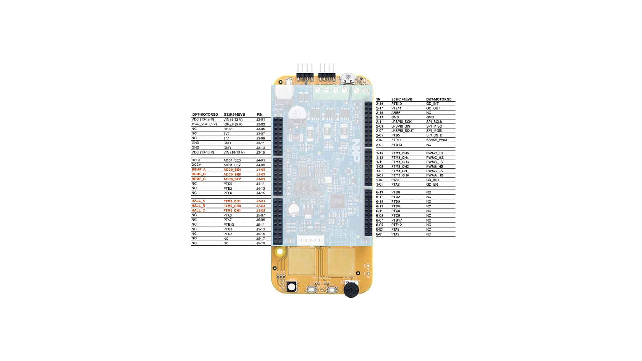
1.5 Understanding the Header/Pinout for the BLDC Motor Control
S32K144EVB controls the DEVKIT-MOTORGD through the inner pins of the I/O headers.
Inner pins of the I/O headers are Arduino compatible. Pins in red are configurable.
This is the pin configuration for the BLDC motor control:
2. Get Software
2.1 Download the Development Kit - Application Software
The software package includes projects for most typical hardware configurations.
Download MCSPTE1AK144 Development Kit Application Software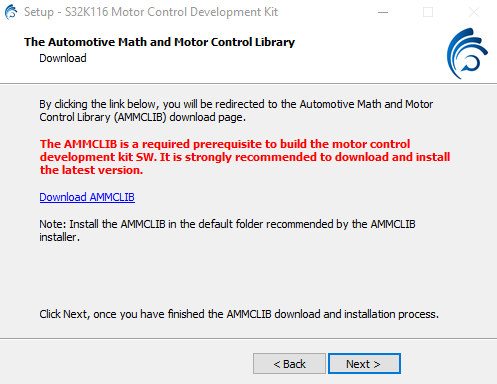
2.2 Get the Integrated Development Environment (IDE)
MCSPTE1AK144 performs better when using S32 Design Studio IDE for Arm®
Download S32 DESIGN STUDIO IDE2.3 Get the Run-Time Debugging Tool
MCSPTE1AK144 evaluation board performs better when using the FreeMASTER tool for run-time debugging.
Download FreeMASTER tool3. Plug It In
3.1 Set Up Jumpers in S32K144EVB Evaluation Board
| Jumper | Setting | Option | Description |
|---|---|---|---|
J104 |
1-2 | Reset Signal | Reset signal to OpenSDA, use to enter into Open SDA bootloader mode |
| 2-3 | Reset signal direct to the MCU, use to reset S32K144 (default) | ||
J107 |
1-2 | Board Powering | S32K144 powered by 12 V power source (default) |
| 2-3 | S32K144 powered by USB micro connector | ||
J109/J108 |
Open | CAN | CAN termination resistor is disconnected |
| Short | CAN terminator resistor is connected (default) |
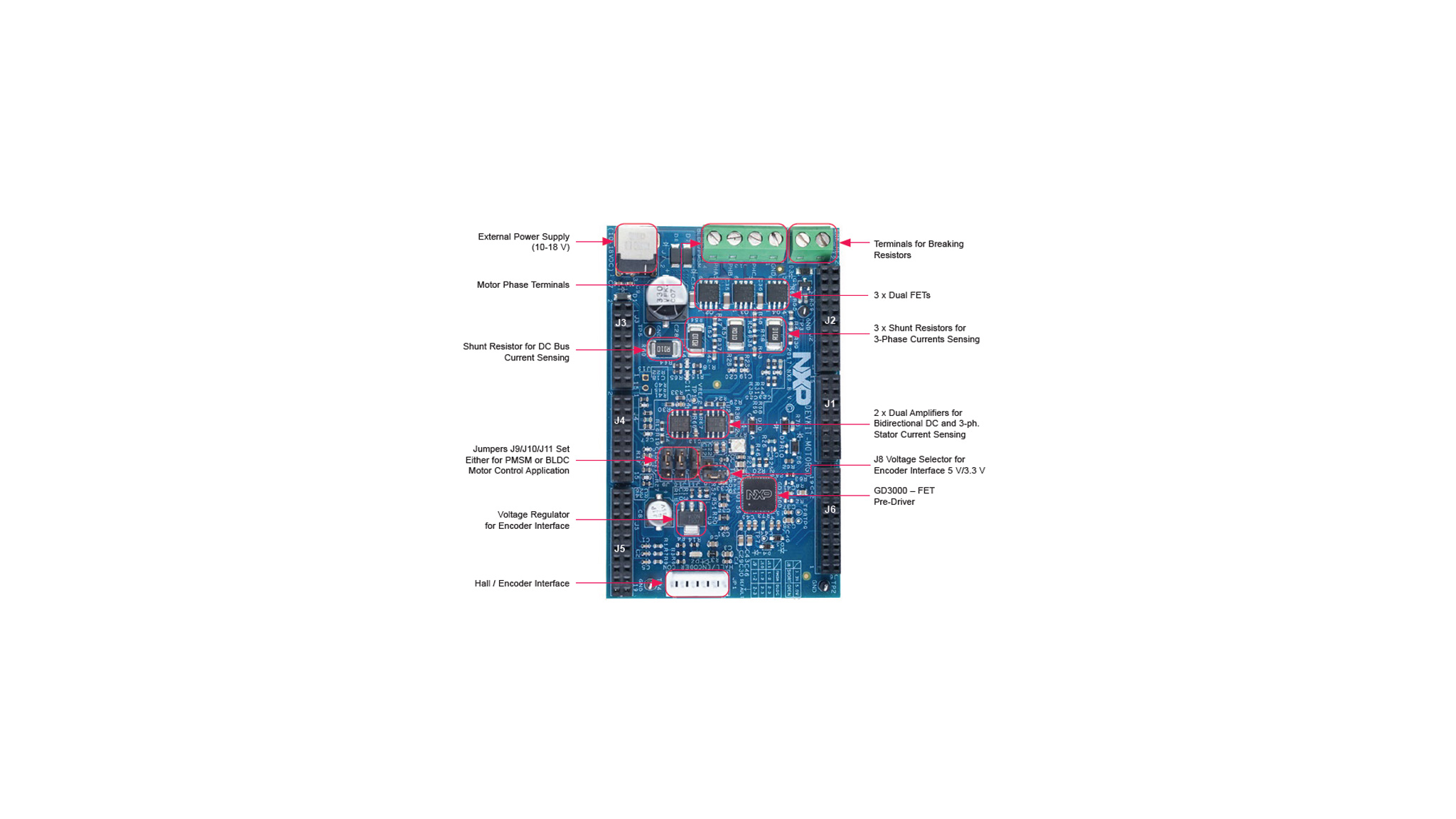
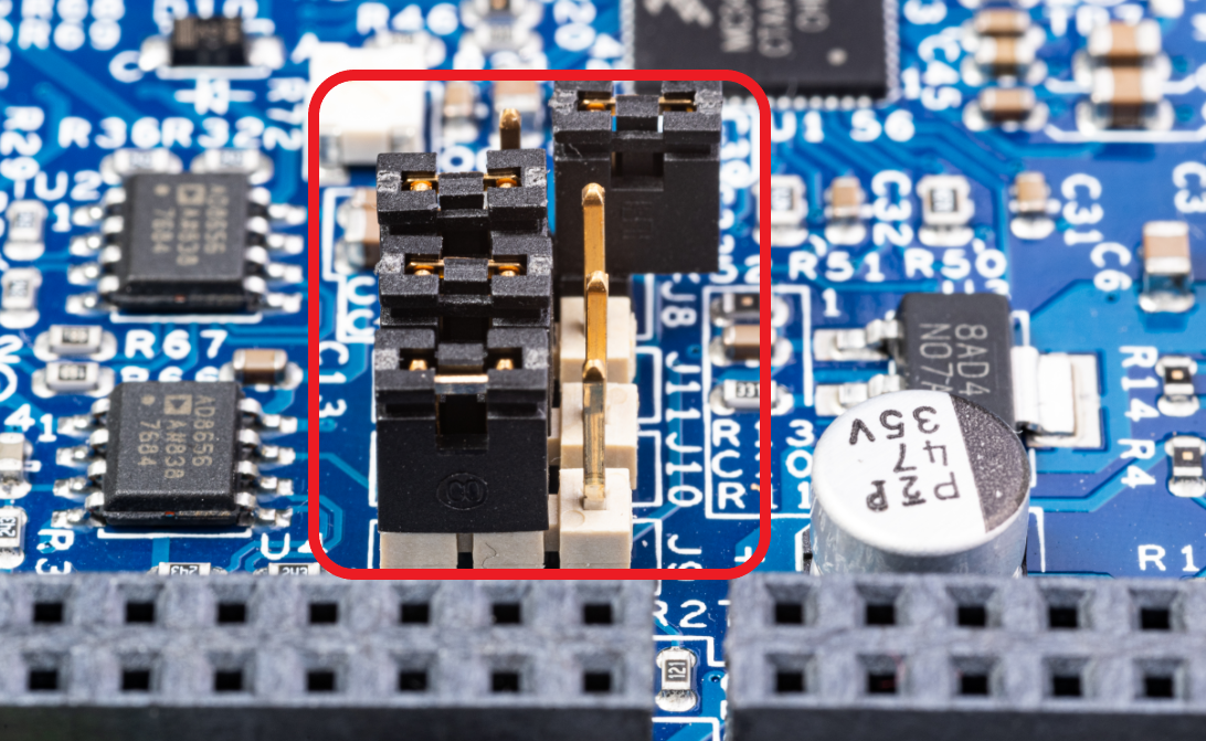
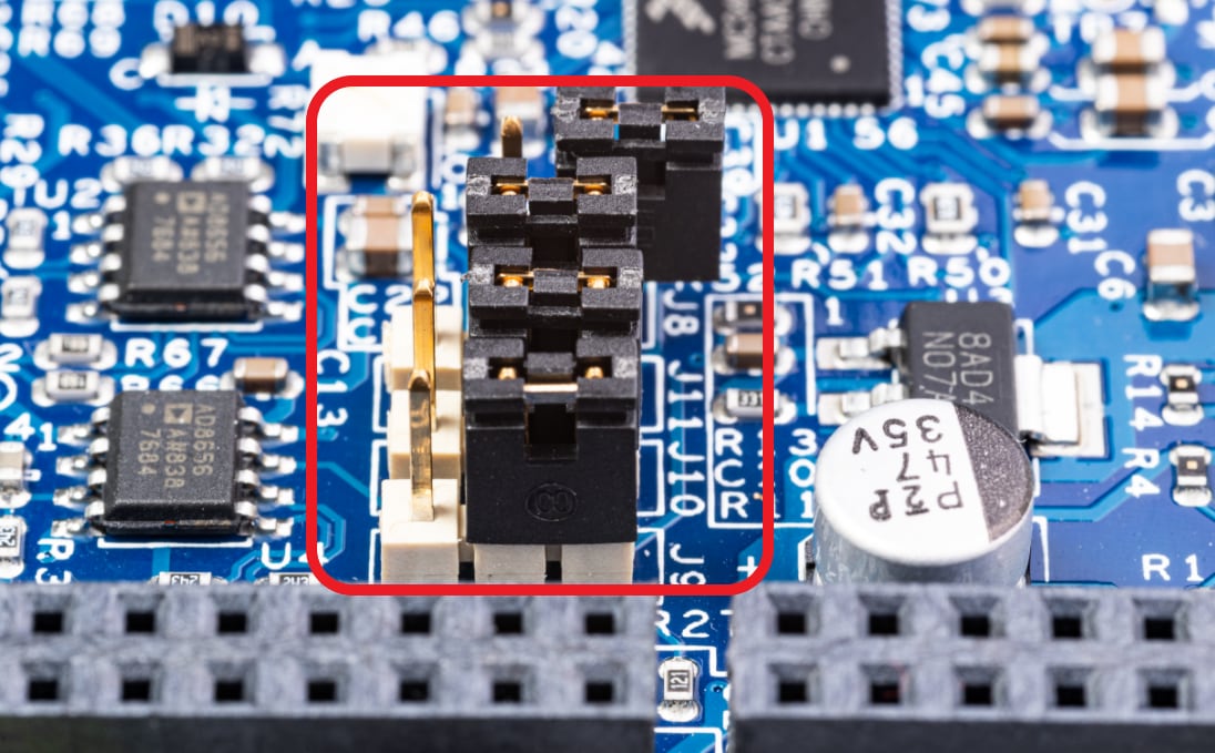
3.2 Set Up Jumpers in the DEVKIT-MOTORGD Evaluation Board
| Jumper | Setting | Option | Description |
|---|---|---|---|
J8 |
Short | HALL/Encoder interface | Voltage level for HALL/Encoder interface is 3.3 V |
| Open | Voltage level for HALL/Encoder interface is 5.0 V (default) | ||
J9/J10/J11 |
1-2 | Motor Type | Bidirectional 3-phase current sensing for PMSM FOC (sinusoidal) motor control |
| 2-3 | 3-phase back-EMF voltage sensing for BLDC six-step (trapezoidal) sensorless motor control |
3.3 Configure S32K144EVB and DEVKIT-MOTORGD Boards
1. Ensure default S32K144EVB and DEVKIT-MOTORGD jumper options.
2. Ensure jumper
J107 in S32K144EVB and
DEVKIT-MOTORGD is in position 1-2 for powering board from 12 V power supply.
3. Place DEVKIT-MOTORGD jumpers
J9,
J10,
J11 to position 1-2 for PMSM
application or 2-3 for BLDC application, The jumper
J8 stays open for 5 V HALL
sensors.
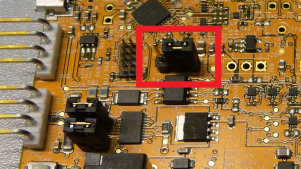
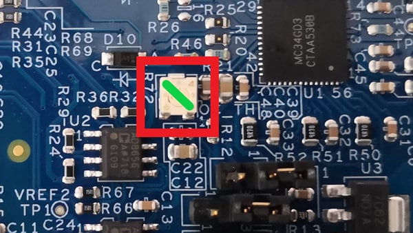
4. Make sure the potentiometer for overcurrent comparator is set in position (slightly to the left from the middle) for approximately 8 – 10 A.
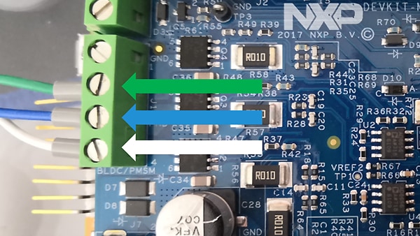
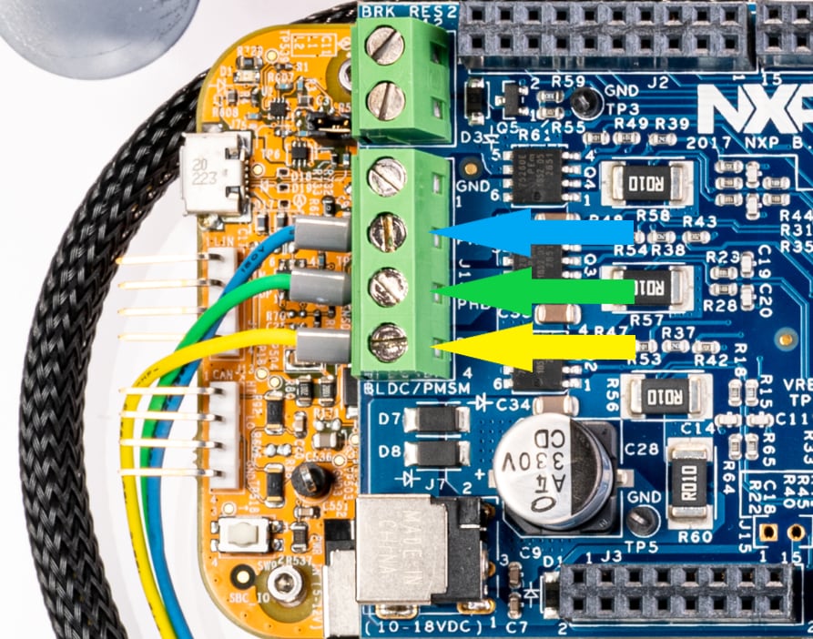
3.4 Plug In the Motor
Ensure that the motor phase wires are in the following order, from phase A to phase C:
| Phase/Motor | Linix | Sunrise |
|---|---|---|
| A | White | Yellow |
| B | Blue | Green |
| C | Green | Blue |
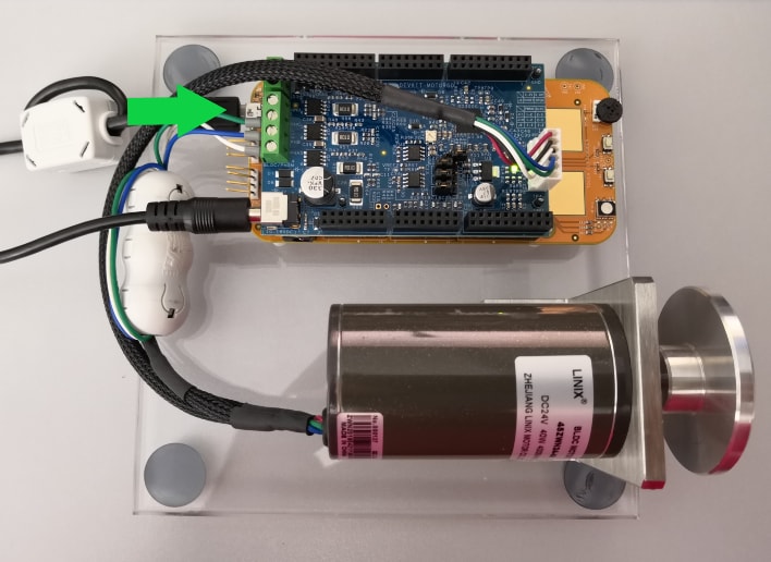
3.5 Plug in the Power Supply
Connect the 12 V power supply for the S32K144EVB and DEVKIT-MOTORGD boards, together with the 3-phase PM Motor. S32K144EVB is configured for powering from DEVKIT-MOTORGD board. Keep the DC supply voltage within the range of 8 to 18 V.
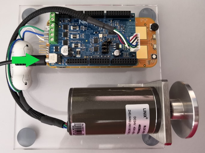
3.6 Connect the USB Cable
Connect S32K144EVB to the PC using the USB cable.
4. Build
4.1 Select Application and MCU Programing
Let's take it for a test drive.
Select the appropriate PMSM or BLDC motor control application from the
installed directory NXP\MCSPTE1AK144\sw.
Reprogram the MCU using S32 Design Studio:
To import the installed application software project in the S32 Design Studio
IDE for Arm®:
- Launch S32DS for Arm
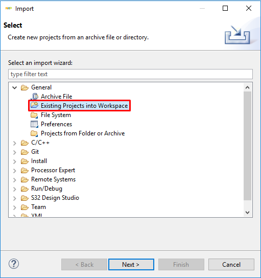
- Go to File → Import, then select General → Existing Projects into Workspace
-
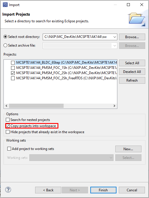
Navigate to the installed application directory:
NXP\MC_DevKits\MCSPTE1AK144\swand choose appropriate project and click O. Then, click Finish -
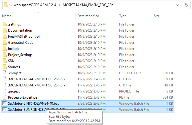
Use File Explorer to run one of the batch files in your project for loading
appropriate files with motor parameters. Do not run batch files from S32DS.
The default motor parameters are for Sunrise motor type
Optional: These steps should not be necessary since they are automatically executed in the next step.
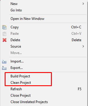
- Right click on the imported project and select Clean
- Right click on the imported project and select Build
4.2 Debug and Load
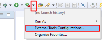
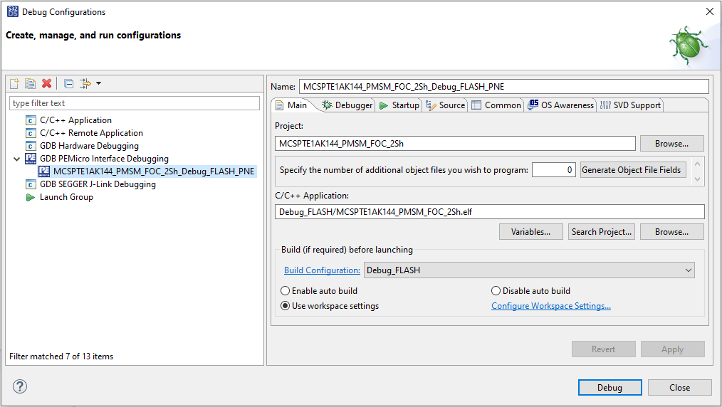
In the S32 Design Studio menu click Run → Debug Configuration and select the predefined debug configuration and click on Debug to start loading built code into MCU.
4.3 Let Code Run
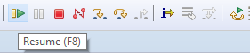
To let the code run, click Resume (or press F8), and use Disconnect to avoid interference between the S32DS IDE debugger and the FreeMASTER tool.

4.4 Set Up the Debugging Tool
- Launch the FreeMASTER application
-
To open the
*.pmpFreeMASTER project<selected project>\FreeMASTER_control, click File → Open Project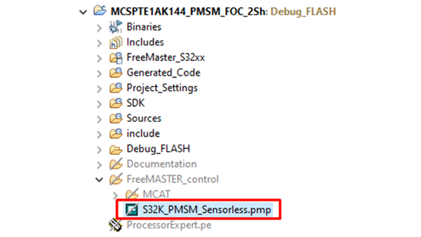
- To enable communication, in the FreeMASTER tool bar, click Go (or press CNTRL+G).
Successful communication displays in the status bar at the bottom as:
RS232 UART Communication;COMn;speed = 115200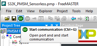
Projects and Tutorials
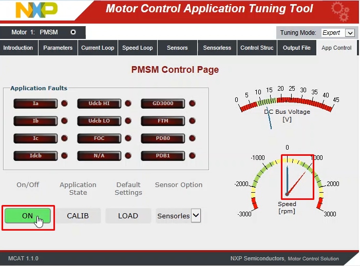
Application Control
1. To display the application control page, click the App Control tab on the Motor Control Application Tuning Tool menu
2. Configure the motor rpms and turn on the motor drive
When the power supply is connected to the DEVKIT-MOTOGD board, the application is in a READY states - steady green LED on S32K144EVB board. RGB LED also indicates:
- READY, INIT states lighting green LED
- CALIB, ALIGN states - flashing green LED
- RUN state - flashing blue LED
- FAULT state - flashing red LED
Check pending faults
In case of pending faults, click the Clear FAULT on the FreeMASTER MCAT
control page, or alternatively press and simultaneously hold
SW2 and
SW3 on the board.
Start application
To initiate clockwise/counterclockwise spinning of the rotor, click ON/OFF on
the control page or press
SW2/SW3 on the board.
Set speed
To set the speed, change the speed required variable. Go to the variable watch
window by clicking speed gauge, or by pressing the switch
SW2/SW3.
Stop application
Stop the application by clicking ON/OFF button on the FreeMASTER MCAT control
page or simultaneously press and hold
SW2 and
SW3 on the S32K144EVB board.
Design Resources
Board Documents
Chip Documents
Support
Training
Forums
Connect with other engineers and get expert advice on designing with the MCSPTE1AK144 on one of our community sites.
On this page
- 1.1
Get to Know the Development Kit
- 1.2
Get to Know the Evaluation Board
- 1.3
Get to Know the DEVKIT-MOTORGD
- 1.4
Understanding the Header/Pinout for the PMSM Motor Control
- 1.5
Understanding the Header/Pinout for the BLDC Motor Control
- 2.1
Download the Development Kit - Application Software
- 2.2
Get the Integrated Development Environment (IDE)
- 2.3
Get the Run-Time Debugging Tool
- 3.1
Set Up Jumpers in S32K144EVB Evaluation Board
- 3.2
Set Up Jumpers in the DEVKIT-MOTORGD Evaluation Board
- 3.3
Configure S32K144EVB and DEVKIT-MOTORGD Boards
- 3.4
Plug In the Motor
- 3.5
Plug in the Power Supply
- 3.6
Connect the USB Cable