Getting Started with the MCSPTE1AK344 Development Kit
Contents of this document
-
Out of the Box
-
Get Software
-
Plug It In
-
Build
Sign in to save your progress. Don't have an account? Create one.
Purchase your S32K344 BLDC/PMSM Development Kit
1. Out of the Box
1.1 Introduction
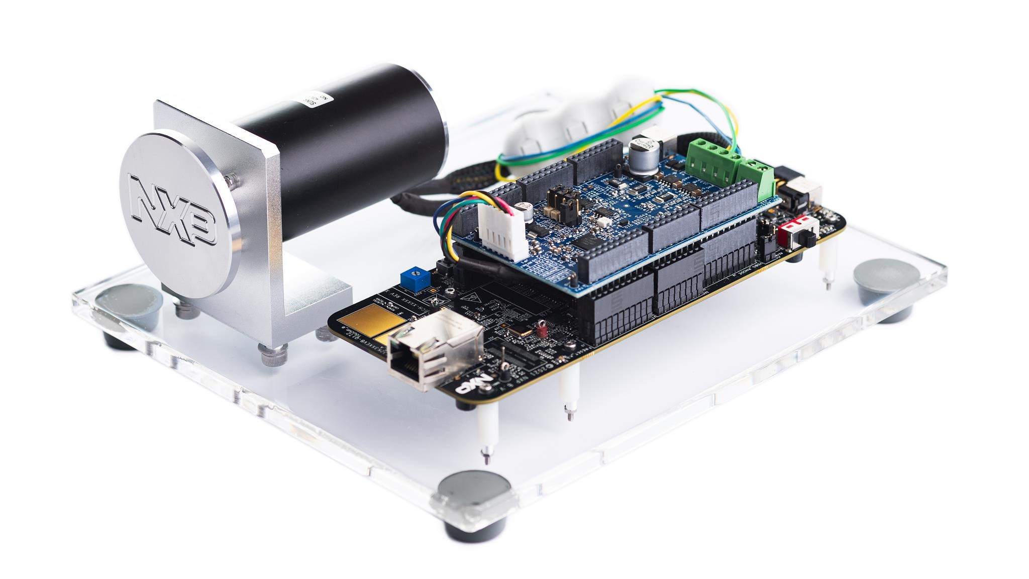
The NXP MCSPTE1AK344 development kit provides an easy-to-use platform for evaluating and prototyping automotive brushless direct current (BLDC) and permanent magnet synchronous motor (PMSM) motor control applications. Based on the S32K344 microcontroller and GD3000 pre-driver, the kit helps you begin development before the final hardware is available.
This guide walks you through the process of setting up the MCSPTE1AK344 development kit, installing the required software, connecting the hardware, building and debugging the application project, and using FreeMASTER with the Motor Control Application Tuning (MCAT) tool to run and tune the motor.
1.2 Get to Know the MCSPTE1AK344 Motor Control Development Kit
Review each visual below to familiarize yourself with all of the components of the kit's parts.

1.3 Get to Know the S32K344 Evaluation Board
The diagram below locates and identifies components of the S32K344 evaluation board.

1.4 Get to Know the DEVKIT-MOTORGD
Labeled below are the components for the DEVKIT-MOTORGD.

1.5 Header/Pinout for PMSM Motor Control
The S32K344EVB controls the DEVKIT-MOTORGD through the inner pins of the I/O headers, which are Arduino compatible.
Below you will find the pin configuration for the PMSM motor control with the configurable pins indicated in red.

1.6 Header/Pinout for BLDC Motor Control
The S32K344EVB controls the DEVKIT-MOTORGD through the inner pins of the I/O headers, which are Arduino compatible.
Below you will find the pin configuration for the BLDC motor control with the configurable pins indicated in red.

2. Get Software
To access the software (SW) for this development kit, you will sign in at NXP.com with your credentials.
2.1 Download SW packages from Automotive Software Package Manager
First, you will open the Automotive Software Package Manager and select option "S32K3" under "General-Purpose MCUs".

Expand the "FRDM Automotive Board Installation Package" bundle and check the boxes for "S32 Design Studio", "Real-Time Drivers" and "FreeMASTER" software (other packages are optional).

Click the "Generate Bundle Installer" button at the end of the page.

Next you will go through accepting the Export Control and SW License Agreement. Review and scroll all the way to the bottom where you will accept the terms. Once you have accepted the terms, you will close the wizard to proceed with installation. Installer and Installer User Manual download will start automatically in a few moments.

To simplify the installation process for the FRDM Automotive Board Installation Package SW bundle, the installation and configuration is automated.

2.2 Add GNU Compiler Collection (GCC) Toolchain Version 10.2
Because the latest versions of S32 Design Studio only include GCC toolchain version 11.4., you will need to install version 10.2, which is compatible with Real-Time Drivers (RTD).
In S32 Design Studio, from the top menu, go to Help $rarr; S32DS Extensions and Updates. In the S32DS Extensions and Updates dialog, you will install GCC toolchain version 10.2.

For access to the optional SW go to S32 Design Studio and from the top menu, select Help → S32DS Extensions and Updates. In the S32DS Extensions and Updates dialog, click Add Update Sites.
Alternatively, you can drag the downloaded update site file and drop it into the S32DS Extensions and Updates dialog. The added software package will be automatically selected for installation.

2.3 Get FreeMASTER Application Tool for Real-Time Debugging
Download and install the FreeMASTER application tool for real-time debugging.

2.4 Get Automotive Math and Motor Control Library (AMMCLib) Set
Download and install AMMCLib for S32K3xx.


2.5 Download the Development Kit Application Software
Download and install the MCSTE1AK344 motor control application software package.


2.6 Elektrobit tresos Studio and Standalone RTDs (Optional Step for AUTOSAR Examples)
- Download and install Elektrobit tresos Studio / AUTOSAR® Configuration Tool from S32K3 Standard Software Package
- Download and install the .exe file of the S32K3 Real-Time Drivers for Cortex-M from the S32K3 Standard Software Package


To save configuration time, select the EB tresos installation directory when prompted.
If you installed RTD prior EB tresos, create a SW32K3_S32M27x_RTD_R23-11_7.0.0_QLP03.link file in C:\EB\tresos\links folder with the content: "path=C:/NXP/SW32K3_S32M27x_RTD_R23-11_7.0.0_QLP03".

3. Plug It In
This section will walk you through how to set up connections.
3.1 Check the Default Jumper Positions in the MCSPTE1AK344 Development Kit
Reference the charts and diagrams below for set-up of the development kit jumpers.

| S32K3X4EVB-T172 Default Jumper Settings | ||
|---|---|---|
| Jumper | State | Notes |
J1 |
CLOSED | Disabled FS26 watchdog after power-up |
J5 |
1-2 | Select voltage level for FS26 DEBUG pin |
J8 |
CLOSED | External circuits powered from VDD_HV_B domain |
J9 |
CLOSED | External circuits powered from VDD_HV_A domain |
J427 |
CLOSED | The MCU peripherals powered from the VDD_HV_A domain |
J15 |
CLOSED | The MCU peripherals powered from the VDD_HV_B domain |
J18 |
1-2 | 5 V for the VDD_HV_A domain |
J13 |
1-2 | 3.3 V for the VDD_HV_B domain |
J20 |
OPEN | LIN1 Commander* mode |
J22 |
1-2 | 5 V from FS26 SBC |
J24 |
OPEN | LIN2 Commander* mode |
J26 |
CLOSED | 3.3 V from FS26 SBC |
J30 |
OPEN | FS26 wake inputs |
J31 |
1-2 | V15 domain powered from FS26 SBC |
J44 |
OPEN | On-board debugger UART pins |
J423 |
CLOSED | 12 V from J14 connector |
J424 |
CLOSED | Connect 3.3 V voltage signal with 3.3 V MCU power domain option |

| S32K3X4EVB-Q172 Default Jumper Settings | ||
|---|---|---|
| Jumper | State | Notes |
J1 |
CLOSED | Disabled FS26 watchdog after power-up |
J5 |
1-2 | Select voltage level for FS26 DEBUG pin |
J8 |
CLOSED | External circuits powered from VDD_HV_B domain |
J9 |
CLOSED | External circuits powered from VDD_HV_A domain |
J10 |
CLOSED | The MCU peripherals powered from the VDD_HV_A domain |
J18 |
1-2 | 5 V for the VDD_HV_A domain |
J20 |
OPEN | LIN1 Commander* mode |
J22 |
1-2 | 5 V from FS26 SBC |
J24 |
OPEN | LIN2 Commander* mode |
J26 |
CLOSED | 3.3 V from FS26 SBC |
J30 |
OPEN | FS26 wake inputs |
J44 |
OPEN | On-board debugger UART pins |
3.2 Set Up Jumpers in the DEVKIT-MOTORGD Evaluation Board
Reference the charts and diagrams below for set-up of the evaluation board jumpers.
| Jumper | Setting | Option | Description |
|---|---|---|---|
J8 |
Short | HALL/Encoder interface | Voltage level for HALL/Encoder interface is 3.3 V |
| Open | Voltage level for HALL/Encoder interface is 5.0 V (default) | ||
J9/J10/J11
|
1-2 | Motor Type | Bidirectional 3-phase current sensing for PMSM FOC (sinusoidal) motor control |
| 2-3 | 3-phase back-EMF voltage sensing for BLDC six-step (trapezoidal) sensorless motor control |
Place DEVKIT-MOTORGD jumpers J9, J10 and J11 into position 1-2 for PMSM application or 2-3 for BLDC application. Jumper J8 stays open for 5 V HALL sensors.


Make sure that the potentiometer for overcurrent comparator is set in the correct position (approximately 8 - 10 A, slightly to the left from the middle).

3.3 Connect the Motor
Ensure that the motor phase wires are in the following order, from phase A to phase C:
A: Yellow
B: Green
C: Blue

3.4 Connect the Power Supply
Switch SW1 to the OFF position (fully to the left).

Connect the 12 V power supply adapter.

Switch SW1 to the ON position (fully to the right).

When power is applied to the EVB, four orange LEDs next to the voltage regulators indicate that the 12 V, 5 V, 3.3 V and 1.5 V supply voltages are present.

4. Build the Application Project
Let's take your MCSTE1AK344 motor control kit for a test drive.
4.1 Select Application and MCU Programming
Select the appropriate PMSM or BLDC motor control application from the installed directory NXP\MC_DevKits\MCSPTE1AK344\sw.
To import the installed application software project in the S32 Design Studio IDE for S32 Platform:
- Launch S32DS for S32 Platform
- Go to File → Import then select General rarr; Existing Projects into Workspace
- Find the installed application directory:
NXP\MC_DevKits\MCSPTE1AK344\swand choose the corresponding project and click "OK". Then, click "Finish"


4.2 Use Configuration Tool
If you selected a project with low-level drivers (ll in project name), follow these steps:
- Expand the imported project folder in S32 Design Studio, such as
MCSPTE1AK344_PMSM_FOC_2Sh_ll. Then, double-click the corresponding *.mex file to open the project configuration in the Configuration Tool - After confirming that you configured the correct project, click "Update Code" button for generating configuration files


If you selected a project with AUTOSAR drivers (with as_tr in the project name), the S32DS project will contain a tresos folder with EB tresos configuration. Follow the following steps.
- Open EB tresos Studio and import the appropriate subfolder
- In EB tresos Studio, double-click on ECU (CORTEXM, S32K3XX) and generate the project (Menu → Project → Generate Project)

4.3 Upload Software and Debug
To upload the SW and debug, follow the following steps.
- In S32DS, return back to the C/C++ perspective
- Go to the Debug Configuration menu and select the predefined debug configuration for building and uploading software onto the MCU
- The S32DS will switch into debug perspective. Click Resume or press F8 to run the code. Then, click Disconnect to avoid interference between the S32 Design Studio debugger and the FreeMASTER tool


4.4 Set Up the Debugging Tool
Launch the FreeMASTER application to set up the debugging tool. To open the FreeMASTER project, select File → Open Project, then browse to the FreeMASTER_control folder in the selected project directory and open the *.pmpx file.

To enable communication, access the FreeMASTER toolbar and click Go (or press Ctrl+G). You will know that communication has been successfully activated when you see the following at the bottom of the status bar:
RS-232; port=COMn; speed = 115200

Application Control
Application Setup (optional step)
If you run the MCSPTE1AK344 software on modified or custom hardware, you may need to edit hardware scales and fault triggers in the Motor Control Application Tuning (MCAT) tool.
Open the Application Setup page and edit the values on the left side of the page.

Once you finish, click "Save config" to generate a static configuration file. You may check file content at the "Output file" page.
Next, repeat the step from the Upload Software and Debug section to build the project and upload the code into MCU.
Motor parametrization and control loops autotuning (optional step)
In a case of motor change, you may benefit from new MCAT 2.0 motor parametrization and control loops autotuning features.
On the Motor Parameters page, enter the four basic motor parameters that cannot be detected automatically:
- Number of pole pairs
- Nominal Current
- Nominal Speed
- Maximum Speed
Click "Update Target" to start motor-parameter estimation and automatic control-loop tuning. The parameters are typically updated automatically in less than one minute.

Run the Motor
Open the "Speed Loop" page, then use the "Speed Control" tab to set the required speed and turn on the motor drive.

Select one of the predefined Scopes or Recorders in Project Tree to watch the application variables in real time.
For runtime debugging, you can create or modify scopes and recorders as needed.

Check Pending Faults
If there are pending faults and the red LED indicates a fault state, click "CLEAR" on the MCAT Control tab. You can also press SW5 and SW6 simultaneously on the board.

Start Application
Click "On/Off" on the control bar, or press SW5 or SW6 on the board, to start clockwise or counterclockwise rotor rotation. The blue LED indicates the running state.
Set Speed
Modify the "Required Speed" field on the control bar, or change the "Speed Required" value in the Variable Watch window. You can also control the speed by pressing SW5 or SW6 on the board.

Stop Application
Stop the motor by clicking "On/Off" on the MCAT control page, clearing the On/Off variable, or pressing and holding SW5 and SW6 on the S32K344EVB board. The green LED indicates the ready state.
Design Resources
Board Information
Chip Information
-
AN13767 3-Phase Sensorless PMSM Motor Control Kit with S32K344 Using RTD Low Level API Application Note
-
AN13884 3-Phase Sensorless PMSM Motor Control Kit with S32K344 Using RTD AUTOSAR® API
-
AN13902 3-Phase Sensorless PMSM Motor Control Kit with S32K344 Using MBDT Blocks
-
AN12881 Motor Control Using FreeRTOS
Chip Documents
- Motor Control Solutions Based on S32K3 MCUs Brochure
- S32K3 Arm Cortex-M7-Based Automotive MCUs: Brochure
-
S32K3xx MCU Family - Reference Manual
-
Mask Set Errata for Mask 0P55A/1P55A - Errata
- MC33GD3000, Three Phase Field Effect Transistor Pre-Driver - Data Sheet
- FS26, Safety System Basis Chip with Low Power for ASIL D /ASIL B - Product Brief
Software
-
MCSPTE1AK344 Development Kit Application Software
-
S32K3 Standard Software Package
-
S32K3 Reference Software Package
- S32 Design Studio IDE
- Real-Time Drivers (RTD)
- S32K Power Estimation Tool (PET)
- Model-Based Design Toolbox (MBDT)
- Structural Core Self-Test (SCST) Library
- FreeMASTER Run-Time Debugging Tool
- Inter-Platform Communication Framework (IPCF)
- Automotive Math and Motor Control Library (AMMCLib)
- S32 Safety Software Framework (SAF) and Safety Peripheral Drivers (SPD)
Support
Training
Forums
Connect with other engineers and get expert advice on designing with the MCSPTE1AK344 on one of our community sites.
On this page
- 1.1
Introduction
- 1.2
Get to Know the MCSPTE1AK344 Motor Control Development Kit
- 1.3
Get to Know the S32K344 Evaluation Board
- 1.4
Get to Know the DEVKIT-MOTORGD
- 1.5
Header/Pinout for PMSM Motor Control
- 1.6
Header/Pinout for BLDC Motor Control
- 2.1
Download SW packages from Automotive Software Package Manager
- 2.2
Add GNU Compiler Collection (GCC) Toolchain Version 10.2
- 2.3
Get FreeMASTER Application Tool for Real-Time Debugging
- 2.4
Get Automotive Math and Motor Control Library (AMMCLib) Set
- 2.5
Download the Development Kit Application Software
- 2.6
Elektrobit tresos Studio and Standalone RTDs (Optional Step for AUTOSAR Examples)
- 3.1
Check the Default Jumper Positions in the MCSPTE1AK344 Development Kit
- 3.2
Set Up Jumpers in the DEVKIT-MOTORGD Evaluation Board
- 3.3
Connect the Motor
- 3.4
Connect the Power Supply
- 3.5
Connect the Debug Interface
- 4.1
Select Application and MCU Programming
- 4.2
Use Configuration Tool
- 4.3
Upload Software and Debug
- 4.4
Set Up the Debugging Tool