Getting Started with the MPC5775E-EVB
Contents of this document
-
Out of the Box
-
Get Software
-
Plug It In
-
Build, Run
Sign in to save your progress. Don't have an account? Create one.
Purchase your MPC5775E 3-phase PMSM Development Kit
1. Out of the Box
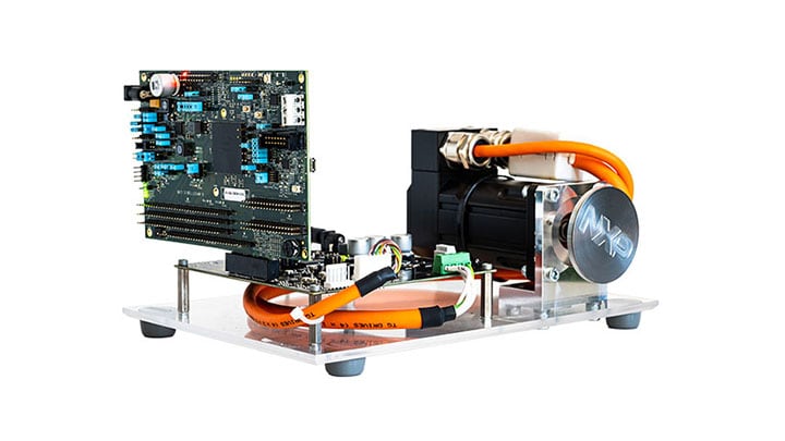
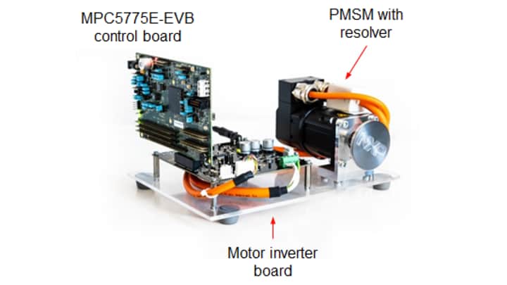
1.1 Get to Know the Development Kit
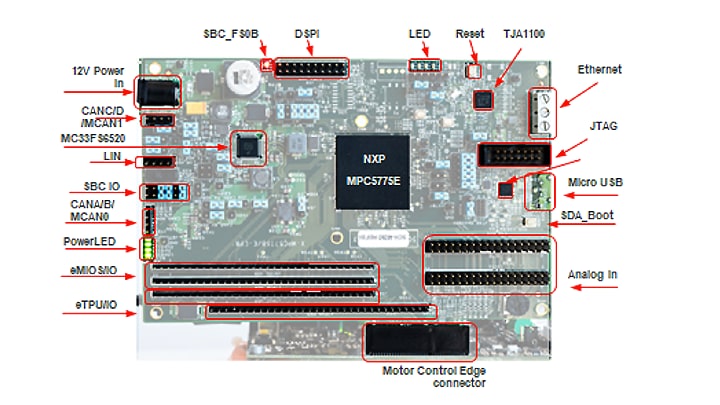
1.2 Get to Know the MPC5775E-EVB Control Board
MPC5775E-EVB is powered from 3-phase low-voltage power stage. In standalone operation MPC5775E-EVB requires 12 V external DC power supply. It includes a MC33FS6520LAE system basis chip (SBC) for the board power supply. Also features a debug selectable between external debug connection via JTAG or on-board OpenSDA(USB interface), headers available for eMIOS, ADCs, DSPI, eTPU and motor control connector (PCIe X4 style edge connector) modules.
MPC5775E-EVB control board communication features:
- SBC CAN physical interface (selectable
J48/J50between FlexCAND /MCAN1 [GPIO246 and GPIO247] or FLEXCANC [GPIO87 and GPIO88]) - Option to select CAN termination
J49 - SBC LIN physical interface connected to RXDC/TXDC (
J51/J54connected by default) - Leader or follower mode supported (
J52VSUP connection) - TJA1145T/FD CAN physical interface (selectable between FlexCANA /MCAN0 GPIO83 and GPIO84] and FlexCANB [GPIO85 and GPIO86])
- TJA1100 automotive Ethernet PHY (physical interface)
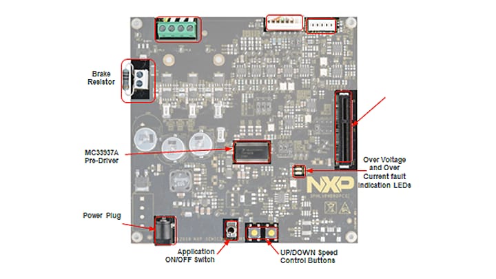
1.3 Get to Know the 3-phase Low Voltage Power Stage Board
3-phase low-voltage power stage board features a SMARTMOS® MC33937A intelligent mos-fet gate driver with 12 - 24 VDC input power supply voltage range, reverse polarity protection, resolver excitation generator and resolver feedback signals processing, encoder and Hall sensor, and a phase current and DC bus current measurement by shunt resistors, DC-bus overvoltage, overcurrent and undervoltage fault detection.
It also has a breaking resistor, DC/DC power supply for gate driver and auxiliary circuits and control buttons, plus galvanically isolated SPI (not populated), OC/OV protection and a power plug PWM 3-phase outputs.
2. Get Software
2.1 Download the MCSPTR2A5775E Development Kit – Quick Start Package
The software package includes the software projects for most typical hardware configurations.
2.2 Get the Integrated Development Environment (IDE)
MCSPTR2A5775E development kit performs better when using S32 Design Studio IDE for Power Architecture®.
2.3 Get the Run-time Debugging Tool
MCSPTR2A5775E development kit performs better when using the FreeMASTER tool for run-time debugging.
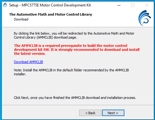
2.4 Get the Adapter Installation Software
MCSPTR2A5775E development kit performs better when using OpenSDA bootloader and application.
3. Plug It In
You can watch the video or follow the below step-by-step guide to set up your MCSPTR2A5775E:
3.1 Set Up Jumpers in MPC5775E-EVB Control Board
| Jumper | Setting | Option | Description |
|---|---|---|---|
J11 |
1-2 | SDADC supply voltage | VDDA_SD = VREF_A |
J14 |
1-2 | SDADC supply voltage | VREF_A |
J28 |
2-3 | VDDEHX I/O supply voltage (medium I/O pads) |
5 V |
J29 |
1-2 | RAM standby supply voltage VSTBY |
Short to ground |
J30 |
Open | Fault 1 from MC pCIE to IRQ0 | to eMIOS14 header, when using eMIOS header short J30 |
J31 |
Open | Fault 2 from MC pCIE to IRQ1 | to eMIOS15 header, when using eMIOS header short J31 |
J41 |
1-2 | VDDIO Input voltage for MISO output buffer |
Allows voltage compatibility with MCU I/ Os 5 V default |
J67 |
1-2 | BOOT_CFG1 | Booting configuration: BOOT_CFG1-- 0: Boot from internal flash memory (Default) 1: Boot from FlexCAN or eSCI interface |
J74 |
1-2 | LED supply voltage | User LED headers supply voltage definition |
3.2 Set Up Jumpers in PowerSBC Board
| Jumper | Setting | Option | Description |
|---|---|---|---|
J44 |
Open | FCRBM | Feedback core resistor bridge monitoring signal to GND |
J45 |
1-2 | SBC_VPRE to SBC_DEBUG | Configuration PowerSBC mode. When populated, PowerSBC is in debug mode. |
J46 |
Open | SBC_INT_B SBC_RST_B |
The main function is to reset the MCU when the safety block reports a failure |
J48 |
1-2 | SBC_CAN_RXD | CAN1 RX header |
J49 |
1-3 2-4 |
SBC_CANH SBC_CANL |
CANH/L termination resistor GND |
J50 |
1-2 | SBC_CAN_TXD | CAN1 TX header |
J51 |
1-2 | RXDL | LIN RX header |
J52 |
1-2 | LIN | LEADER/FOLLOWER |
J54 |
1-2 | TXDL | LIN TX header |
J55 |
1-2 | RST | Ethernet TJA110 reset |
J58 |
1-2 | FLEXCAN_RXA | RXD TJA1145T |
J60 |
1-2 | FLEXCAN_TXA | TXD TJA1145T |
J119 |
1-2 4-5 7-8 10-11 13-14 |
JTAG | Use this header setting for JTAG debugging (aligned to JTAG connector) |
J127 |
2-3 | RXD2 | PHY registered as Leader |
3.3 Set Up Jumpers in 3-phase Low-voltage Power Stage Board
| Jumper | Setting | Option | Description |
|---|---|---|---|
J5 |
1-2 2-3 |
Resolver feedback | Resolver S4 output enters operational amplifier (default) DC offset compare value |
J6 |
1-2 2-3 |
Resolver feedback | Resolver S4 output enters operational amplifier (default) DC offset compare value |
J7 |
2-3 1-2 |
Resolver | Resolver excitation - square signal (default) Resolver excitation - SWG source |
J9 |
1-2 2-3 |
DC-bus Current Measurement | By an external operational amplifier (default) By a MC33937 |
J10 |
1-2 2-3 |
Overcurrent threshold reference | +5V DC V_ref |
J11 |
1-2 2-3 |
Overcurrent fault | External comparator (default) MC33937 output |
J16 |
2-3 1-2 |
Zero-Cross Detection |
Default: not populated Zero-cross signal from MC33937 Encoder / Hall sensors - PhA |
J17 |
2-3 1-2 |
Zero-Cross Detection |
Default: not populated Zero-cross signal from MC33937 Encoder / Hall sensors - PhB |
J18 |
2-3 1-2 |
Zero-Cross Detection |
Default: not populated Zero-cross signal from MC33937 Encoder / Hall sensors - PhC |
J19 |
1-2 | Phase Current measurement | By an external operational amplifier (default) PhA |
J20 |
1-2 | By an external operational amplifier (default) PhB | |
J21 |
1-2 | By an external operational amplifier (default) PhC |
3.4 Configure MPC5775E-EVB Evaluation Board
Ensure jumper J119 is configured for using JTAG interface.
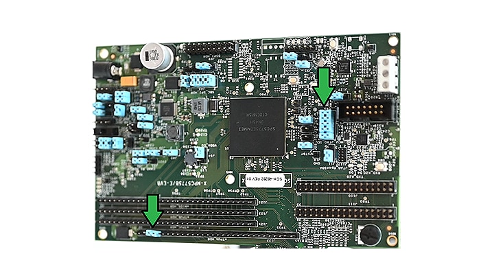
The default configuration is for using open SDA. Also make sure to use a jumper to short pins 28 and 29 on J122.
Debug interface selection:
| Open SDA | JTAG | |
|---|---|---|
J119 |
2-3 | 1-2 |
| 5-6 | 4-5 | |
| 8-9 | 7-8 | |
| 11-12 | 10-11 | |
| 14-15 | 13-14 |
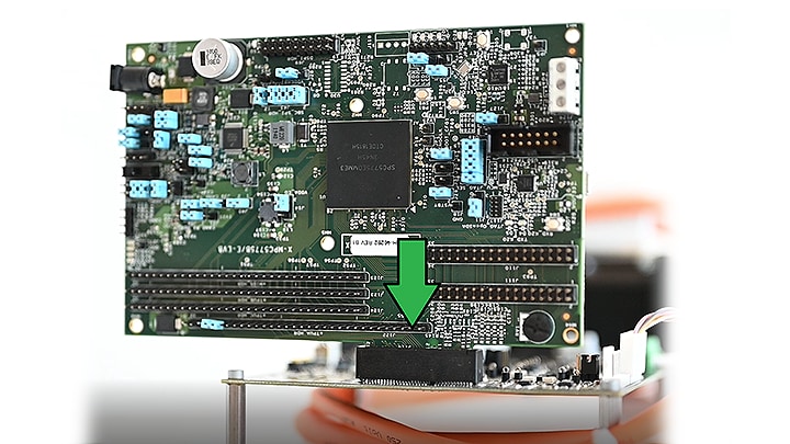
3.5 Plug the MPC5775E-EVB Into the Power Stage Board
Use the PCIe connector J114 on the MPC5775E-EVB to plug the board into the power stage connector J14.
Make sure all the jumpers at the power stage board are in default configuration:
Power board default jumper configuration:
| Jumper | Setting |
|---|---|
J5 |
1-2 |
J6 |
1-2 |
J7 |
2-3 |
J9 |
1-2 |
J10 |
2-3 |
J11 |
1-2 |
J16 |
Open |
J17 |
Open |
J18 |
Open |
J19 |
1-2 |
J20 |
1-2 |
J21 |
1-2 |
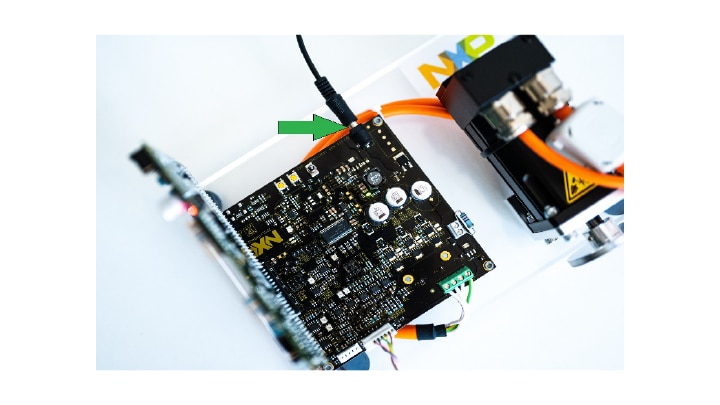
3.6 Plug in the Power Supply
Connect the 24 V power supply for powering the MPC5775E-EVB and DEVKIT-MOTORGD boards, together with the 3-phase PM motor. MPC5775E-EVB is configured to be powered from DEVKIT-MOTORGD board.
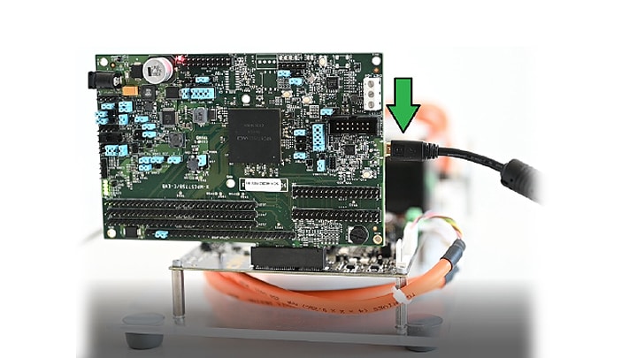
3.7 Connect the USB Cable
Connect MPC5775E-EVB to the PC using the USB cable to enable real-time debugging via FreeMaster.
3.8 Connect the JTAG/NEXUS Cable
Connect the JTAG/NEXUS debugger cable to load the project into MCU.
4. Build, Run
Let's take your MCSPTR2A5775E development kit for a test drive.
4.1 Import the Project to IDE
Import the installed application software project in the S32 Design Studio for power architecture. Launch S32DS and then click File > Import and then select General > Existing Projects into Workspace.

Navigate to the installed application directory: MC_DevKits\MCSPTR2A5775E\sw\ and click OK, then Finish.

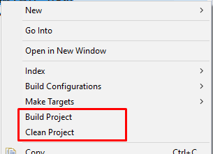
4.2 Build the Project – OPTIONAL
- Right click on the imported project and select Clean
- Right click on the imported project and select Build
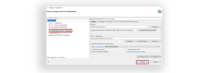
4.3 Debug for Loading Code Into MCU
In the S32 Design Studio menu, click Run > Debug Configuration and select the predefined debug configuration and click on Debug to start loading built code into MCU.
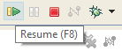
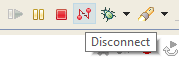
4.4 Let Code Run and Disconnect
Let code run by clicking on the Resume (F8) button, and use Disconnect button for avoiding interference between S32DS debugger and FreeMASTER tool.
4.5 Debug Your Motor Control Application Using a Debugger Tool
Start the FreeMASTER project for debugging by launching FreeMASTER and then open *.pmp file from the folder <selected project>\FreeMASTER_control by clicking File > Open Project...

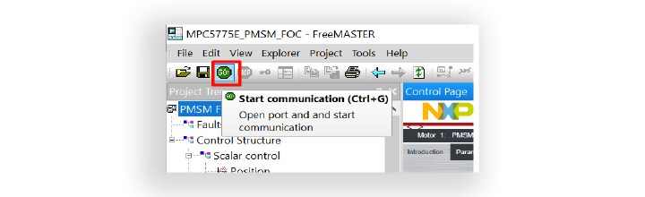
4.6 Start a Connection With the MPC5775E MCU
Click the green GO button in the FreeMASTER toolbar or press <CTRL +G> to enable the communication.
Successful communication is signalized in the status bar at very bottom as: RS232 UART Communication;COMn; speed = 115200
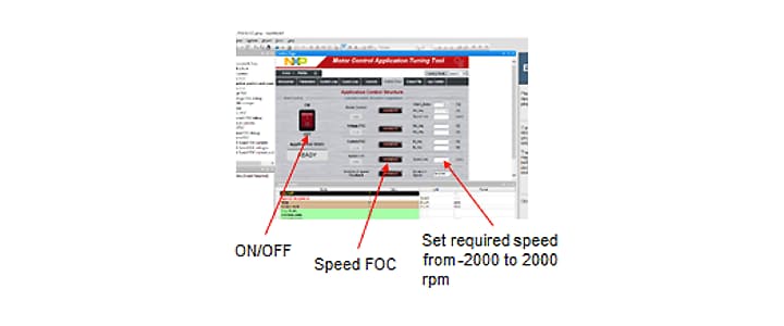
4.7 Control Your Motor
Click App Control tab in the motor control application turning (MCAT) tool menu to display the application control page. Configure the motor rpms and turn on the motor drive.
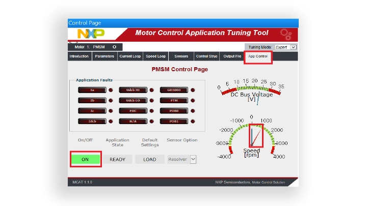
Success, motor runs.
Start Your Application
-
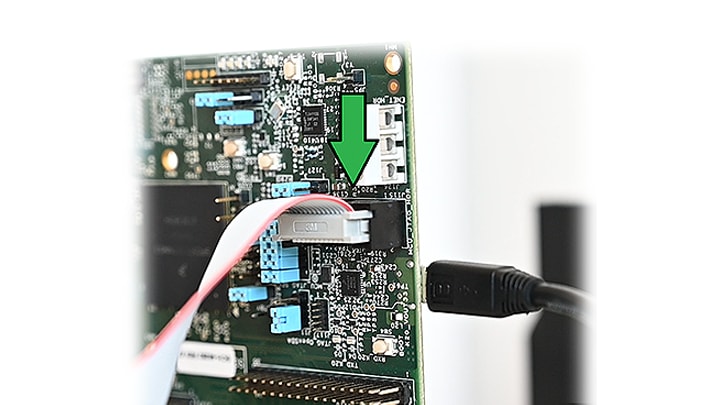
Connect the micro USB cable to
J116(bottom side) if not already connected.If necessary, install the driver to make the COM port available as an OpenSDA port, which can be checked under COM and LPT ports in the device manager.
-
Go to the device manager and right click the COM port detected and select Update Driver Software.
Select Browse My Computer for driver software and select the OpenSDA driver that has been downloaded.
Restart your machine.
-
Connect power supply 24 V to the inverter and micro USB cable to micro USB port on the development board.
Turn on the power switch.
-
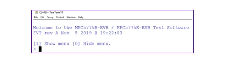
Open Tera Term on Windows PC and select the serial port to which the micro USB of the development board is connected and click OK
Go to Setup > Serial Port and select 19200 as the baud rate.

-
After resetting the board by pressing the reset button (
SW1)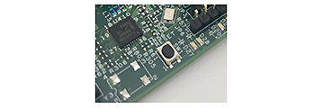
You will be able to see this welcome message on the terminal:
-
Run the Device Manager on your system.
Check which COM port was assigned to the OpenSDA – CDC Serial Port.
-
The power stage cannot be powered without the controller board when Brake Resistor (
J2) is populated.The absence of the controller board leads to a high BRAKE_GATE signal, and a large current flows through the BRAKE_RESISTOR, creating a considerable burn hazard as the resistor will dissipate enough heat to harm on contact. If PWM braking is used, software must explicitly control the BRAKE_GATE signal. Thus, the power stage board must always be connected to the controller board.
- Connect the micro USB cable to the MCSPTR2A5775E controller board and the host PC.
- Connect the controller board to the power stage using PCIe connector
J1. - Connect the 24 V power supply to the power stage. The controller board power supply is taken from the power stage.
-
Start the FreeMASTER project MCSPTR2A5775E.pmp located in MCSPTR2A5775E_Z7_0\ FreeMASTER_control project directory.
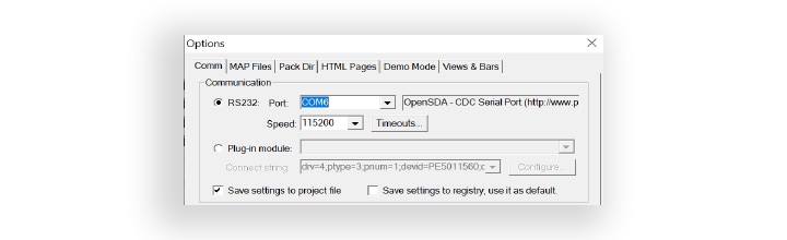
Click on Project\Options menu, choose the RS232 COM port number that was assigned to the virtual COM port driver and set the communication speed to 115200 Bd.
Enable communication by pressing the START button in FreeMASTER or by pressing <CTRL+K>.
-
Start the application by pressing 1 - “RUN” on the flip/flop (ON/OFF) switch on the FreeMASTER control page, or by positioning the RUN/STOP switch (
SW1on the power stage board) to the RUN position (transition from STOP to RUN in case the switch was in the RUN state when a fault event occurred).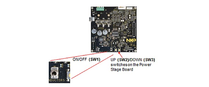
-
Stop the application by pressing 0 - “STOP” on the flip/flop (ON/OFF) switch on the FreeMASTER control page, or by positioning the RUN/STOP switch (
SW1on the power stage board) to the STOP position.
Design Resources
Board Documents
Chip Documents
Support
Forums
Connect with other engineers and get expert advice on designing with the MCSPTR2A5775E on one of our community sites.
On this page
- 1.1
Get to Know the Development Kit
- 1.2
Get to Know the MPC5775E-EVB Control Board
- 1.3
Get to Know the 3-phase Low Voltage Power Stage Board
- 2.1
Download the MCSPTR2A5775E Development Kit – Quick Start Package
- 2.2
Get the Integrated Development Environment (IDE)
- 2.3
Get the Run-time Debugging Tool
- 2.4
Get the Adapter Installation Software
- 3.1
Set Up Jumpers in MPC5775E-EVB Control Board
- 3.2
Set Up Jumpers in PowerSBC Board
- 3.3
Set Up Jumpers in 3-phase Low-voltage Power Stage Board
- 3.4
Configure MPC5775E-EVB Evaluation Board
- 3.5
Plug the MPC5775E-EVB Into the Power Stage Board
- 3.6
Plug in the Power Supply
- 3.7
Connect the USB Cable
- 3.8
Connect the JTAG/NEXUS Cable
- 4.1
Import the Project to IDE
- 4.2
Build the Project – OPTIONAL
- 4.3
Debug for Loading Code Into MCU
- 4.4
Let Code Run and Disconnect
- 4.5
Debug Your Motor Control Application Using a Debugger Tool
- 4.6
Start a Connection With the MPC5775E MCU
- 4.7
Control Your Motor