Getting Started with FRDM-KW41Z
Contents of this document
-
Plug It In
-
Get Software
-
Build, Run
-
Create
Sign in to save your progress. Don't have an account? Create one.
Purchase your FRDM-KW41Z | KW41Z/31Z/21Z | Wireless
1. Plug It In
Let's take your FRDM-KW41Z for a test drive! You have the choice of watching the sequence in a short video or following the detailed actions list below.
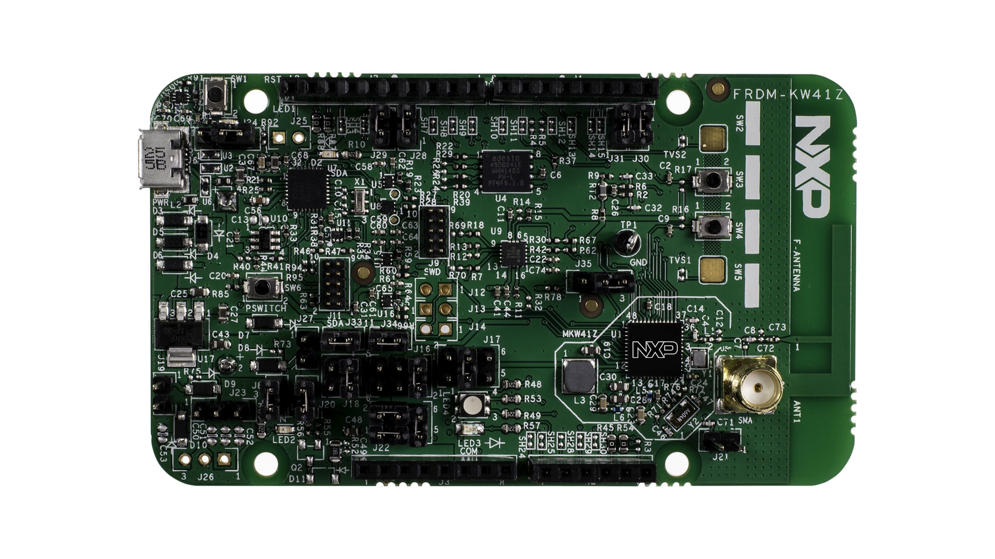
1.1 Getting Started with the FRDM-KW41Z Development Board
1.3 Run the Out-of-Box Demo
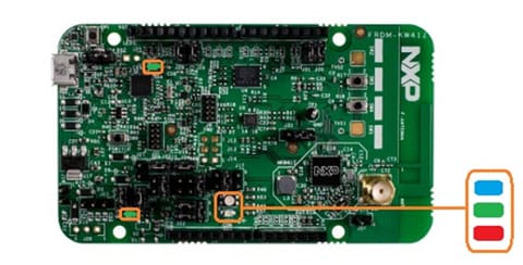
Your FRDM-KW41Z comes loaded with a demo that flashes the multicolored LEDs when you connect the board. If you do not see the LEDs flashing, first unplug and replug in the board. If that does not resolve the issue, try contacting us through the NXP Community .
2. Get Software
Choose a Development Path:
MCUXpresso Software Development Kit (SDK) + Integrated Development Environment (IDE)
- True debug support via SWD and JTAG
- High software flexibility
- Full set of peripheral drivers with source
- Application examples and project files
Zephyr™ OS
- A scalable, open source real-time operating system (RTOS)
- Supports multiple hardware architectures
- Optimized for resource constrained devices
- Built with security in mind
Arm Mbed Online Development Site
- Online compiler, no SWD or JTAG debug
- Simple, heavily abstracted programming interface
- Useful but limited drivers with source
- Community-submitted examples
2.1 Installing Software for the FRDM-KW41Z
2.2 Download MCUXpresso SDK with Connectivity Software
MCUXpresso SDK for the FRDM-KW41Z includes all the wireless connectivity stacks required to develop your solution using Thread, IEEE 802.15.4, Generic FSK, and Bluetooth Low Energy.
Click below to download a preconfigured SDK release for the FRDM-KW41Z that includes all the wireless connectivity stacks for the KW41Z.

You can also use the online SDK Builder to create a custom SDK package for the FRDM-KW41Z using the SDK builder.
2.3 Install Your Toolchain
NXP offers a complimentary toolchain called MCUXpresso IDE.

Want to use a different toolchain?
No problem! MCUXpresso SDK connectivity stack software also supports IAR .

2.4 MCUXpresso Config Tools
The MCUXpresso Config Tools is an integrated suite of configuration tools that guides users in creating new MCUXpresso SDK projects, and also provides pin and clock tools to generate initialization C code for custom board support.

2.5 Terminal Configuration
Configure your preferred terminal to 115,200 baud rate, 8 data bits, no parity, and 1 stop bit. To determine the port number of the FRDM-KW41Z's virtual COM port, open the device manager and look under the "Ports" group.
Not sure how to use a terminal application? Try one of these tutorials: Tera Term Tutorial, PuTTY Tutorial.
3. Build, Run
The KW41Z Wireless Connectivity software comes with a list of demo applications and driver examples ready to be compiled and run for each connectivity stack.
Select the Connectivity Stack that you want to explore: SMAC, IEEE 802.15.4, Gen FSK or Hybrid (Bluetooth Low Energy + Thread).
3.1 Build and Run Connectivity Demos on the FRDM-KW41Z
SMAC
IEEE 802.15.4
Gen FSK
Hybrid (Bluetooth Low Energy + Thread)
3.2 Explore the Connectivity Example Codes
SMAC
The KW41Z Wireless Connectivity Software package comes with a long list of demo applications for the
SMAC protocol. To see what's available, browse to the 'examples' folder: <connectivity_software_install_folder>\boards\frdmkw41z\wireless_examples\smac.
IEEE 802.15.4
The KW41Z Wireless Connectivity Software package comes with a long list of demo applications for the
IEEE 802.15.4 protocol. To see what's available, browse to the 'examples' folder: <connectivity_software_install_folder>\boards\frdmkw41z\wireless_examples\ieee_802_15_4.
Gen FSK
The KW41Z Wireless Connectivity Software package comes with the Connectivity Test demo application
for Generic FSK protocol. To see what's available, browse to the 'examples'
folder: <connectivity_software_install_folder>\boards\frdmkw41z\wireless_examples\genfsk.
Hybrid (Bluetooth Low Energy + Thread)
The KW41Z Wireless Connectivity Software package comes with a long list of hybrid demo applications
(Thread + Bluetooth Low Energy). To see what's available, browse to the 'examples'
folder: <connectivity_software_install_folder>\boards\frdmkw41z\wireless_examples\hybrid.
Connectivity Test Application
If you are interested in running the preprogrammed Connectivity Test Application that comes with your board, click here.
3.3 Download the Bluetooth Low Energy Toolbox for your Smartphone
In order to use the Bluetooth Low Energy and Hybrid examples, the Kinetis Bluetooth Low Energy Toolbox needs to be installed on a smartphone. This application provides several examples that can be used with the connectivity stack to connect your phone to the development board over Bluetooth Low Energy.
3.4 Build, Run, and Debug Wireless Connectivity Examples
You probably want to build and debug a demo by yourself. Use the guide below to learn how to build and debug an example application from the Wireless Connectivity Stacks in the MCUXpresso IDE or IAR Embedded Workbench IDE.
SMAC
SMAC - IAR Embedded Workbench IDE
These steps show how to:
- Load and build the demo application in IAR Embedded Workbench
- Download and run the demo application
The example used below is for the SMAC Connectivity Test demo, but these steps can be applied to any of the Wireless Connectivity demo applications.
Load and build the application demo
-
Navigate to the Connectivity Test IAR workspace (located at
<install_dir>\boards\frdmkw41z\wireless_examples\smac\connectivity_test\FreeRTOS\iar)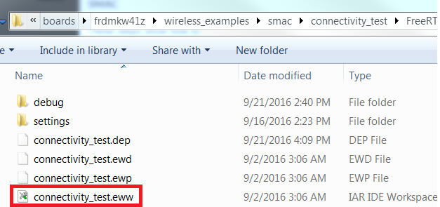
-
After the workspace is open, select the project
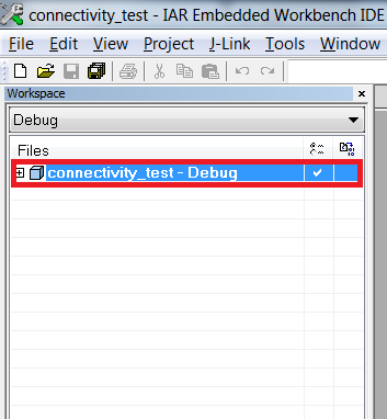
-
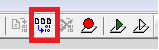
Click the Make button to build the project
Download and Run the application demo
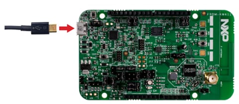
- Connect your FRDM-KW41Z board to your PC
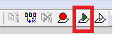
-
Click on the Download and Debug button (green arrow located on the
toolbar)
-
Once the project has loaded, the debugger should stop at main(). Open
a Terminal Emulator program and open a session to your FRDM-KW41Z
COM port. Configure the terminal with these settings:
- 115,200 baud rate
- No parity
- 8 data bits
- 1 stop bit
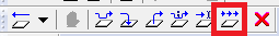
-
Click the Go button to resume operation
-
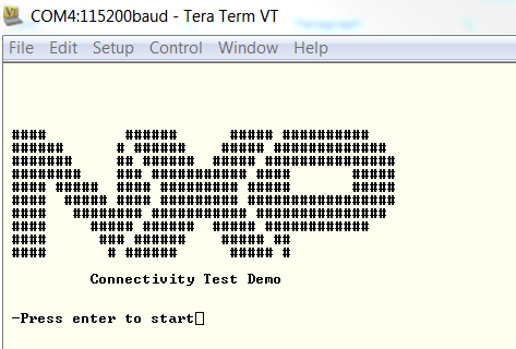
The following output will be displayed in the serial terminal. If you don't see this output, verify your terminal settings and
connections
-
Refer to
<connectivitysoftware_install_folder>\docs\wireless\SMAC\MKW41Z SMAC Demo Applications User's Guide.pdfdocument for instructions on how to run all the demo applications
SMAC - Running a demo using MCUXpresso IDE
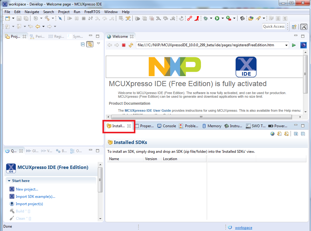
Import the MCUXpresso SDK
- Open up the MCUXpresso IDE
-
Switch to the Installed SDKs view within the MCUXpresso IDE window
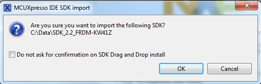
- Open Windows Explorer, and drag and drop the FRDM-KW41Z SDK (unzipped) file into the "Installed SDKs" view
-
You will get the following pop-up. Click OK to
continue the import:
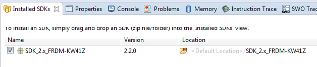
-
The installed SDK will appear in the Installed SDKs view as shown
below:
Build an Example Application
The following steps will guide you through opening the SMAC example.
-
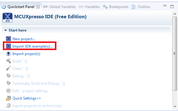
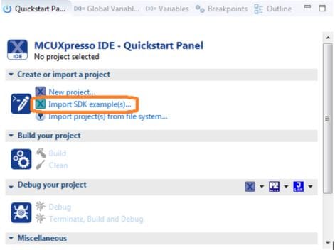
Find the Quickstart Panel in the lower left-hand corner
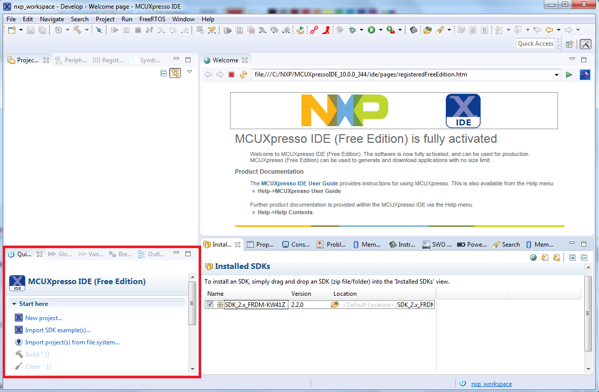
-
Then click on Import SDK examples(s)
-
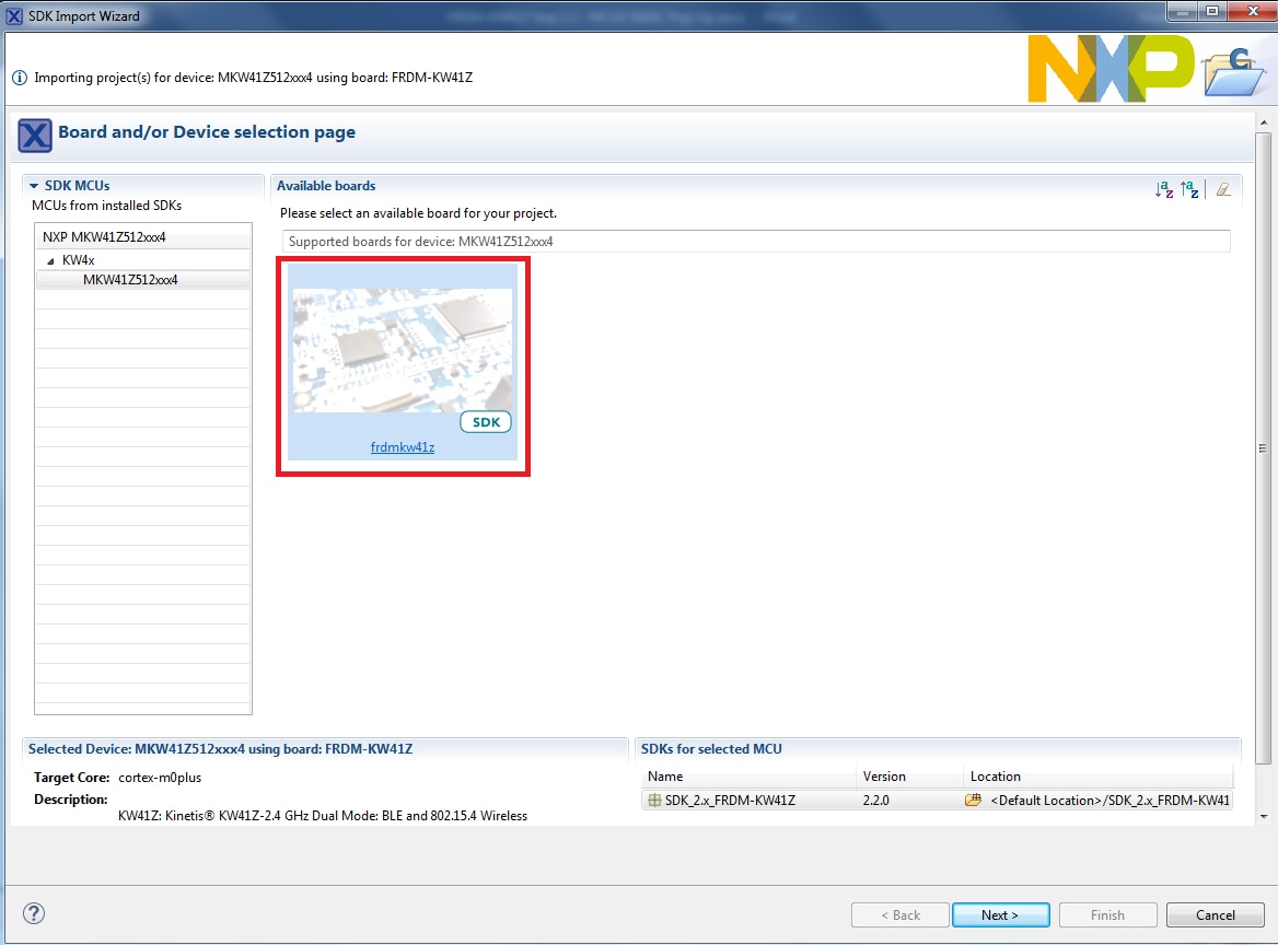
Click on the frdmkw41z board to select that you want to import an
example that can run on that board, and then click Next
-
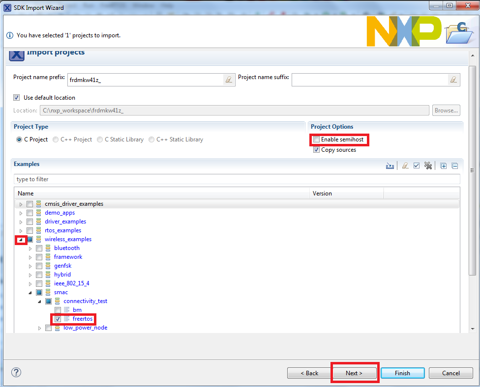
Use the arrow button to expand the "wireless_examples"
category, and then under the 'SMAC' category expand
the 'connectivity_test' project and select the
'freertos' version of the project. To use the UART for
printing (instead of the default semihosting), clear the
"Enable semihost" checkbox under the
project options. Then, click Next
-
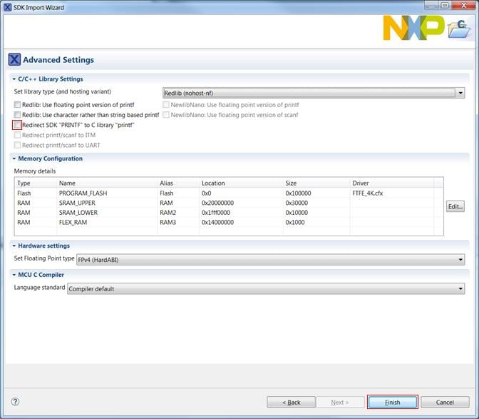
On the Advanced Settings wizard, clear the checkbox
"Redirect SDK "PRINTF" to C library
"printf"" in order to use the
MCUXpresso SDK console functions for printing instead of generic C
library ones. Then, click Finish
-
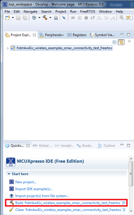
Now, build the project by clicking on the project name and then in the
Quickstart Panel click on Build
-
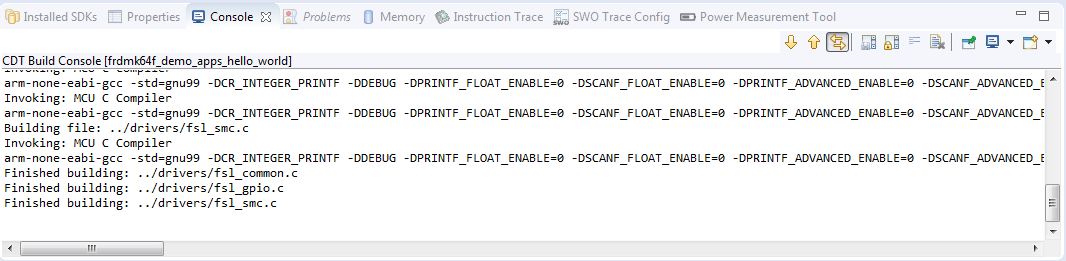
You can see the status of the build in the Console tab
Run an Example Application
- Now, that the project has been compiled, you can now flash it to the board and run it
-
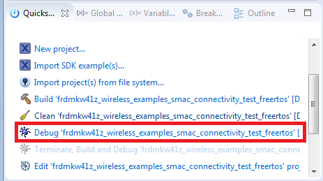
Make sure that the FRDM-KW41Z board is plugged in, and click in the
Quickstart Panel click on "Debug
'frdmkw41z_wireless_examples_smac_connectivity_test_freertos'
[Debug]"
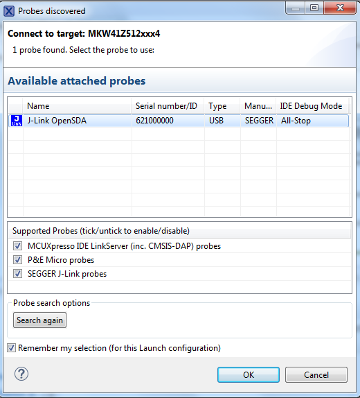
-
MCUXpresso IDE will probe for connected boards and should find the
JLink debug probe that is part of the integrated OpenSDA circuit on
the FRDM-KW41Z. Click on OK to continue
-
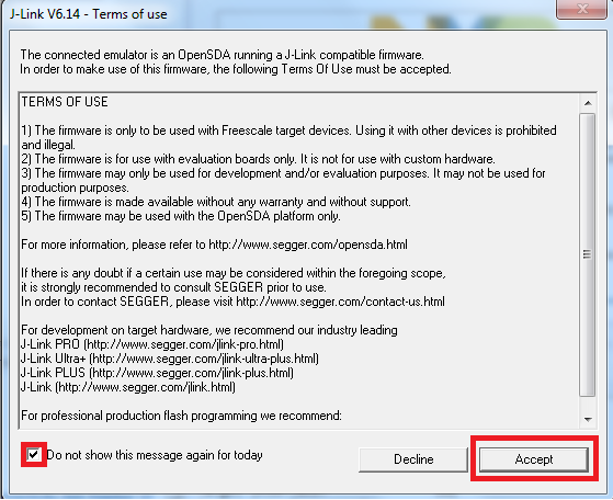
You may see the following message if this is your first debug with
JLink of the day. Click on the checkbox at the bottom not to display
the message again, and then click on Accept
-
The firmware will be downloaded to the board and the debugger started
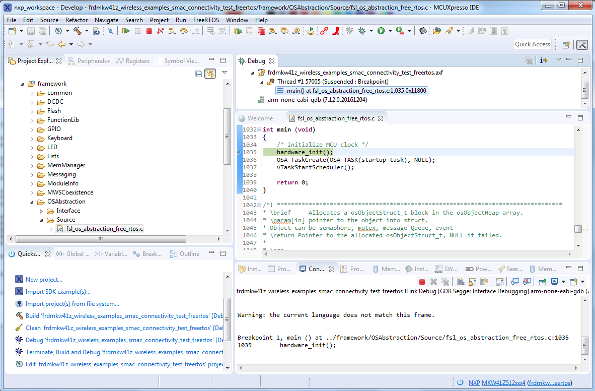
-
Hit the Terminate icon to stop the debugger

- Now, disconnect the board, and connect the second FRDM-KW41Z board. Follow the same debugger steps to flash the connectivity software to that board so that both boards have the same firmware on them
-
Now, with both boards connected, open a Terminal Emulator program and
open a session to your FRDM-KW41Z COM port for each board. Configure the terminal with these settings:
- 115,200 baud rate
- No parity
- 8 data bits
- 1 stop bit
- Hit the reset button on both boards
-
The following output will be displayed in each of the two serial
terminals. If you don't see this output, verify your terminal settings and
connections

-
Refer to
<mcuxpresso sdk directory>\docs\wireless\SMAC\MKW41Z SMAC
                      Demo Applications User's Guide.pdf
document for instructions on how to run all the demo applications
IEEE 802.15.4
IEEE 802.15.4 - IAR Embedded Workbench IDE
These steps show how to:
- Load and build the demo application in IAR Embedded Workbench
- Download and run the demo application
The example used below is for the IEEE 802.15.4 "MyWirelessApplication" (mwa) demo, but these steps can be applied to any of the Wireless Connectivity demo applications.
Load and build the coordinator application demo
-
Navigate to the mwa_coordinator IAR workspace (located at
<install_dir>\boards\frdmkw41z\wireless_examples\ieee802_15_4\mwa_coordinator\FreeRTOS\iar)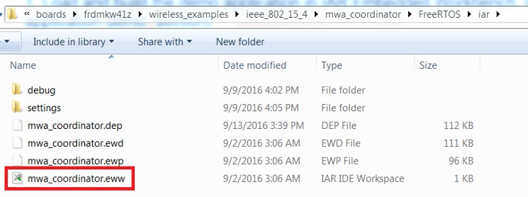
-
After the workspace is open, select the project
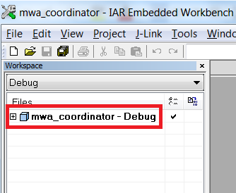
-
Click the Make button to build the project
Download the coordinator application demo
- Connect your FRDM-KW41Z board to your PC
-
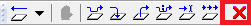
Click on the Download and Debug button (green arrow located on the toolbar)
-
Once the project has loaded, the debugger should stop at main(). At this
point, we need to program an end device. So, terminate this debug session by
clicking the terminate button shown in the figure below
- Unplug this board and connect a second FRDM-KW41Z board
Load and build the end device application demo
-
Navigate to the mwa_end_device IAR workspace (located at
<install_dir>\boards\frdmkw41z\wireless_examples\ieee802_15_4\mwa_end_device\FreeRTOS\iar)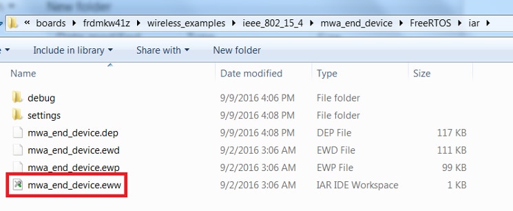
-
After the workspace is open, select the project
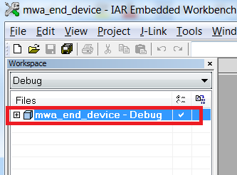
-
Click the Make button to build the project
Download the coordinator application demo
- Connect your second FRDM-KW41Z board to your PC (if not done so already)
-
Click on the Download and Debug button (green arrow located on the toolbar)
-
Once the project has loaded, the debugger should stop at main(). At this
point, we need to run the coordinator and end device together. So, terminate
this debug session by clicking the terminate button shown in the figure
below
- Unplug this board and connect both boards to your host PC
Run the coordinator application demo
-
Open a Terminal Emulator program and open a session to one of the FRDM-KW41Z
COM ports
- 115,200 baud rate
- No parity
- 8 data bits
- 1 stop bit
-
Open a second Terminal Emulator program and open a session to the other
FRDM-KW41Z COM port. Configure the terminal with these settings:
- 115,200 baud rate
- No parity
- 8 data bits
- 1 stop bit
- Press the reset button on both boards
-
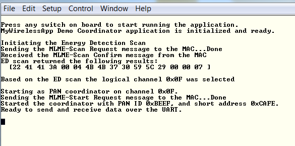
The coordinator device should display the following screen:
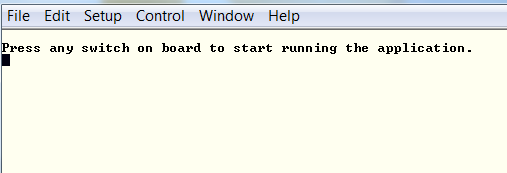
-
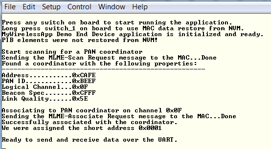
The end device should display the following screen:
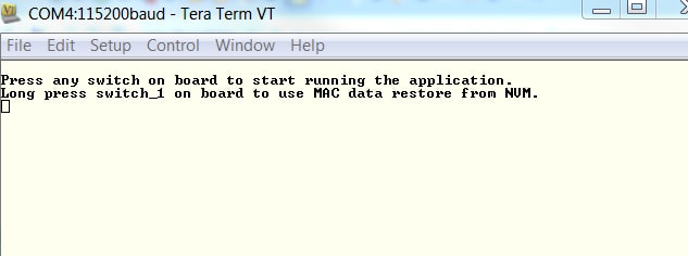
-
Press any switch on the coordinator board first. The screen should then
display the following:

-
Then, press any switch on the end device board. The end device should then
connect and display the following screen

- You should now be able to type characters into either terminal and see the characters echoed in the opposite terminal
-
Refer to
<connectivitysoftware_install_folder>\docs\wireless\IEEE 802.15.4\
                                                IEEE 802.15.4 MAC Demo Applications User's Guide.pdf
document for instructions on how to run all the demo applications
IEEE 802.15.4 - Running a demo using MCUXpresso IDE
Import the MCUXpresso SDK
- Open up the MCUXpresso IDE
-
Switch to the Installed SDKs view within the MCUXpresso IDE window
- Open Windows Explorer, and drag and drop the FRDM-KW41Z SDK (unzipped) file into the "Installed SDKs" view
-
You will get the following pop-up. Click OK to continue
the import:
-
The installed SDK will appear in the Installed SDKs view as shown below:
Build an Example Application
The following steps will guide you through opening the IEEE 802.15.4 example.
-
Find the Quickstart Panel in the lower left-hand corner
-
Then, click on Import SDK examples(s)
-
Click on the frdmkw41z board to select that you want to import an example
that can run on that board, and then click Next
-
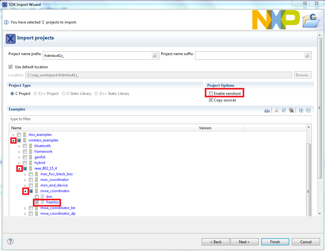
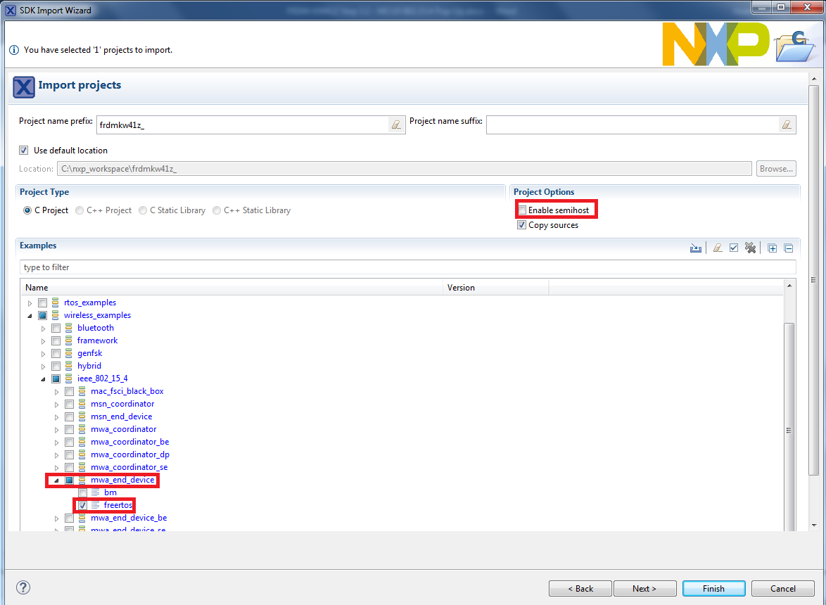
Use the arrow button to expand the "wireless_examples"
category, and then under the 'ieee_802_15_4' category expand
the 'mwa_coordinator' project and select the
'freertos' version of the project. To use the UART for printing
(instead of the default semihosting), clear the "Enable
semihost" checkbox under the project options. Then, click Next
-
On the Advanced Settings wizard, clear the checkbox "Redirect
SDK "PRINTF" to C library
"printf"" in order to use the MCUXpresso SDK
console functions for printing instead of generic C library ones. Then, click Finish
-
Now, build the project by clicking on the project name and then in the
Quickstart Panel click on Build
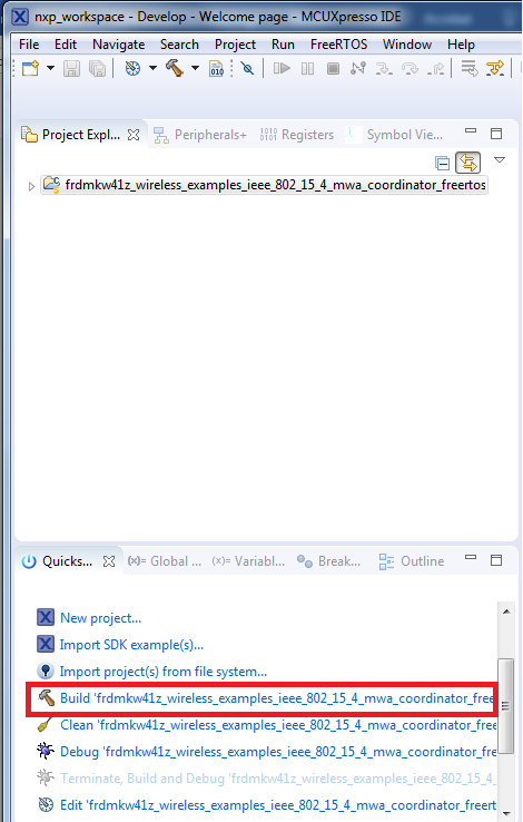
-
You can see the status of the build in the Console tab
Download the coordinator device application demo
- Now that the project has been compiled, you can now flash it to the board and run it
-
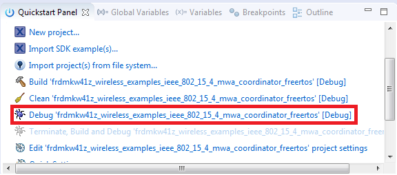
Make sure that the FRDM-KW41Z board is plugged in, and click in the
Quickstart Panel click on "Debug
"frdmkw41z_wireless_examples_ieee_802_15_4_maw_coordinator_freertos"
[Debug]"
-
MCUXpresso IDE will probe for connected boards and should find the JLink
debug probe that is part of the integrated OpenSDA circuit on the
FRDM-KW41Z. Click OK to continue
-
You may see the following message if this is your first debug with JLink of
the day. Click on the checkbox at the bottom not to display the message
again, and then click on Accept
-
The firmware will be downloaded to the board and the debugger started
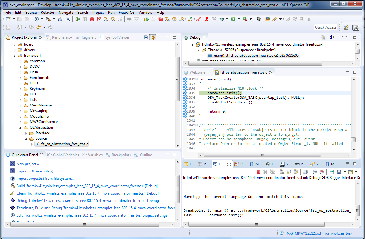
-
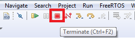
At this point, we need to program an end device. So, terminate this debug
session by clicking the Terminate button shown in the figure below. Then
unplug this board, and plug up your second board
Download the end device application demo
- Connect your second FRDM-KW41Z board to your PC (if not already done)
-
Import the wireless_demos → ieee_802_15_4 → mwa_end_device_freertos demo
using the same steps as you did for the coordinator demo
- Build and load the end device demo using the same steps as before so that the 2nd FRDM-KW41Z has this firmware on it
-
Stop the debugger
Run the coordinator application demo
-
Open a Terminal Emulator program and open a session to one of the FRDM-KW41Z
COM ports. Configure the terminal with these settings:
- 115,200 baud rate
- No parity
- 8 data bits
- 1 stop bit
-
Open a second Terminal Emulator program and open a session to the other
FRDM-KW41Z COM port. Configure the terminal with these settings:
- 115,200 baud rate
- No parity
- 8 data bits
- 1 stop bit
- Press the reset button on both boards
-
The coordinator device should display the following screen:

-
The end device should display the following screen:

-
Press any switch on the coordinator board first. The screen should then
display the following:
-
Then, press any switch on the end device board. The end device should then
connect and display the following screen
- You should now be able to type characters into either terminal and see the characters echoed in the opposite terminal
-
Refer to
<mcuxpresso sdk directory>\docs\wireless\IEEE 802.15.4\IEEE
                      802.15.4 MAC Demo Applications User's Guide.pdf
document for instructions on how to run all the demo applications
Gen FSK
GFSK - IAR Embedded Workbench IDE
These steps show how to:
- Load and build the demo application in IAR Embedded Workbench
- Download and run the demo application
The example used below is for the Generic FSK Connectivity Test demo, but these steps can be applied to any of the Wireless Connectivity demo applications.
Load and build the application demo
-
Navigate to the Connectivity Test IAR workspace (located at
<install_dir>\boards\frdmkw41z\wireless_examples\genfsk\connectivity_test_genfsk\FreeRTOS\iar)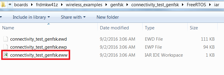
-
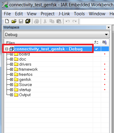
After the workspace is open, select the project
-
Click the Make button to build the project
Download and Run the application demo
- Connect your FRDM-KW41Z board to your PC
-
Click on the Download and Debug button (green arrow located on the
toolbar)
-
Once the project has loaded, the debugger should stop at main(). Open
a Terminal Emulator program and open a session to your FRDM-KW41Z
COM port. Configure the terminal with these settings:
- 115,200 baud rate
- No parity
- 8 data bits
- 1 stop bit
-
Click the Go button to resume operation
-
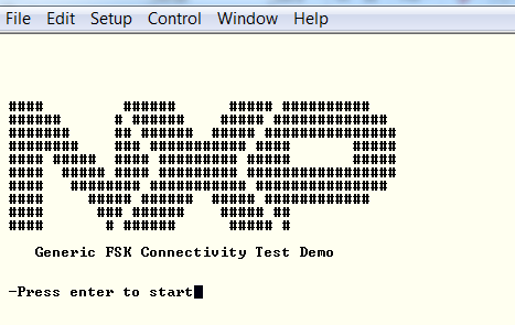
The following output will be displayed in the serial terminal. If you don't see this output, verify your terminal settings and
connections

-
Refer to
<connectivitysoftware_install_folder>
                      \docs\wireless\GENFSK\Generic FSK Link Layer Quick Start
                      Guide.pdf
document for more information on this demo application
GFSK - Running a demo using MCUXpresso IDE
Import the MCUXpresso SDK
- Open up the MCUXpresso IDE
-
Switch to the Installed SDKs view within the MCUXpresso IDE window
- Open Windows Explorer, and drag and drop the FRDM-KW41Z SDK (unzipped) file into the "Installed SDKs" view
-
You will get the following pop-up. Click OK to
continue the import:
-
The installed SDK will appear in the Installed SDKs view as shown
below:
Build an Example Application
The following steps will guide you through opening the GenFSK example.
-
Find the Quickstart Panel in the lower left-hand corner
-
Then, click on Import SDK examples(s)
-
Click on the frdmkw41z board to select that you want to import an
example that can run on that board, and then click Next
-
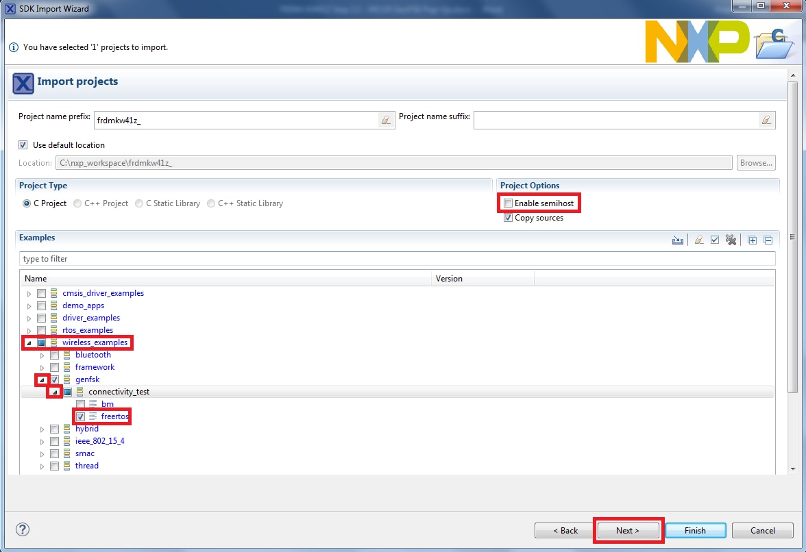
Use the arrow button to expand the "wireless_examples"
category, and then under the 'genfsk' category expand
the 'connectivity_test' project and select the
'freertos' version of the project. To use the UART for
printing (instead of the default semihosting), clear the
"Enable semihost" checkbox under the
project options. Then, click Next
-
On the Advanced Settings wizard, clear the checkbox
"Redirect SDK "PRINTF" to C library
"printf"" in order to use the
MCUXpresso SDK console functions for printing instead of generic C
library ones. Then click Finish
-
Now, build the project by clicking on the project name and then in the
Quickstart Panel click on Build
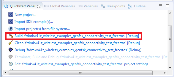
-
You can see the status of the build in the Console tab
Run an Example Application
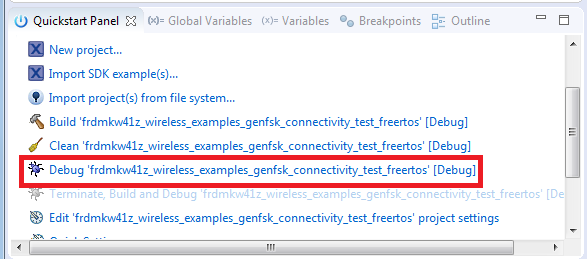
- Now that the project has been compiled, you can now flash it to the board and run it
-
Make sure that the FRDM-KW41Z board is plugged in, and click in the
Quickstart Panel click on "Debug
"frdmkw41z_wireless_examples_genfsk_connectivity_test_freertos"
[Debug]"
-
MCUXpresso IDE will probe for connected boards and should find the
JLink debug probe that is part of the integrated OpenSDA circuit on
the FRDM-KW41Z. Click OK to continue
-
You may see the following message if this is your first debug with
JLink of the day. Click on the checkbox at the bottom not to display
the message again, and then click on Accept
-
The firmware will be downloaded to the board and the debugger started
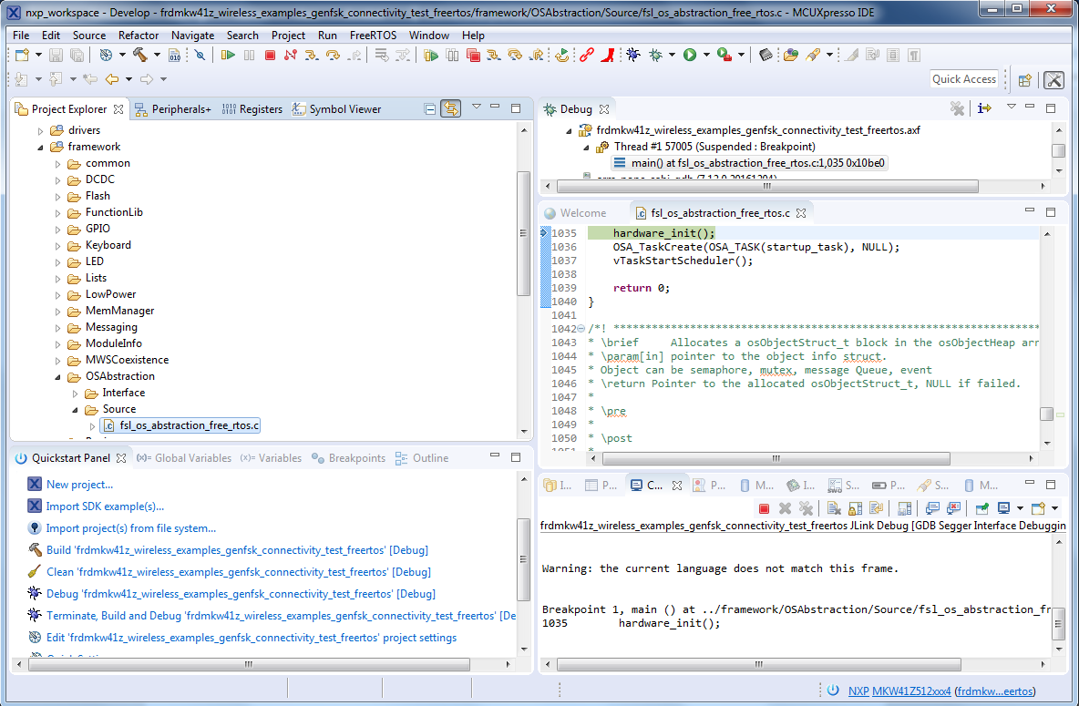
-
Hit the Terminate icon to stop the debugger
- Now, disconnect the board, and connect the second FRDM-KW41Z board. Follow the same debugger steps to flash the connectivity software to that board so that both boards have the same firmware on them
-
Now, with both boards connected, open a Terminal Emulator program and
open a session to your FRDM-KW41Z COM port for each board. Configure the terminal with these settings:
- 115,200 baud rate
- No parity
- 8 data bits
- 1 stop bit
- Hit the reset button on both boards
-
The following output will be displayed in each of the two serial
terminals
-
Refer to
<mcuxpresso sdk directory>\docs\wireless\GENFSK\Generic FSK
                      Link Layer Quick Start Guide.pdf
document for more information on this demo application
Hybrid (Bluetooth Low Energy + Thread)
Bluetooth Low Energy + Thread - IAR Embedded Workbench IDE
The following steps will guide you through creating a simple Thread network. A hybrid Bluetooth Low Energy + Thread project will be loaded onto the 1st board, so that the board can be controlled via a Bluetooth smartphone application. While a Thread-only project will be loaded onto the 2nd board and controlled via a serial terminal.
Build a Hybrid Bluetooth Low Energy + Thread Application
-
Navigate to the Hybrid Bluetooth Low Energy Thread Router workspace
(located at
<install_dir>\boards\frdmkw41z\wireless_examples\hybrid\ble_thread_router_wireless_uart\freertos\iar)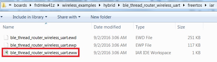
-
After the workspace is open, select the project
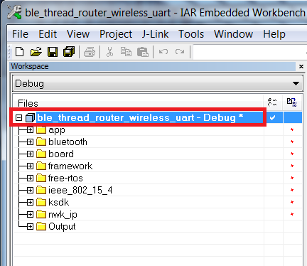
-
Click the Make button to build the project
Download and Run the application demo
- Connect the first FRDM-KW41Z board to your PC
-
Click on the Download and Debug button (green arrow located on the
toolbar)
-
You may see the following message if this is your first debug with
JLink of the day. Click on the checkbox at the bottom not to display
the message again, and then click on Accept

- The firmware will be downloaded to the board and the debugger started
-
Right now we only want to load the firmware to the first board, so
hit the Terminate icon to stop the debugger

Download the Thread router application demo to the 2nd board
The Hybrid board needs a Thread node to communicate with, so Thread firmware needs to be loaded onto the second board. The Router Eligible End Device project will be loaded onto board #2.
- Unplug the first FRDM-KW41Z board and plug-in the second FRDM-KW41Z board to your PC
-
Navigate to the Router Eligible End Device project workspace (located
at
<install_dir>\boards\frdmkw41z\wireless_examples\thread\router_eligible_device\freertos\iar)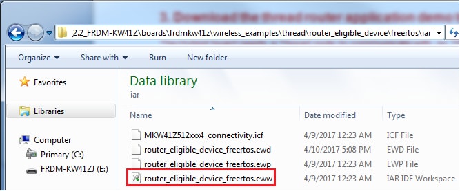
- Build and flash the Router Eligible End Device demo using the same steps as before so that the 2nd FRDM-KW41Z has the thread_router firmware loaded onto it
-
Stop the debugger
Run the hybrid demo
-
Open a Terminal Emulator program and open a session to your
FRDM-KW41Z COM port that has the thread_router_eligible project
firmware on it (board #2). Configure the terminal with these settings:
- 115,200 baud rate
- No parity
- 8 data bits
- 1 stop bit
-
Hit the Reset button on board #2, which can be found near where the
USB cable is plugged in. You should see the following on the
terminal:

- Plug-in board #1 that has the Hybrid Bluetooth Low Energy + Thread firmware loaded on it, so that both boards are now connected
-
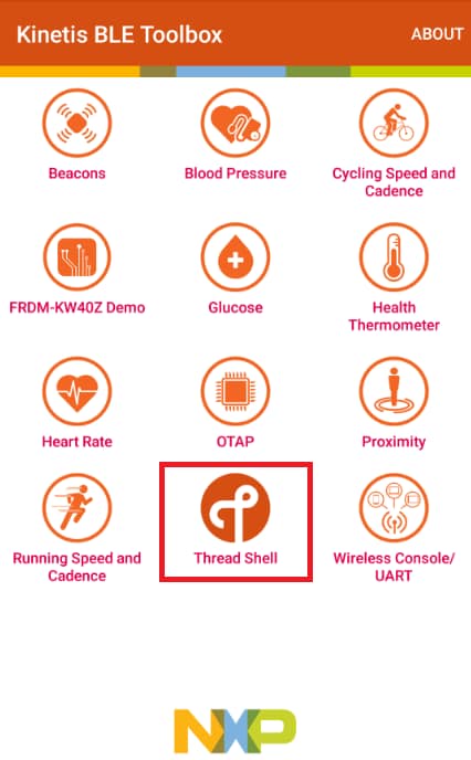
Open the Kinetis Bluetooth Low Energy Toolbox application on your
mobile device and click on the Thread Shell function

-
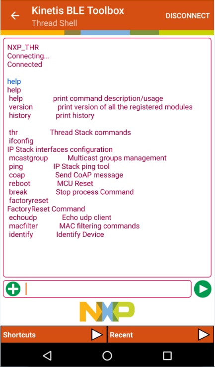
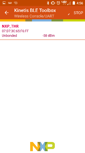
The Kinetis Bluetooth Low Energy Toolbox application should start
scanning and find the FRDM-KW41Z board (NXP_THR). Select the NXP_THR
device

-
The Kinetis Bluetooth Low Energy Toolbox should now be connected to
the device. Using the keyboard on your mobile app that appears, you
can type commands to the FRDM-KW41Z device. Type 'help'
to see the list of possible commands. Outputs from the FRDM-KW41Z
board should appear in the app as well
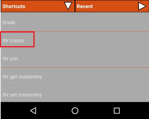
-
Start a new Thread network by typing 'thr create' or by
selecting that command in the Shortcuts menu

- Inside the Tera Term connection to the second board (that is just running Thread), join this new network by typing 'thr join'
- Take note of the ML64 address listed in the terminal for R2 by typing 'ifconfig'
-
Inside the smartphone app terminal, type in the command to toggle the LED
coap CON POST <ip_address>/led toggle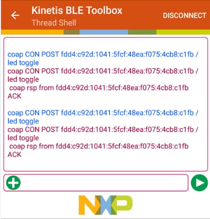
-
Refer to
<mcuxpresso sdk directory>\docs\wireless\Thread\Kinetis
                    Thread Stack Demo Applications User's Guide.pdf
document for more information on this demo application
Bluetooth Low Energy + Thread - Running a demo using MCUXpresso IDE
The following steps will guide you through creating a simple Thread network. A hybrid Bluetooth Low Energy + Thread project will be loaded onto the 1st board, so that the board can be controlled via a Bluetooth smartphone application. While a Thread-only project will be loaded onto the 2nd board and controlled via a serial terminal.
Import the MCUXpresso SDK
- Open up the MCUXpresso IDE
-
Switch to the Installed SDKs view within the MCUXpresso IDE window
- Open Windows Explorer, and drag and drop the FRDM-KW41Z SDK (unzipped) file into the "Installed SDKs" view
-
You will get the following pop-up. Click OK to
continue the import:
-
The installed SDK will appear in the Installed SDKs view as shown
below:
Build a Hybrid Bluetooth Low Energy + Thread Application
The following steps will guide you through opening the hybrid example. This project will be loaded to one board, while another project will be loaded on the 2nd board.
-
Find the Quickstart Panel in the lower left-hand corner
-
Then, click on Import SDK examples(s)
-
Click on the frdmkw41z board to select that you want to import an
example that can run on that board, and then click Next
-
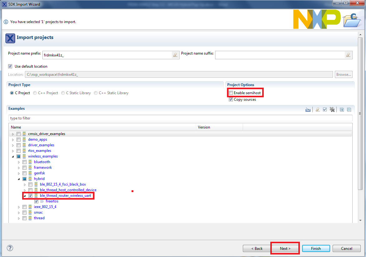
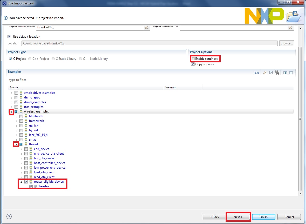
Use the arrow button to expand the "wireless_examples"
category, and then under the 'hybrid' category expand
the 'ble_thread_router_wireless_uart' project and
select the 'freertos' version of the project. To use the
UART for printing (instead of the default semihosting), clear the
"Enable semihost" checkbox under the
project options. Then, click Next
-
On the Advanced Settings wizard, clear the checkbox
"Redirect SDK "PRINTF" to C library
"printf"" in order to use the
MCUXpresso SDK console functions for printing instead of generic C
library ones. Then click Finish
-
Now, build the project by clicking on the project name and then in the
Quickstart Panel click on Build
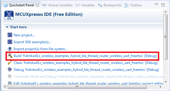
-
You can see the status of the build in the Console tab
Download the hybrid application demo to the 1st board
- Now that the project has been compiled, you can now flash it to the board and run it
-
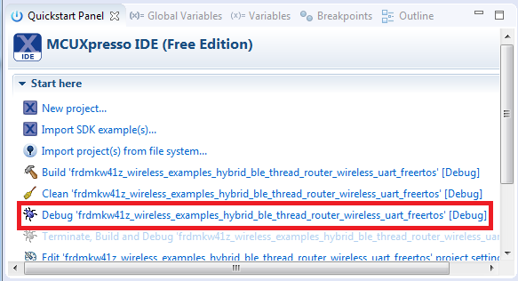
Make sure that the FRDM-KW41Z board is plugged in, and click in the
Quickstart Panel click on "Debug
"frdmkw41z_wireless_examples_hybrid_ble_thread_router_wireless_uart_freertos"
[Debug]"
-
MCUXpresso IDE will probe for connected boards and should find the
JLink debug probe that is part of the integrated OpenSDA circuit on
the FRDM-KW41Z. Click OK to continue
-
You may see the following message if this is your first debug with
JLink of the day. Click on the checkbox at the bottom not to display
the message again, and then click on Accept
-
The firmware will be downloaded to the board and the debugger started
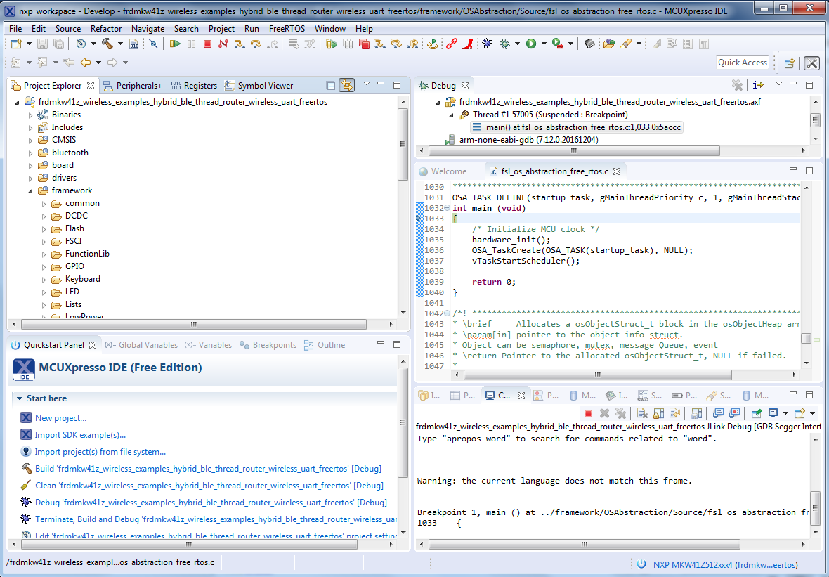
-
Right now, we only want to load the firmware to the first board, so
hit the Terminate icon to stop the debugger
Download the Thread router application demo to the 2nd board
The Hybrid board needs a Thread node to communicate with, so Thread firmware needs to be loaded onto the second board. The Router Eligible End Device project will be loaded onto board #2.
- Unplug the first FRDM-KW41Z board and plug-in the second FRDM-KW41Z board to your PC
-
Import the
wireless_demos → thread → router_eligible_device → freertos
demo using the same steps as you did for the hybrid demo
- Build and load the end device demo using the same steps as before so that the 2nd FRDM-KW41Z has the thread_router firmware on it
-
Stop the debugger
Run the hybrid demo
-
Open a Terminal Emulator program and open a session to your
FRDM-KW41Z COM port that has the thread_router_eligible project
firmware on it (board #2). Configure the terminal with these settings:
- 115,200 baud rate
- No parity
- 8 data bits
- 1 stop bit
-
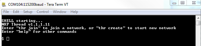
Hit the Reset button on board #2, which can be found near where the
USB cable is plugged in. You should see the following on the
terminal:
- Plug-in board #1 that has the Hybrid Bluetooth Low Energy + Thread firmware loaded on it, so that both boards are now connected
-
Open the Kinetis Bluetooth Low Energy Toolbox application on your
mobile device and click on the Thread Shell function
-
The Kinetis Bluetooth Low Energy Toolbox application should start
scanning and find the FRDM-KW41Z board (NXP_THR). Select the NXP_THR
device
-
The Kinetis Bluetooth Low Energy Toolbox should now be connected to
the device. Using the keyboard on your mobile app that appears, you
may type commands to the FRDM-KW41Z device. Type 'help'
to see the list of possible commands. Outputs from the FRDM-KW41Z
board should appear in the app as well

-
Start a new Thread network by typing 'thr
create' or by selecting that command in the
"Shortcuts" menu
- Inside the Tera Term connection to the second board (that is just running Thread), join this new network by typing 'thr join'
- Take note of the ML64 address listed in the terminal for R2 by typing 'ifconfig'
-
Inside the smartphone app terminal, type in the command to toggle the LED
coap CON POST <ip_address>/led toggle
-
Refer to
<mcuxpresso sdk directory>\docs\wireless\Thread\Kinetis
                    Thread Stack Demo Applications User's Guide.pdf
document for more information on this demo application
4. Create
4.1 Create an Application for the FRDM-KW41Z
4.2 Clone an Example Project from MCUXpresso SDK
Option A: Use the MCUXpresso IDE to clone an example project.
Use MCUXpresso IDE
- Open the MCUXpresso IDE
-
Click Import SDK Examples from the QuickStart Panel
-
Select the FRDM-KW41Z board in the Import Wizard. Then, select Next
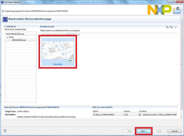
-
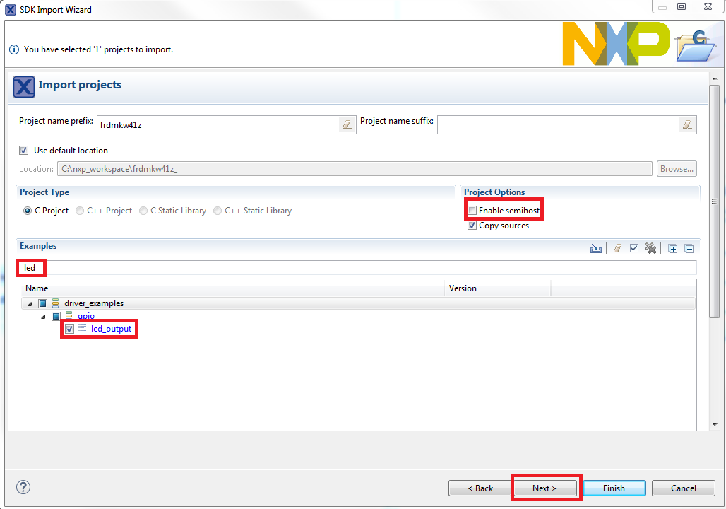
Type "LED" into the search bar, and select the "led_output" project
under the GPIO driver example. Then, select Next. This will create a
new standalone copy of this LED project and put it into the
MCUXpresso workspace. To use the UART for printing (instead of the
default semihosting), clear the "Enable semihost" checkbox under the
project options. Then, click Next
-
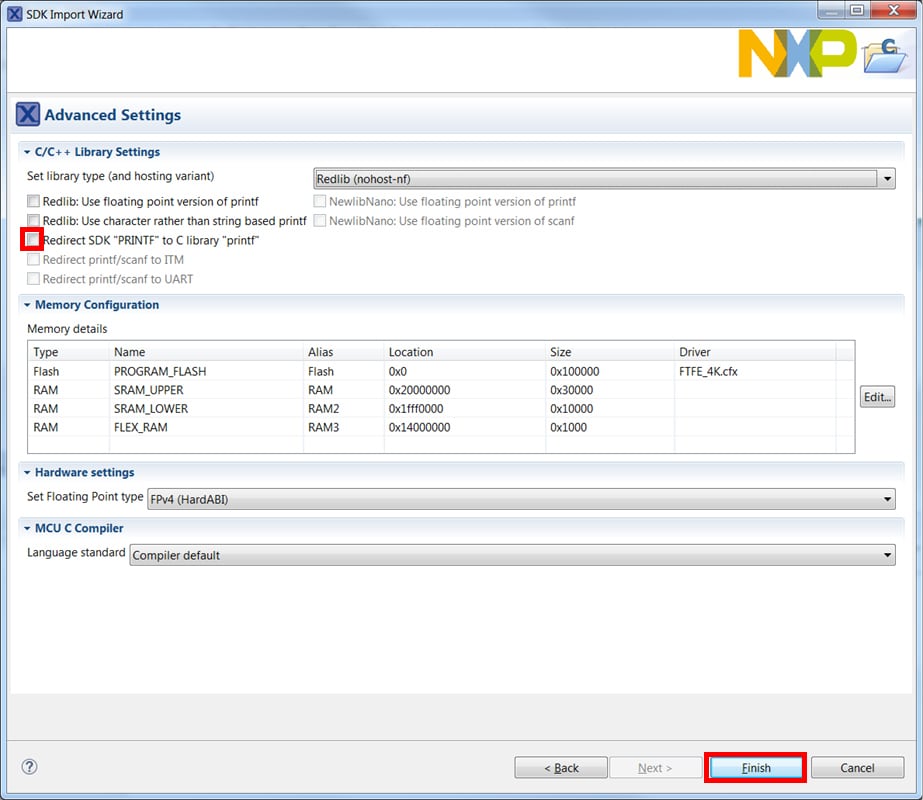
On the Advanced Settings wizard, clear the checkbox "Redirect SDK"
"PRINTF" to C library "printf"" in order to use the MCUXpresso SDK
console functions for printing instead of generic C library ones.
Then click Finish
-
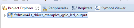
Click on the "led_output" project in the Project Explorer View and
build, compile, and run the demo as described previously
- You should see a red LED blinking on the board
- Terminate the debug session
Option B: Use the MCUXpresso Config Tools to clone an existing MCUXpresso SDK example for use with third-party IDEs.
Use MCUxpresso Config Tools
- Open the MCUXpresso Config Tools
-
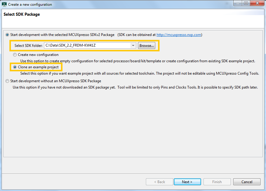
In the wizard that comes up, browse to the place where the
MCUXpresso SDK was unzipped, and then select the "Clone an example
project" radio button and click Next
-
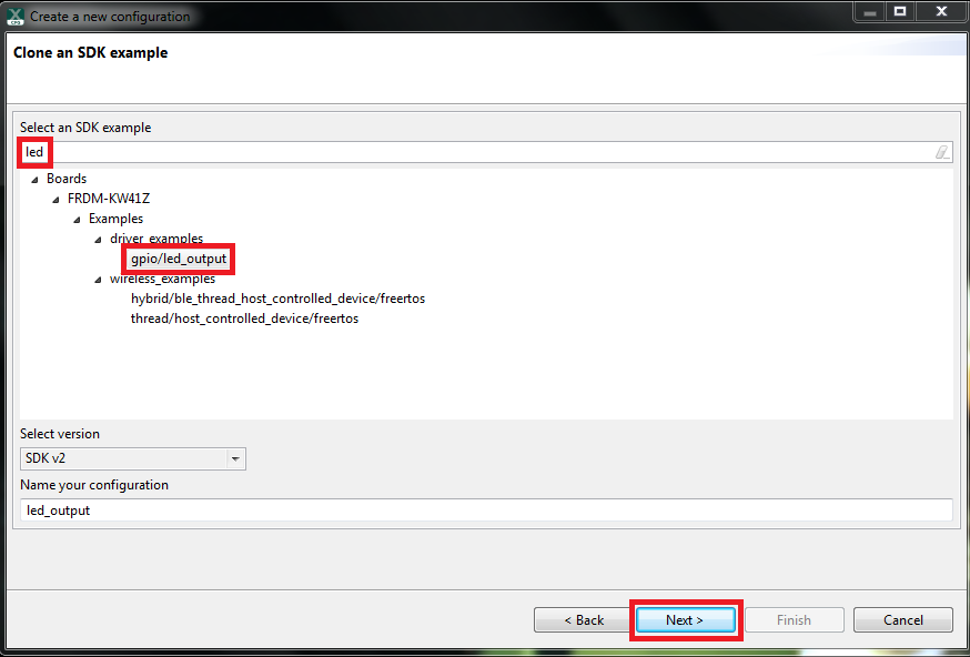
Select the project to clone. For this example, we want to use the
LED project. You can filter for this by typing "LED" in the filter
box and then selecting the "gpio/led_output" project. Then click
Next
-
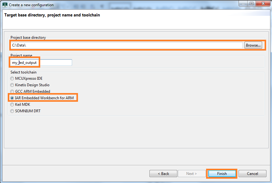
Then, select the directory you want to place the cloned project, give
it a name and select the IDE to use. Note that only IDEs that were
selected in the online SDK builder when the SDK was built will be
available. Then click Finish
- After cloning go to the directory you selected and open up the project for your IDE. Import, compile, and run the project as done in previous sections
- You should see a red LED blinking on the board
- Terminate the debug session
4.3 Use the Pins Tool
Now, let's use the Pins Tool that is part of the MCUXpresso Config Tools to show how to add a new GPIO pin to your project to blink an LED.
Use Pins Tool
-
Open MCUXpresso Config Tools
-
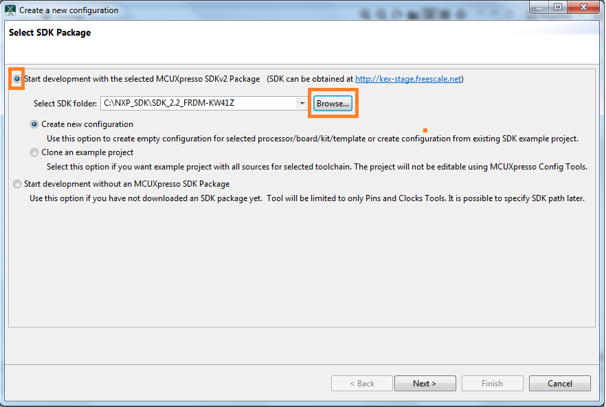
The wizard will ask if you want to start development with or without
an SDK. Choose to start development with the SDK and that we want to
create a new configuration. Use the "Browse" button to navigate to
the location of your unzipped SDK installation
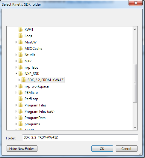
-
Select the SDK top-level folder from your file system. Select OK
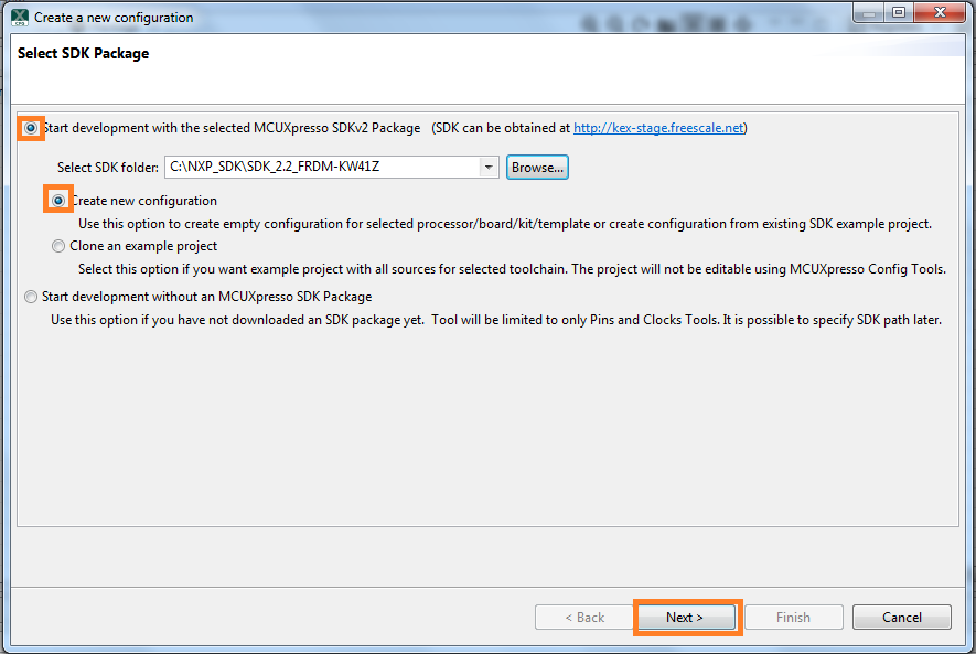
-
The wizard asks to create a new configuration or clone an example
project. We will Create a new configuration that will be based on
the "led_output" project settings from the SDK. Select Next to
continue
-
Search for the led_output example by typing "LED" in the search bar.
Select the led_output example and press Finish

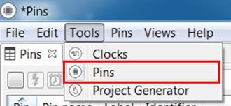
-
Open the Pins Tool by selecting Tools → Pins from the toolbar
-
The Pins Tool should now display the pin configuration for the
led_output project
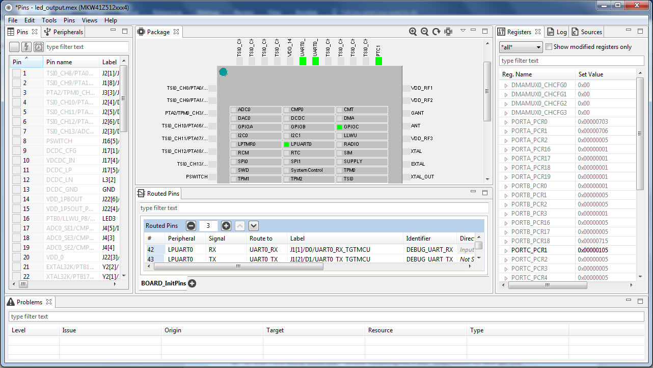
-
In the Pins view, click the "Show Routed/All Pins" checkbox to see
all the routed pins. Routed pins have a check in a green box next to
the pin name. The functions selected for each routed pin are
highlighted in green in the table
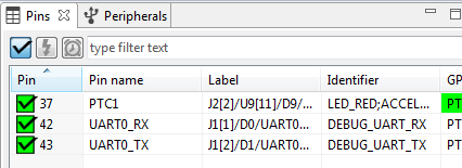
-
In the current configuration,
PTC1is routed as a GPIO to toggle the red LED. Let's disablePTC1, and change the MUX setting ofPTA18to use its GPIO functionality to drive the blue LED -
Disable
PTC1(red LED) as a GPIO by clicking thePTC1field under the GPIO column. The pin will then be disabled (pin will no longer have check in box) and thus disappear from the list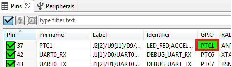
-
Now, route
PTA18as a GPIO. First, deselect the "Show Routed All/Pins" so that all the pins are displayed again. Then, searchPTA18in the Pins view. Finally, click the box under the GPIO column. The box will highlight in green, and a check will appear next to the pin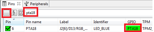
-
The updated view will appear as below once you clear the filtered
text. Note that
PTB21also appears in the Routed Pins tab andPTB22has been removed. The pin_mux.c file has been updated to reflect the change as well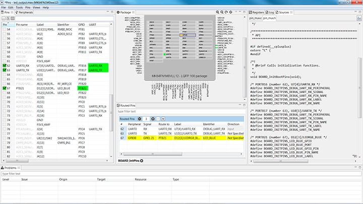
-
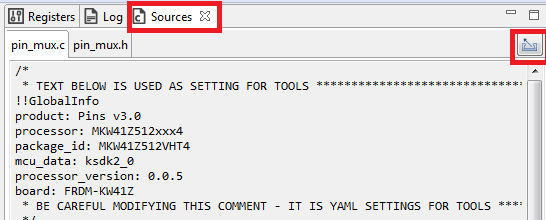
Now, export the pin_mux.c and pin_mux.h files by clicking on the Sources tab on the right side to get to the Sources view, and selecting the export icon
-
Select the directory to export the pin_mux.c and pin_mux.h files.
In this example export to the "board" folder in the led_output
project in the workspace that was created in the previous section
(i.e.
C:\nxp_workspace\frdmkw41z_driver_examples_gpio_led_output\board). Select Finish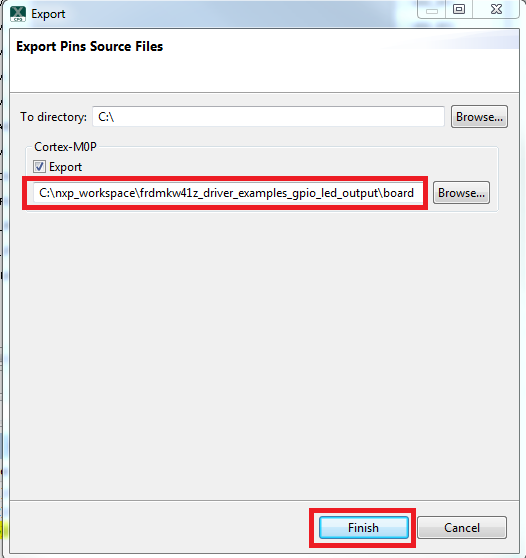
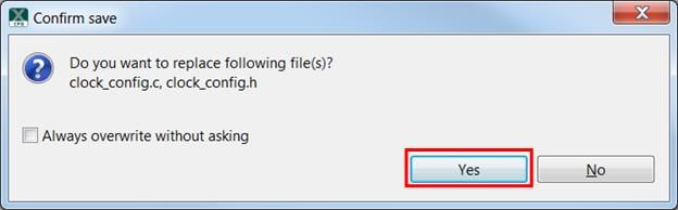
-
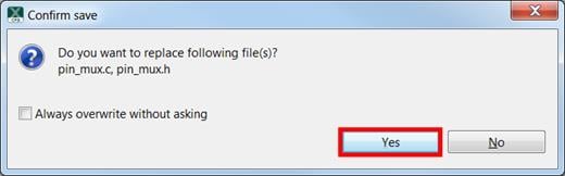
Click Yes to replace the existing pin_mux.c and pin_mux.h files
-
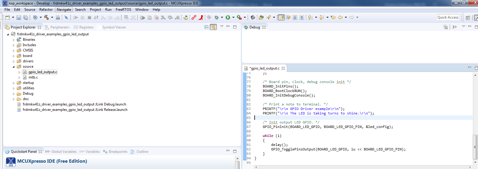
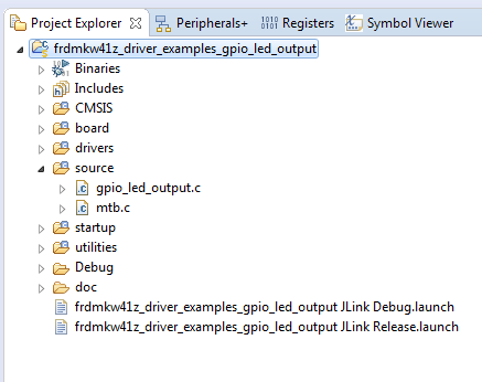
We'll use MCUXpresso IDE for the rest of the instructions but the
same steps can be done in other 3rd party IDEs. Under the
"led_output" project, double-click the gpio_led_output.c file in the
source folder to display the file in the editor. Notice that the
macros used in the GPIO driver functions refer to the BOARD_LED
(i.e. red LED)
-
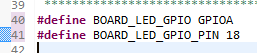
Change the defines for BOARD_LED_GPIO to the "GPIOA" and the
BOARD_LED_GPIO_PIN to "18"
- Build and download the project as done in the previous section
- Run the application. You should now see the blue LED blinking!
- Terminate the debug session
4.4 Use the Clocks Tool
Next, use the Clocks Tool that is part of the MCUXpresso Config Tools to change the clock settings and change the rate that the LED blinks.
Use the Clocks Tool
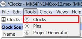
- Open MCUXpresso Config Tools
- Open the Clocks Tool from the toolbar: Tools → Clocks
- The clock configuration for the 'led_output' project
will appear in the Clocks Tool:
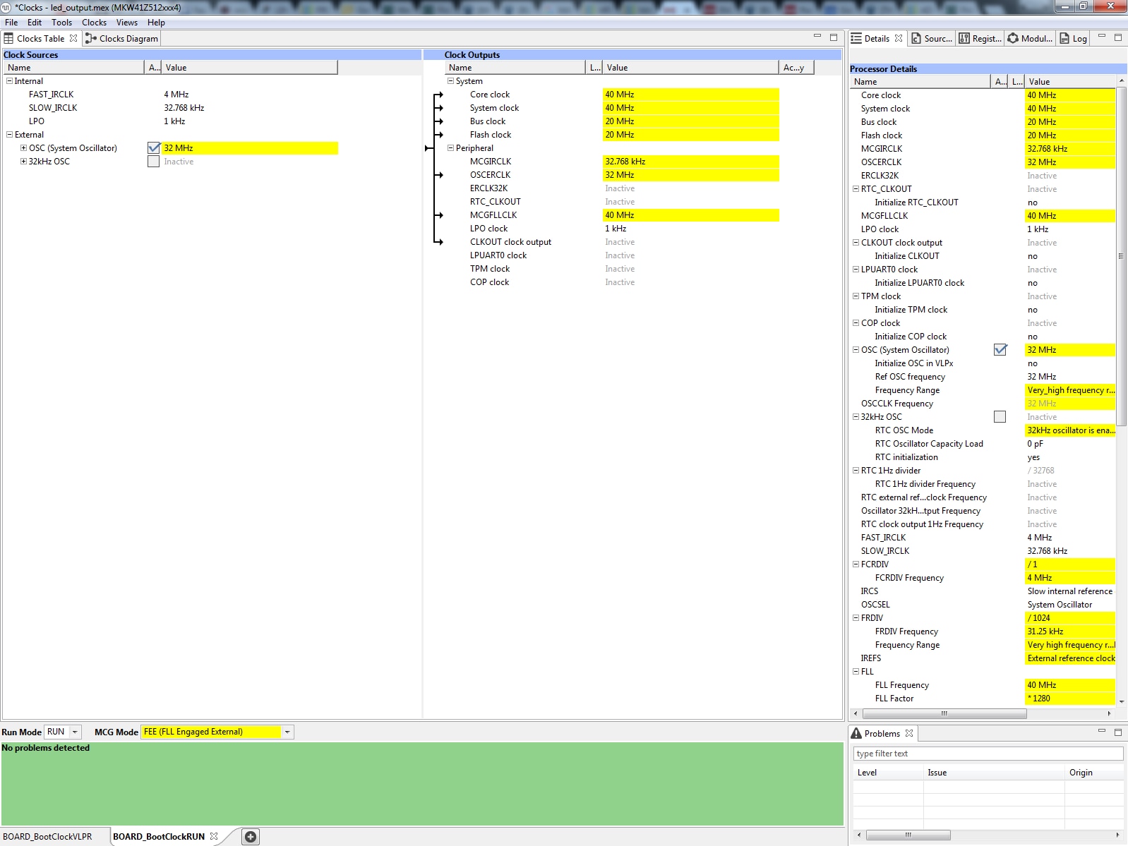
- Switch to the Clocks Diagram view by clicking the tab in the upper
left corner, and ensure that the BOARD_BootClockRUN clock mode is
being displayed by clicking the tab in the lower left corner
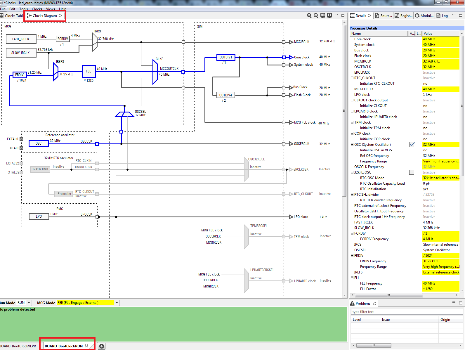
- Change the core clock frequency by clicking in the Core Clock field
and typing "10 MHz". You'll see all the associated
clock frequencies automatically change as well then
- Now, open the "Sources" tab and export the clock_config.c
and clock_config.h files

-
Select the directory to export the pin_mux.c and pin_mux.h files.
In this example export to the “board” folder in the
led_output project in the workspace that was created in the
previous section (i.e.
C:\nxp_workspace\frdmkw41z_driver_examples_gpio_led_output\board). Select Finish
- Press Yes to replace the existing clock_config.c and clock_config.h
files
- Now, open the LED project in your IDE, build, download, and run
the project as you did before
- The blue LED should now be blinking at a much slower rate
4.5 Success
With the application modified, you will see the FRDM-KW41Z's blue LED slowly blinking. You can also view terminal output using the terminal program.
Tera Term Tutorial
Tera Term Tutorial
Tera Term is a very popular open source terminal emulation application. This program can be used to display information sent from your NXP development platform's virtual serial port.
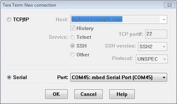
- Download Tera Term from SourceForge. After the download, run the installer and then return to this webpage to continue
- Launch Tera Term. The first time it launches, it will show you the following dialog. Select the Serial option. Assuming your board is plugged in, there should be a COM port automatically populated in the list
- Configure the serial port settings (using the COM port number identified earlier) to 115,200 baud rate, 8 data bits, no parity, and 1 stop bit. To do this, go to Setup → Serial Port and change the settings
- Verify that the connection is open. If connected, Tera Term will show something like below in its title bar
- You're ready to go
PuTTY Tutorial
PuTTY Tutorial
PuTTY is a popular terminal emulation application. This program can be used to display information sent from your NXP development platform's virtual serial port.
- Download PuTTY using the button below. After the download, run the installer and then return to this webpage to continue
- Launch PuTTY by either double-clicking on the *.exe file you downloaded or from the Start menu, depending on the type of download you selected
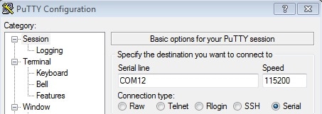
- Configure In the window that launches, select the Serial radio button and enter the COM port number that you determined earlier. Also enter the baud rate, in this case 115,200
- Click Open to open the serial connection. Assuming the board is connected and you entered the correct COM port, the terminal window will open. If the configuration is not correct, PuTTY will alert you
- You're ready to go
Connectivity Test Application
Connectivity Test Application
The Connectivity Test Application is a SMAC-based Demo Application, which provides the user with means to test basic transmission-reception functionalities along with several advanced testing features based on the ASP and SMAC APIs.
Configuration
The runtime configuration is performed using shortcut keys, which are available in most of the application's menus. The menus or tests will change their behavior based on what settings are applied.
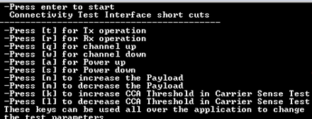
- 't' - brings up the configuration menu for the transmitter in both PER and Range tests
- 'r' - brings up the configuration menu for the receiver in both PER and Range tests
- 'q' - increments channel number [11-26]
- 'w' - decrements channel number [11-26]
- 'a' - increments output power value
- 's' - decrements output power value
- 'n' - increments the length of the payload (used in PER TX and Transmission Control)
- 'm': decrements the length of the payload (used in PER TX and Transmission Control)
- 'k' - increments the CCA threshold for the Carrier Sense test
- 'l' - decrements the CCA threshold for the Carrier Sense test
Application Usage
The Connectivity Test Application has four main features:
- Continuous Tests: Allows you to test the RF performance of the transceiver for basic transmitter and receiver functionality. The Test Mode application is a collection of modes consisting of the following tests
- Packet Error Rate: This menu depends on the 'r' or 't' shortcut key. Two boards are required to run this test, one of the boards shall be set in Rx and the other in Tx
- Range Test: This menu depends on the 'r' and 't' shortcuts. Two boards are required to run this test; the test is started and stopped only by user intervention and during its execution it will display the link quality for each received packet
-
Carrier Sense and Transmission Control: This menu allows the
user to choose between two tests:
- The Carrier Sense test performs ED continuously until the ED value is above the CCA threshold and then transmit a packet, which contains pseudo-random data with the payload size configured using 'n' and 'm' shortcuts
- The Transmission Control test displays a selection menu for number of packets identical with the one in PER TX test and then it prompts the user to enter the interpacket delay. After that, the application will start sending the selected number of packets with the selected interpacket delay, using pseudo-random data for the payload with the size configured with 'n' and 'm' shortcuts
For additional details on how to run the Connectivity Test Application, please refer to the "SMAC's Demonstration Applications User's Guide".
Design Resources
Board Information
Chip Documents
Software
Learn More
IoT Modular Gateway
The NXP modular IoT Gateway reference design enables large node networks (LNNs) with preintegrated, tested, and RF certified support for a wide array of wireless communications protocols including: Thread, ZigBee, and Wi-Fi. This range of capability allows developers to easily build gateways based on this solution, using their choice of wireless protocols for end-to-end wireless communications in LNN configurations with supporting cloud options such as Amazon Web Services (AWS).
Thread
Thread is an IPv6-based mesh networking protocol developed by industry leading technology companies, like NXP®, for connecting products around the home and in buildings to each other, to the internet and to the cloud. Thread networks are simple to install, highly secure, scalable to hundreds of devices and developed to run on low-power IEEE 802.15.4 chipsets. Find out more at: Thread Networking Protocol and Thread Group .
Sensors
Explore the world with a full assortment of NXP sensor solutions. From accelerometers, pressure sensors, touch sensors, and many more, NXP has a sensor solution for your project. Find out more at: Sensors.
NFC
Near Field Communication is a simple, intuitive technology that lets you interact securely with the world around you with a simple touch. Learn more about NXP’s NFC solutions at: NFC - Near Field Communication.
Support
Forums
Connect with other engineers and get expert advice on designing with Kinetis MCUs and Wireless Connectivity software. Go to Support or join the community discussion in one of our two dedicated communities:
On this page
- 1.1
Getting Started with the FRDM-KW41Z Development Board
- 1.2
Attach the USB Cable
- 1.3
Run the Out-of-Box Demo
- 2.1
Installing Software for the FRDM-KW41Z
- 2.2
Download MCUXpresso SDK with Connectivity Software
- 2.3
Install Your Toolchain
- 2.4
MCUXpresso Config Tools
- 2.5
Terminal Configuration
- 3.1
Build and Run Connectivity Demos on the FRDM-KW41Z
- 3.2
Explore the Connectivity Example Codes
- 3.3
Download the Bluetooth Low Energy Toolbox for your Smartphone
- 3.4
Build, Run, and Debug Wireless Connectivity Examples