Getting Started with FRDM-MCXA344
Contents of this document
-
Out of the Box
-
Get Software
-
Build and Run
-
Create
-
MCUXpresso Developer Experience
Sign in to save your progress. Don't have an account? Create one.
Purchase your FRDM-MCXA344
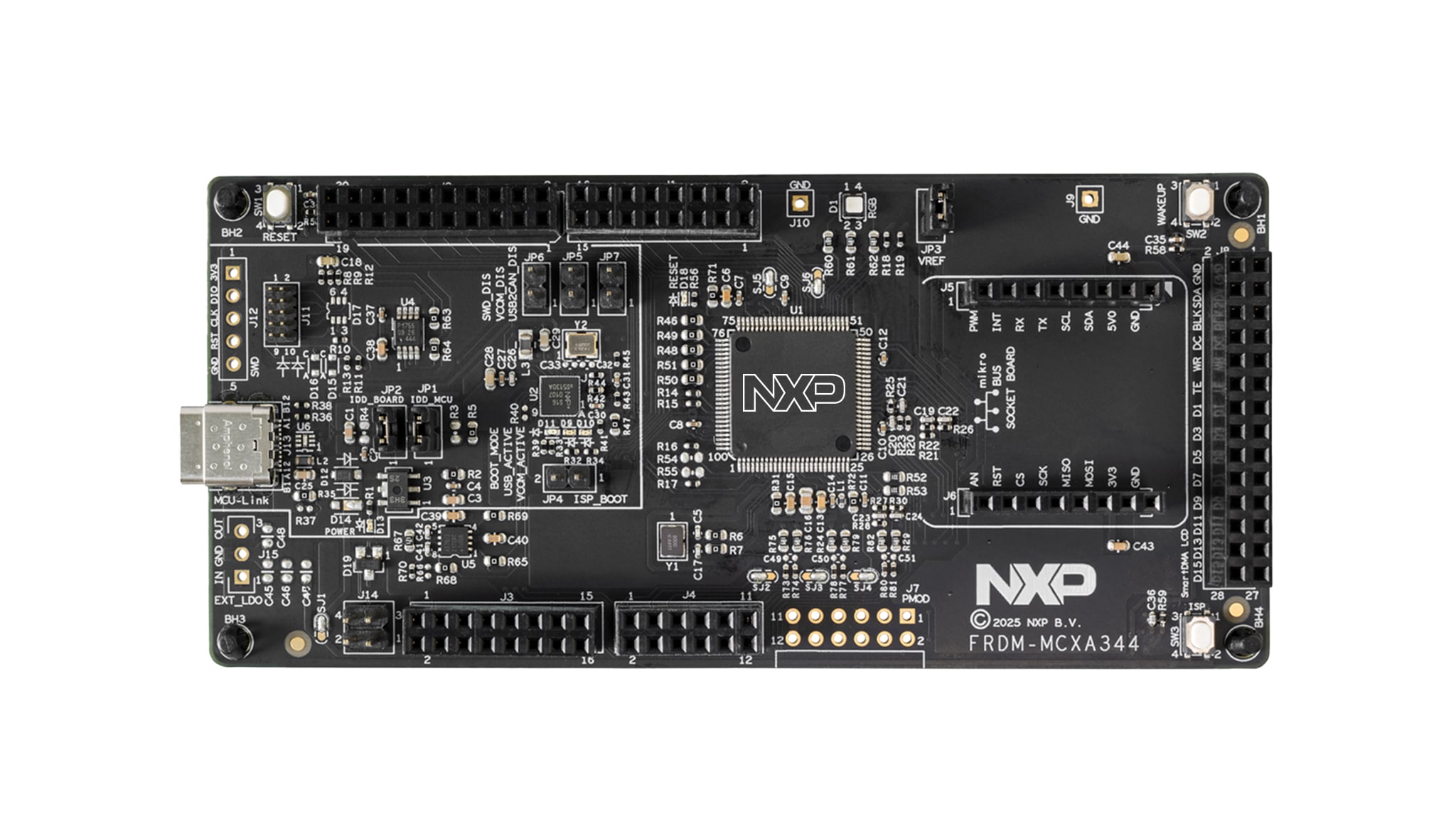
1. Out of the Box
Take your FRDM board for a test drive! You have the choice of either the sequence in a short video or following the detailed actions listed below.
1.1 Get Familiar with the Board
The FRDM-MCXA344 board comes pre-programmed with a LED blinky demo. This serves as a sanity check to verify that the device is functioning as expected out of the box.
1.2 Plug In the Board
Connect a USB Type-C cable from the connector J13 to a host computer or power supply to power up the board and run the demo program. At this point, you should see the RGB LED blinking in a steady rhythm.
2. Get Software
2.1 Install Your Toolchain
NXP offers a toolchain called MCUXpresso for Visual Studio (VS Code). Please download MCUXpresso for VS Code v25.06 or newer.

Learn how to install VS Code for your host PC with the following tutorial.
Want to use a different toolchain?
If you need help choosing, explore the MCUXpresso Suite of Software and Tools.
The MCUXpresso software development kit (SDK) includes support for other tools such as IAR , KEIL and command-line GCC .
2.2 Jump Start Your Design with the MCUXpresso SDK
The MCUXpresso SDK is complimentary and includes full source code under a permissive open-source license for all hardware abstraction and peripheral driver software. You may install the MCUXpresso SDK directly from the website . Click on the button below to open this board's SDK builder.

2.3 MCUXpresso Config Tools
The MCUXpresso Config Tool is an integrated suite of configuration tools that guide users in creating new MCUXpresso SDK projects, and also provides pin and clock tools to generate initialization C code for custom board support. It is fully integrated as a part of MCUXpresso integrated development environment (IDE) and also as a separate tool if using a different IDE.
Click the Get MCUXpresso Config Tools button below to get the Config Tools installer.
2.4 Programming and Provisioning Tools
The MCUXpresso Secure Provisioning (SEC) Tool is a graphical user interface (GUI)-based application provided to simplify the generating and provisioning of bootable executables on NXP microcontroller unit (MCU) devices. We recommend that all users to begin with the MCUXpresso Secure Provisioning (SEC) tool for trial run and mass production use. It supports secure programming and device provisioning on NXP's microcontrollers at the production stage.
After downloading the tool, find the user guide under the ‘Help’ tab. Locate and follow the instructions for your board in the ‘Processor-specific workflow’ chapter.

Note: For advanced users who need a more customizable setup, we also offer a command-line tool that is useful when interfacing with a custom or partner programming tool. The Secure Provisioning SDK (SPSDK) is an open source development kit with source code that can be found on GitHub and PyPI.
3. Build and Run
While working with one of the demo applications or driver examples, you may be interested to know how you can build and debug yourself. The Getting Started with MCUXpresso SDK guide provides easy, step-by-step instructions on how to configure, build and debug demos for all the supported toolchains.
3.1 Build and Flash an Application Using MCUXpresso IDE
The following steps will guide you through the hello_world demo application using MCUXpresso IDE for the Arm® Cortex®-M33 application. The MCUXpresso integrated development (IDE) installation and the SDK for the MCXA-Series can be found in the Get Software section of this Getting Started guide.
- Find the Quickstart Panel in the lower left-hand corner
- FRDM-MCXA344 SW Quickstart Panel
- Then, click on Import SDK example(s)
- Click on the FRDM MCX-A344 board to select the associated example, and then click Next
- Using the arrow button to expand the demo_apps category, click the checkbox next to hello_world to select that project.
- To use the universal asynchronous receiver/transmitter (UART) for printing (instead of the default semihosting), select UART as the SDK Debug Console checkbox under the project options. Then, click Finish
- Select the project and build it by either clicking on the "Build" icon in the shortcuts provided or by clicking "Build" in the Quickstart Panel
- The project should now build without errors or warnings in the console
- Connect the board to your computer using the micro-USB to
J13, the 'MCU-LINK' port - Download the application to your board by either clicking on the "Debug" icon above or clicking "Debug" in the Quickstart Panel
- Select the MCU-Link Cortex Microcontroller Software Interface Standard - Debug Access Port (CMSIS-DAP) debug probe
- Open up a serial terminal to view the application's output, then select the “Terminal” window and press the “New Terminal” icon
- Choose "Serial Terminal" and then set the UART settings to 115,200 baud rate, 8-bit data size, no parity and 1 stop bit, then press OK
- Run the application by pressing the "Run" icon. See the output printed on the terminal
3.2 Build and Flash an Application with Alternative Toolchains
MCUXpresso for Visual Studio Code (VS Code) provides an optimized embedded developer experience for code editing and developing. Learn how to build and flash an application with VS Code.
Are you using a different toolchain?
Note that this demo is also available for IAR and Keil.
4. Create
4.1 Clone an Example Project from MCUXpresso IDE
The following steps will guide you through the manipulation of the general-purpose outputs. The example sets up a CTimer to generate a pulse width modulation (PWM) signal and change between two LEDs.
- Find the Quickstart Panel in the lower left-hand corner and click on Import software development (SDK) example(s)
- Click on the FRDM-MCXA344 board and make the selection to import the associated example and then click Next
- Use the arrow button to expand the driver_examples category, then expand the CTimer examples, click on the checkbox next to ctimer_match_interrupt_example to select it.
- To use the UART for printing (instead of the default semihosting), select universal asynchronous receiver/transmitter (UART) as the SDK Debug Console checkbox under the project options. Then, click on Finish
- Click on the frdmmcxa344_ctimer_match_interrupt_example project in the Project Explorer View, then build, compile and run the demo as described in the previous section
- You should see the GREEN and RED LED changing back and forth
- Terminate the debug session
4.2 Clone an Example Project Using MCUXpresso Config Tool for 3rd Party IDE
The following steps will guide you through the manipulation of the general-purpose outputs. The example sets up a CTimer to make the RED and GREEN LED lights change back and forth.
- Open the MCUXpresso Config Tools
- Once the wizard opens, select the "Create a new configuration based on an SDK example or "hello word" project" radio button and click Next
- On the next screen, select the location of the MCUXpresso SDK
- The SDK package must be unzipped beforehand
- Then, select the IDE that is being used, note that only IDEs that were selected in the online SDK Builder when the SDK was built will be available
- Click on "Clone the selected example for a board or kit"
- Then, select the project to clone, for this example, we want to use the CTimer match interrupt project
- You can filter for this by typing "ctimer" in the filter box and then selecting the ctimer_match_interrupt_example example project
- You can then also specify where to clone the project and the name
- Then, click on Finish
- After cloning, go to the directory you selected and open the project for your IDE, then import, compile and run the project as done in previous sections
- You should see the RED and GREEN LED changing back and forth
- Terminate the debug session
4.3 Use MCUXpresso IDE Pins Tools
- Open the Pins Tool by selecting "Config Tools" at the top-right hand of the file explorer window and then select "Open Pins"
- The Pins Tool should now display the pin configuration for the CTimer project
4.4 Use the Pins Tools to Modify the LED Routed Pin
- The MCUXpresso integrated development environment (IDE) will be used for the rest of the instructions, but the same steps can be done in MCUXpresso Config Tools for third party IDEs
- In the Pins view, deselect "Show dedicated pins" and also "Show no routed pins" checkboxes to see only the routed pins
- Routed pins have a check in a green box next to the pin name. The functions selected for each routed pin are highlighted in green
- In the current configuration, PIO3_18 and PIO3_19 are routed as the outputs of the CTimer, so here you will change the pin configuration and add the BLUE LED
- Modify the CTimer output pin PIO3_18 as GPIO and output Logical 1 to disable RED LED
- Select "Show no routed pins" to see the other options
- To enable the BLUE LED, search for
P3_21and selectGPIO3,21under the GPIO column - Next, configure the general-purpose input/output (GPIO) pin as an output in the "Routing Details" window
- Now, it's time to implement these changes into the project by exporting the new updated pin_mux.c and pin_mux.h files that are generated by the Pins Tool by clicking on "Update Project" in the menu bar
- To add some additional code to the example, open the simple_match_interrupt.c file and add the following macros to initialize the BLUE LED and GREEN LED
- Add the macro to enable the use of the LEDs, instead of the CTIMER output, so that you can visualize the behavior on the board easily
- Build and download the project as done in the previous section
- Running the application, you should now see the GREEN and BLUE LED blinking back and forth
- Terminate the debug session
5. MCUXpresso Developer Experience
Check out each of the following sections to learn about the flexible prototyping and development ecosystem. In the video below, we will introduce you to the FRDM platform, the full-featured evaluation kit (EVK) and the compatible shields for extended capabilities. In addition we will walk you through our Application Code Hub (ACH) portal where we provide numerous application examples through NXP's Github.
5.1 FRDM Platform, Full Feature EVK and Shields
For quick prototyping platforms, we offer both the low-cost FRDM platform and the full-featured EVK.
FRDM development boards come with standard form factor and headers, easy access to MCU I/Os, on-board MCU-Link debugger and a USB-C cable. Our full featured evaluation kits include extended I/O and interface access, extendibility with WiFi and additional MCU-Link features. There are also many compatible Click Boards and/or Arduino shields. For devices supported by an Open Cortex Microcontroller Software Interface Standard (CMSIS) Pack, example projects may be available on ACH. If not, many are still easy to use via serial interfaces like inter-integrated circuit (I²C), serial peripheral interface (SPI), and universal asynchronous receiver/transmitter (UART)—drivers and example code for these are included in the MCUXpresso software development kit (SDK)
5.2 Application Code Hub
The Application Code Hub (ACH) further enhances our MCUXpresso Developer Experience by giving you developers an interactive dashboard to quickly locate the needed software. Visit the ACH today to start exploring or discover additional details and benefits of the new interactive Application Code Hub.
Software in the ACH is located in NXP’s GitHub repository where it can be easily accessed and cloned from that location directly.
5.3 Demo Walkthrough
The following demo walks you through importing a project from ACH using a system based on the FRDM platform including a motor control shield and a low cost LCD. Although your evaluation board may differ from this system, the following steps can be followed for all supported platforms.
Design Resources
Support
Support
Connect with other engineers and get expert advice on designing with the FRDM-MCXA344 on one of our community sites.
On this page
- 2.1
Install Your Toolchain
- 2.2
Jump Start Your Design with the MCUXpresso SDK
- 2.3
MCUXpresso Config Tools
- 2.4
Programming and Provisioning Tools
- 3.1
Build and Flash an Application Using MCUXpresso IDE
- 3.2
Build and Flash an Application with Alternative Toolchains