Getting Started with FRDM-MCXW23
Contents of this document
-
Plug It In
-
Get Software
-
Build, Run
-
Create
-
MCUXpresso Developer Experience
Sign in to save your progress. Don't have an account? Create one.
Purchase your FRDM-MCXW23 | MCUXpresso Developer Experience
1. Plug It In
Let's take your FRDM board for a test drive! Watch this video for a detailed look at the Getting Started steps documented below.
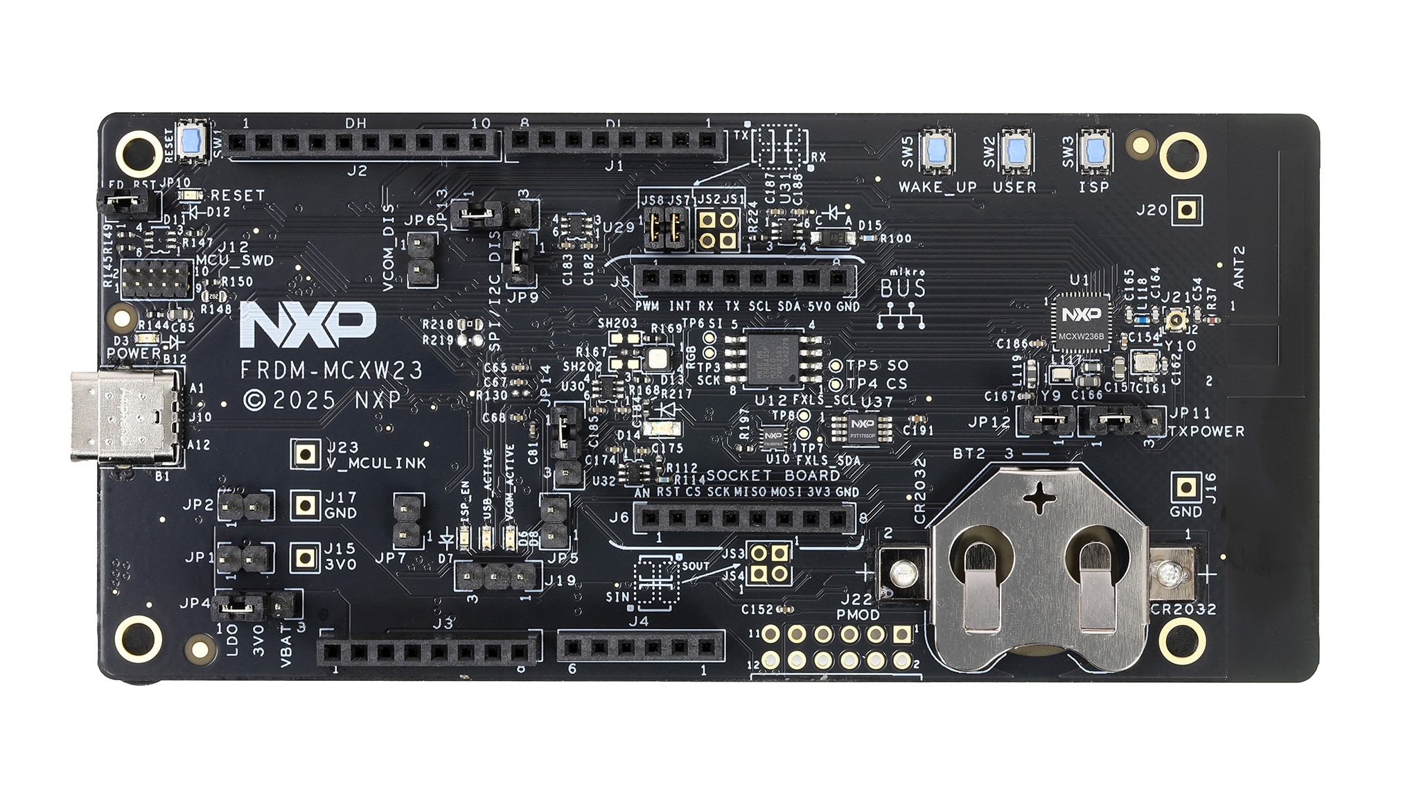
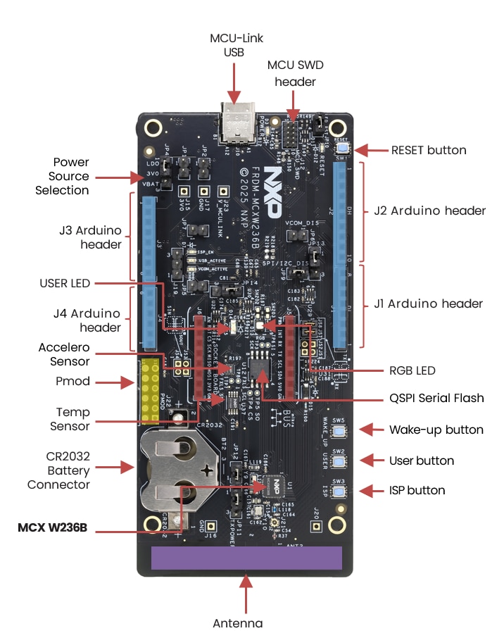
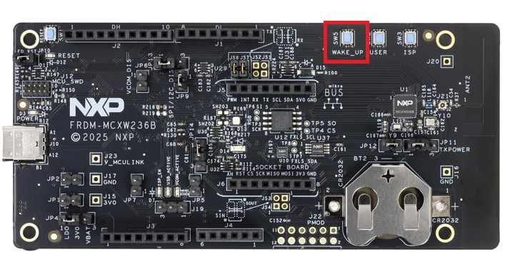
1.1 Get Familiar with the Board
The FRDM-MCXW23 board is pre-programmed with a health care IoT demo. This serves as a sanity check to verify that the device is working as expected out of the box.
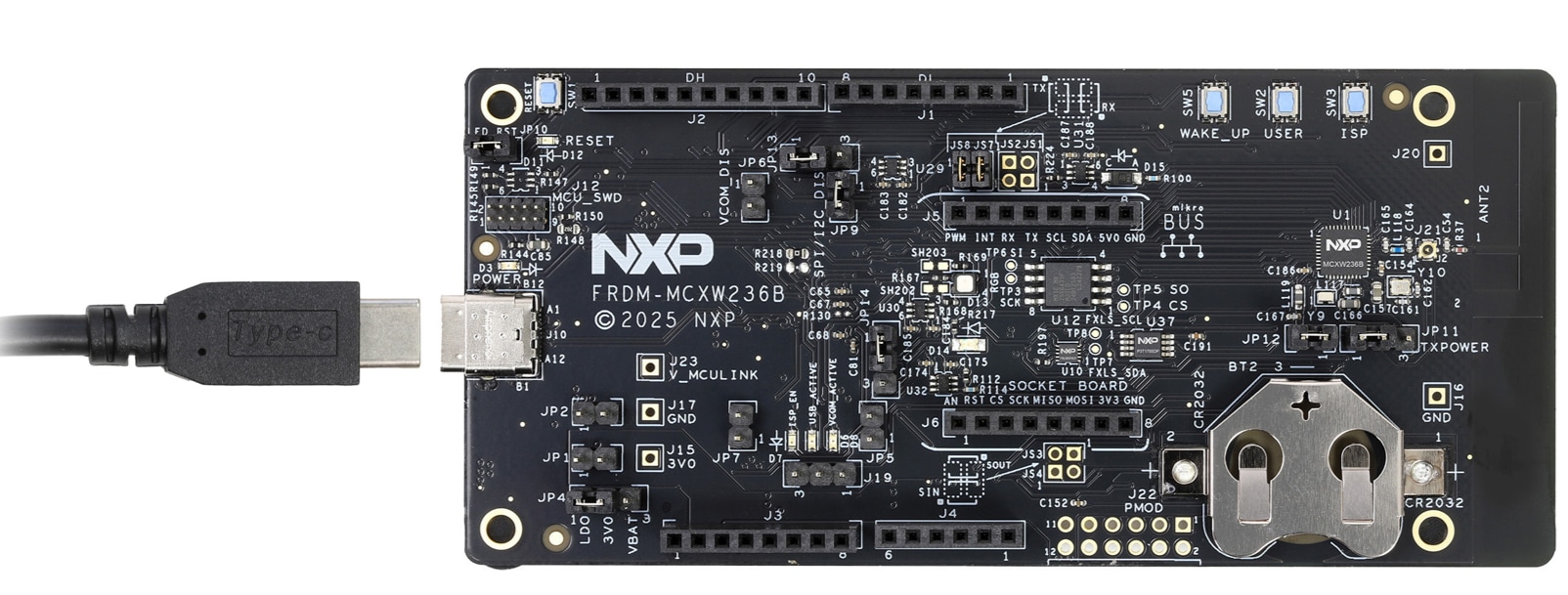
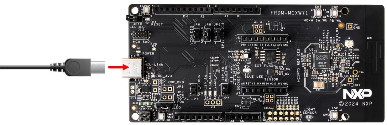
1.2 Plug in the Board
Connect a type-C USB cable from connector J10 to a host computer or power supply to power up the board and run the demo program. Follow the steps shown in the video above to connect and interact with the demo with the NXP's IoT ToolBox.
2. Get Software
2.1 Install your Toolchain
NXP offers a toolchain called MCUXpresso for Visual Studio Code (VS Code). Please download MCUXpresso for VS Code v25.06 or newer.
Learn how to install VS Code for your host PC with the following tutorial.
2.2 Jump Start Your Design with the MCUXpresso MCU NEXT GEN SDK
The NXP extension adds tools to help add software repositories into the VS Code workspace. The software repository is provided from three sources:
- Remote Git URL
- Existing Git folder
This section will explain how to import the MCUXpresso SDK using the remote Git repository option.
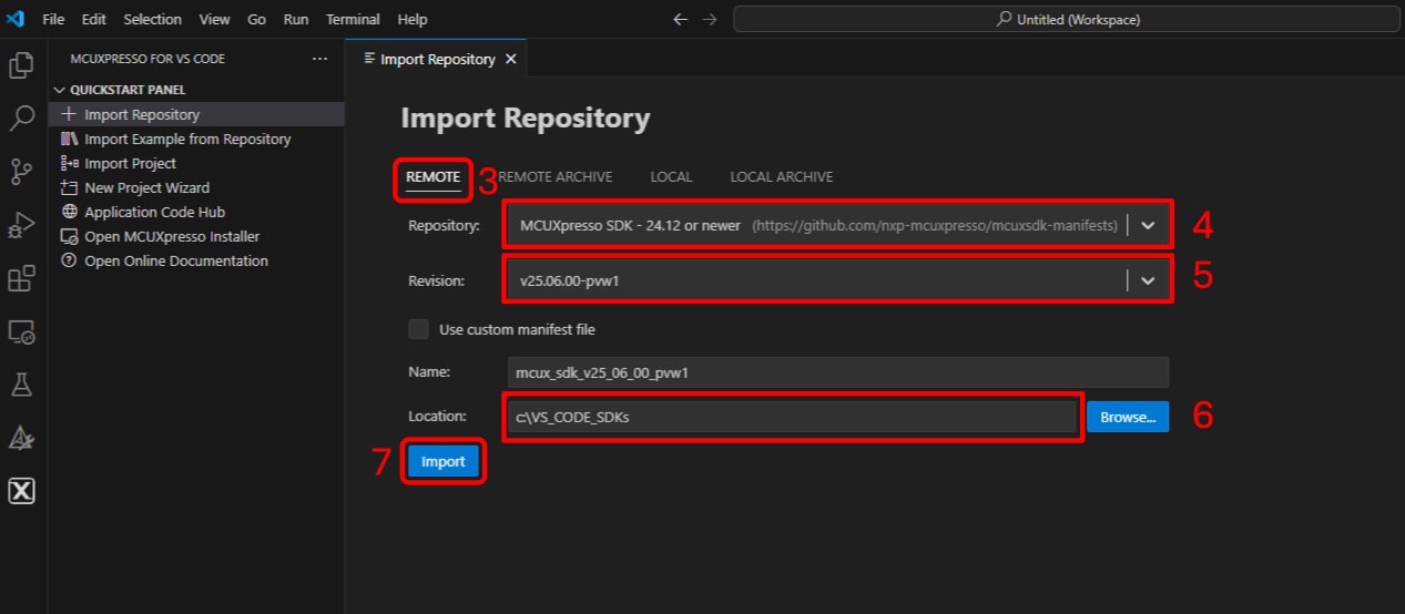
For the remote Git repository option follow these steps.
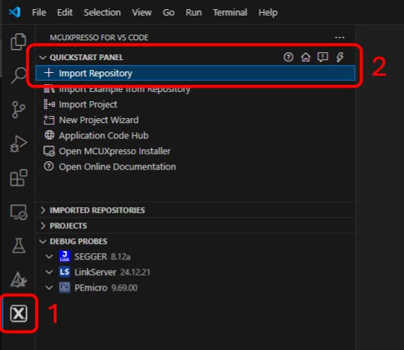
- Click the MCUXpresso extension Icon
- Click the “QUICKSTART PANEL” tab and then click the "Import Repository" button
- After pressing that button a new import window will appear on your integrated development environment (IDE)
- Select the "Remote" option to import the provided SDK files
- Locate the Repository options by clicking the arrow button and search for the "MCUXpresso SDK - 24.12 or newer" option
- Locate the Revision options by clicking the arrow button and search for version "v25.06.00" or newer
- Locate a folder to be a common "Destination" to store SDKs. (i.e. C:\VS_CODE_SDKs) Enter a name for the new
SDK,
in this case
\mcux_sdk_v25_06_00_pvw1 - Click Import button and wait for the installation
2.3 MCUXpresso Config Tools
The MCUXpresso SDK is complimentary, including full source code under a permissive open source license for all hardware abstraction and peripheral driver software. You may install the MCUXpresso SDK directly from the MCUXpresso SDK website at MCUXpresso SDK Builder . Click the button below to open this board's SDK builder.

The MCUXpresso Config Tool is an integrated suite of configuration tools that guides users in creating new MCUXpresso SDK projects, and also provides pin and clock tools to generate initialization C code for custom board support. It is fully integrated as a part of MCUXpresso IDE and also as a separate tool if using a different IDE such as MCUXpresso extension for VS Code.
Click Get MCUXpresso Config Tools below to get the Config Tools installer.
2.4 Programming and Provisioning Tools
The MCUXpresso Secure Provisioning (SEC) Tool is a GUI-based application provided that simplifies generation and provisioning of bootable executables on NXP MCU devices. We recommend that all users to begin with MCUXpresso Secure Provisioning (SEC) tool for trial run and mass production use. It supports secure programming and device provisioning on NXP's microcontrollers at the production stage.
After downloading the tool, you can find the user guide under the ‘Help’ tab. Follow the instructions for your board in the ‘Processor-specific workflow’ chapter.

3. Build, Run
The following steps will guide you through the health care IoT demo application using MCUXpresso IDE for the Cortex-M33 application. The MCUXpresso IDE installation and the SDK for the MCXW-Series can be found at the Get Software section of this Getting Started guide.
Building and Running a Health Care IoT Demo
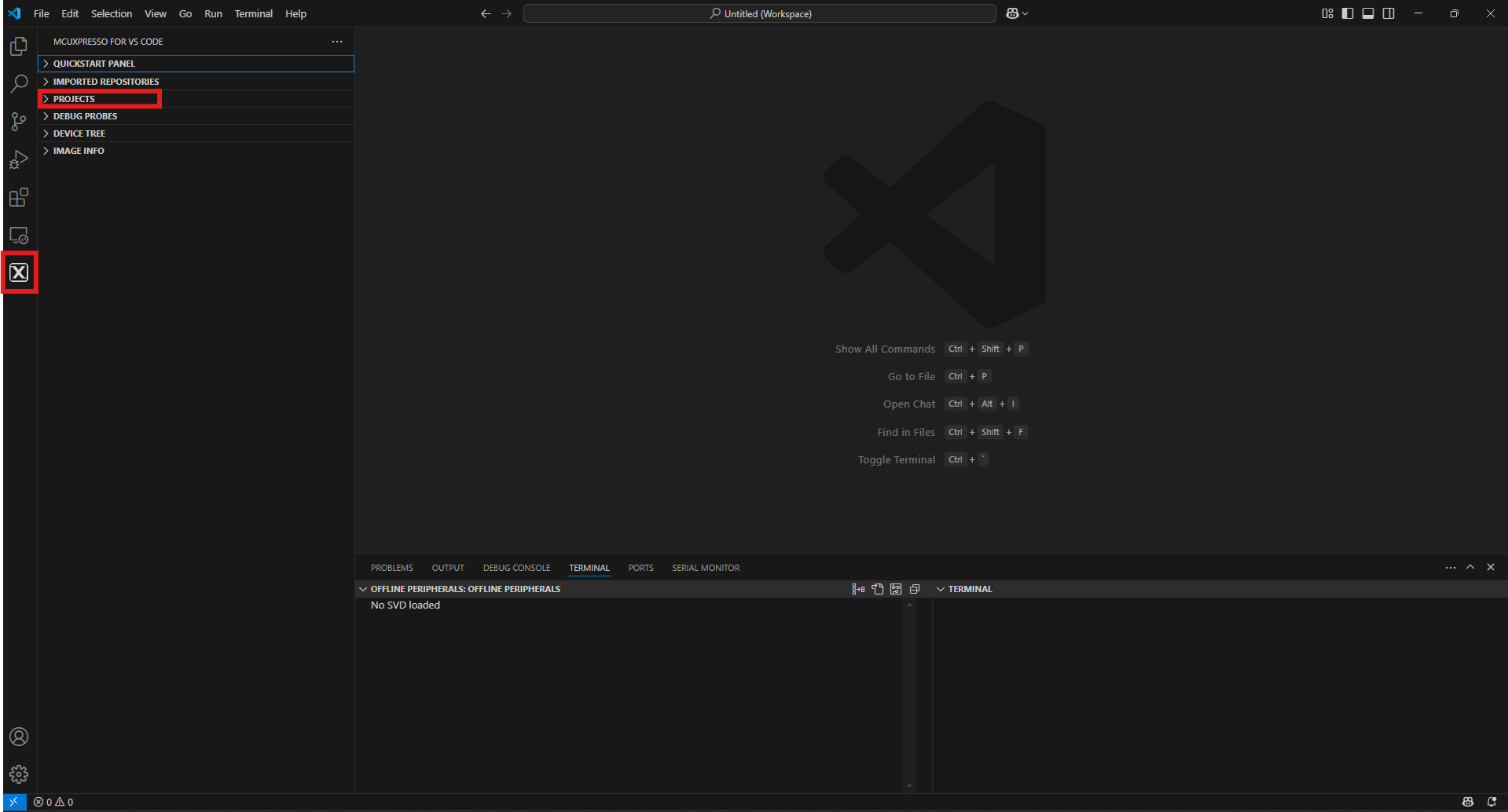
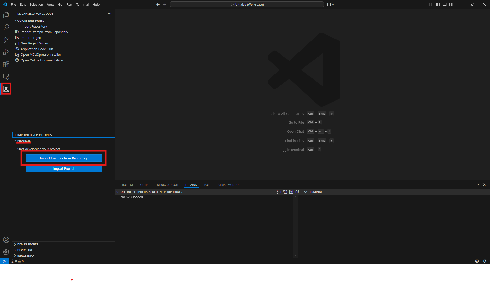
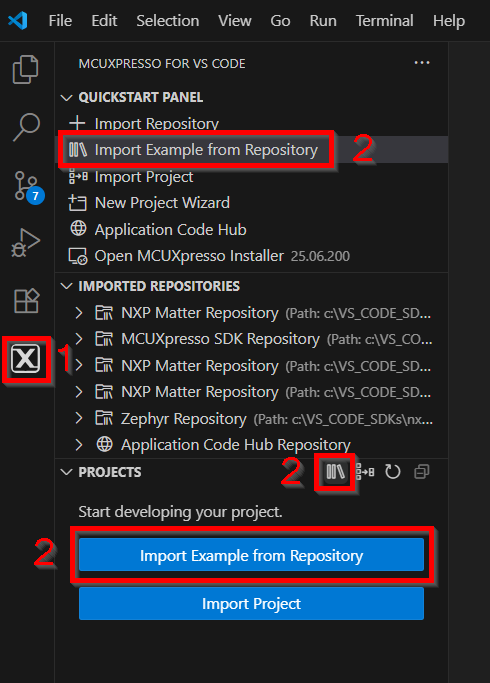
- Find the activity bar in the left-hand bar and click it to open it
- Once it's open go to the explorer and open the project tab
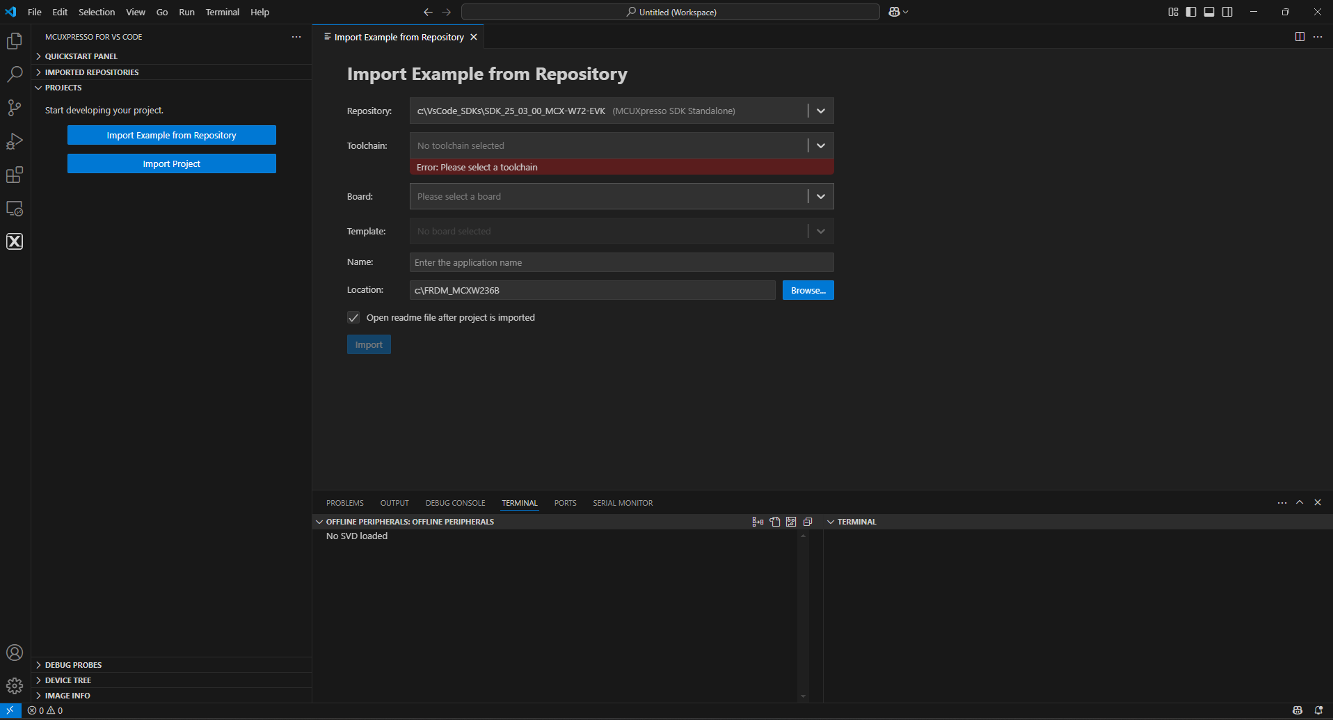
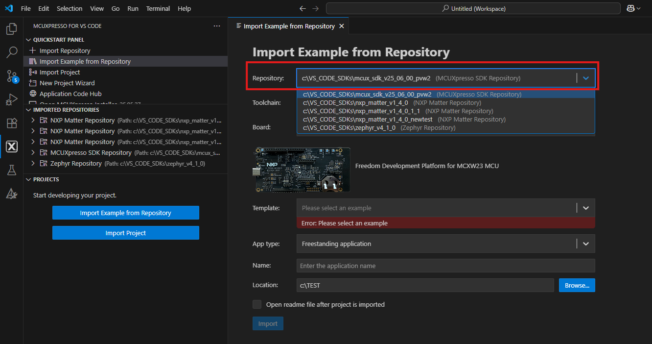
- Then click Import example from the repository
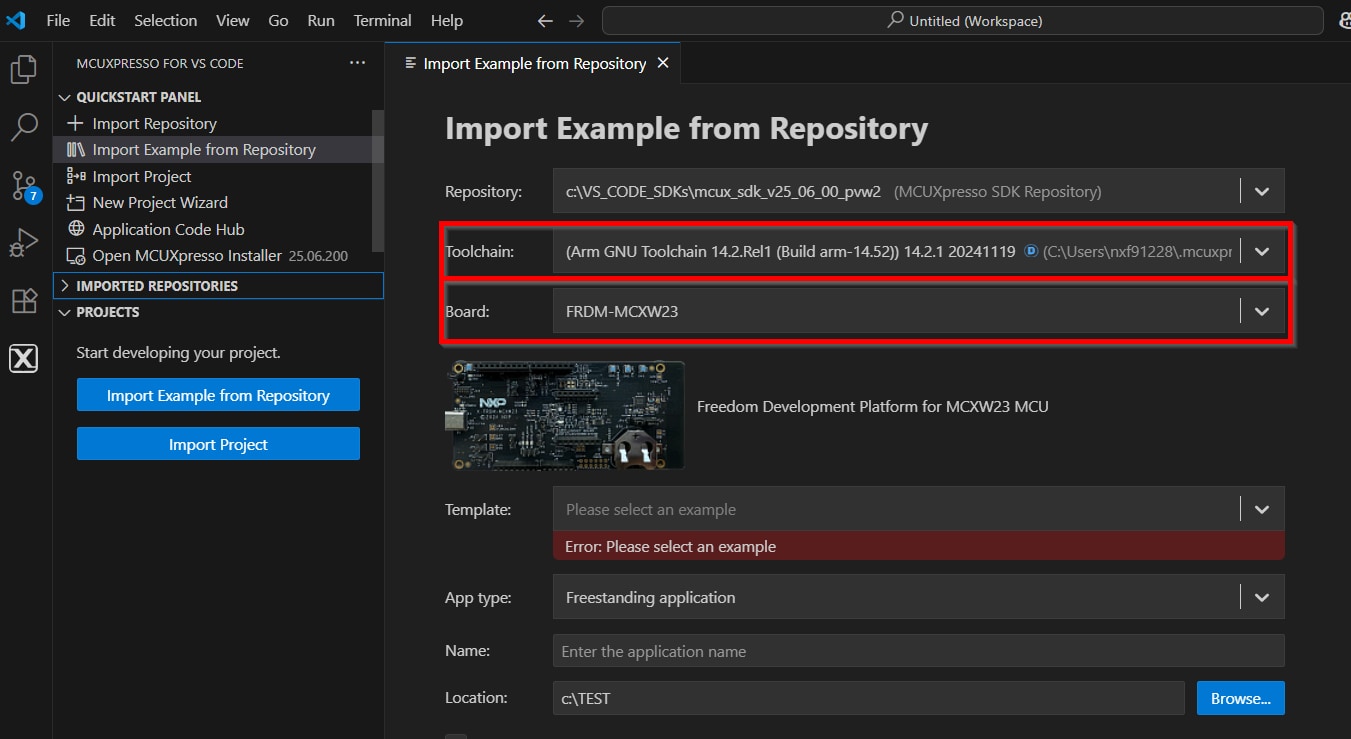
- Click the arrow button on the repository tab to choose your previously download FRDM MCXW-Series board SDK to select an example that can run on that board, and then click Next
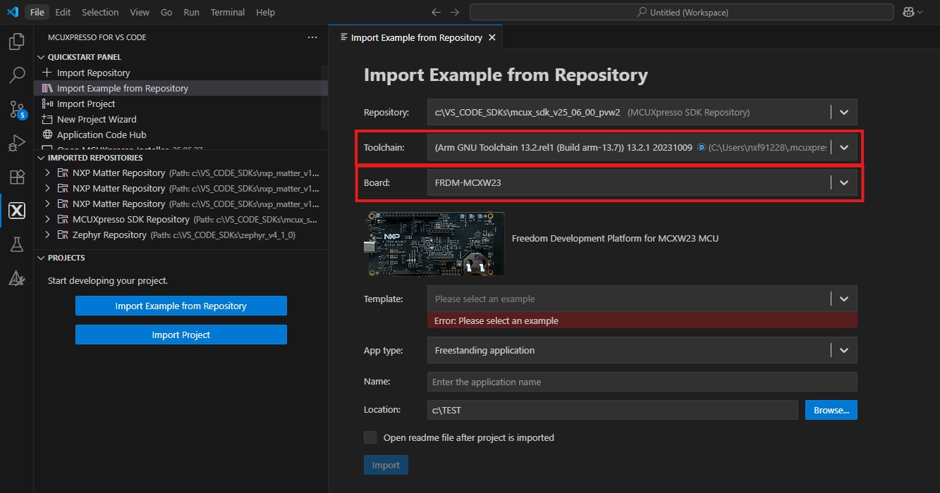
- Select the toolchain acording to the SDK version—both SDK and toolchain must match to avoid problems—then select the board
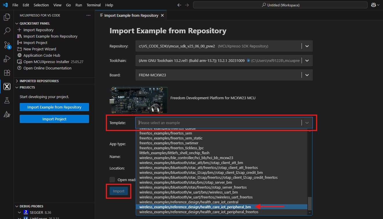
- Use the arrow button to expand the Template tab, and then select the
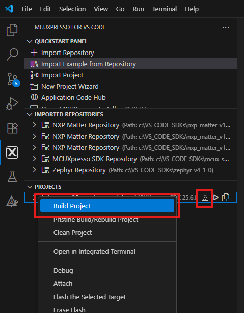
"wireless_examples/reference_design/health_care_iot_peripheral_bm"to use it as a template for the project, then, click import button - Select the project and build it by either clicking the “Build Icon” in the shortcuts provided above, or by doing a right-clicking to select the "Build" option
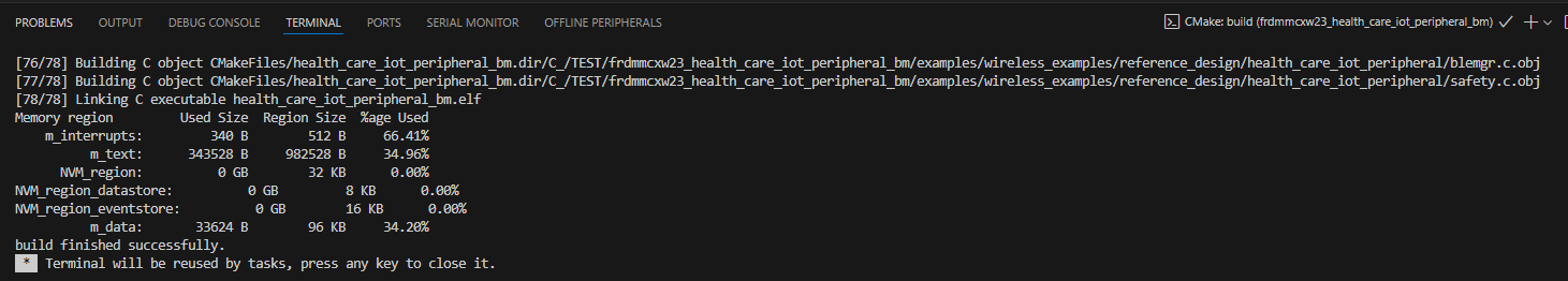
- The project should build without presenting any errors or warnings in the console
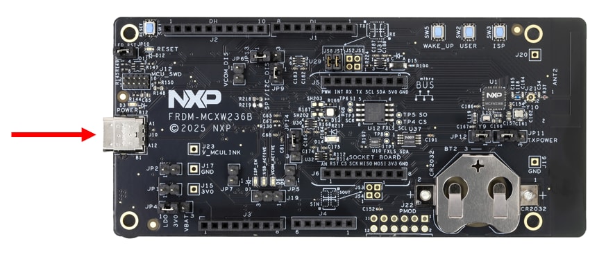
- Connect the board to your computer with the micro-USB to
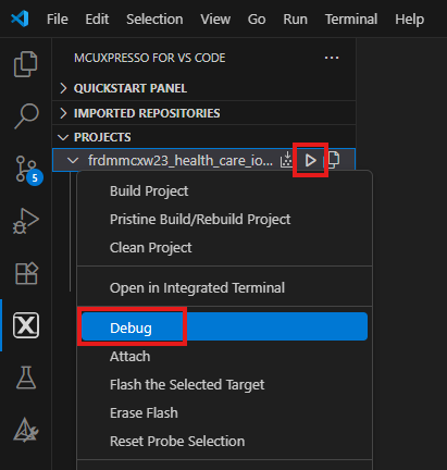
J10'MCU-LINK' port - Download the application to your board by either clicking the “debug” icon, or by doing a right-clicking to select the "Debug" option
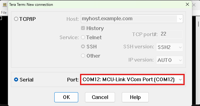
- To see the application's output, open up a serial terminal by selecting the port corresponding to the MCULINK probe to your board “MCULink-VCOM” window.
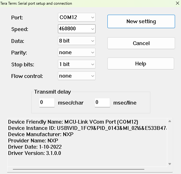
- Set your terminal to boudrate or speed to "460800", 8-bits data, no parity and 1 stop bit, then connect to that port
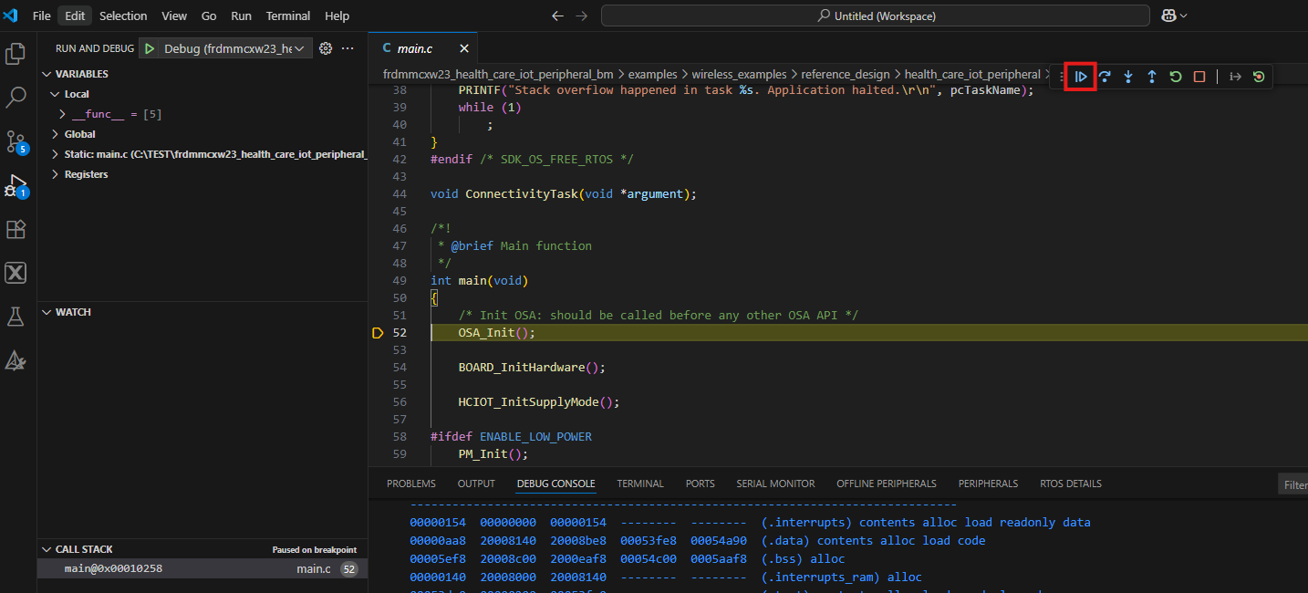
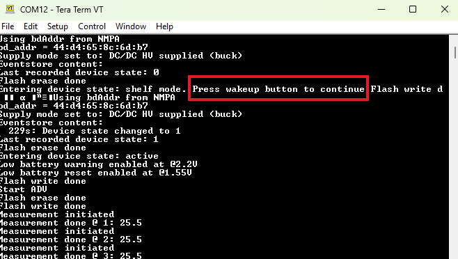
- Run the application by pressing the “run” icon (see the output printed on the terminal)
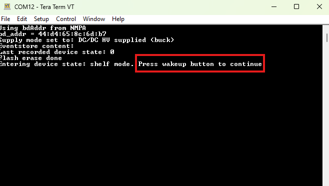
- Press "Wake_up" —labeled as SW2 on the board— to start running the example
- See the output printed on the terminal
- You can connect the demo to the IoT Toolbox app by following the steps shown in the Plug it in video in section 1
The following tab will open on the editor screen
3.1 Build and Flash Application Using MCUXpresso IDE
The following steps will guide you through the health care IoT demo application using MCUXpresso IDE for
the
Cortex-M33 application. The MCUXpresso IDE installation and the SDK for the MCXW-Series can be found at the Get Software section of this
Getting Started guide.
Building and Running a Health Care IoT Demo
- Find the activity bar in the left-hand bar and click it to open it. Once it's open go to the explorer and open the project tab
- Then click Import example from the repository
- Click the arrow button on the repository tab to choose your previously download FRDM MCXW -Series board sdk to select an example that can run on that board, and then click Next.
- Select the toolchain acording to the SDK version, both SDK and toolchain must match to avoid problems. Then select the board
- Use the arrow button to expand the Template tab, and then select
the
"wireless_examples/reference_design/health_care_iot_peripheral_bm"to use it as a template for the project. Then, click import button - Select the project and build it by either clicking the “build icon” in the shortcuts provided above or by doing a right click and select the "Build" option
- The project should build without presenting any errors or warnings in the console
- Connect the board to your computer with the micro-USB to
J10'MCU-LINK' port - Download the application to your board by either clicking the “debug” icon above or by doing a right click and select the "Debug" option
- Open up a serial terminal to be able to see the application’s output. Select the port corresponding to the MCULINK probe to your board “MCULink-VCOM” window. Set your terminal to boudrate or speed to "460800", 8-bits data, no parity and 1 stop bit and connect to that port
- Run the application by pressing the “run” icon. See the output printed on the terminal
- Press on board SW2 label as "Wake_up" to start running the example
- See the output printed on the terminal
- You can connect the demo to the IoT Toolbox app by following the steps shown in the Plug it in video in section 1
The following tab will open on the editor screen.
4. Create
4.1 Modify an Example Project from MCUXpresso for VS Code
The following steps will guide you through the manipulation of the general-purpose outputs. The example sets up a CTimer to generate a Pulse width modulation (PWM) signal and change between two LEDs.
-
Find the activity bar in the left-hand bar, and click to open it then once it's open you can either
- Go to the Explorer and open the Project tab and click on import example application from an imported repository
- Click the import repository icon
- Go to the Quickstart panel and click on Import Example from Repository button
- Click and select the repository for the FRDM-MCXW23 board to select the corresponding toolchain that matches the SDK version
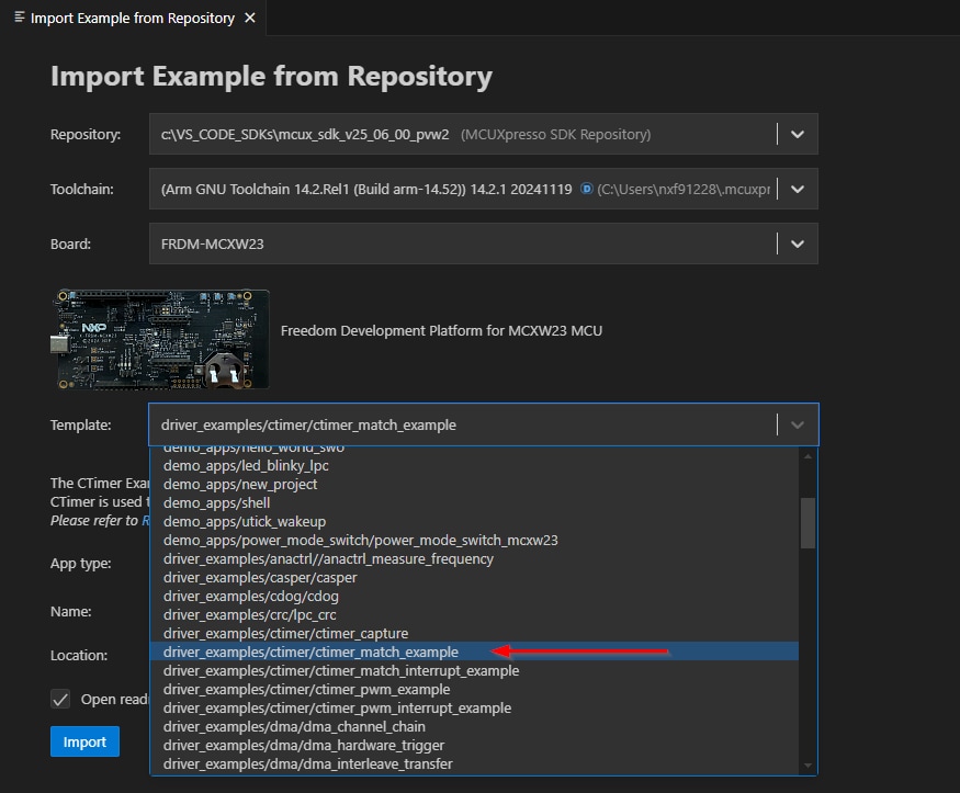
- Use the arrow button to expand the template category, search for
driver_examples/ctimer/ctimer_match_example, click on the line that matches this text to select it, then click on import - Click on the
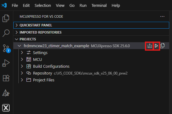
frdmmcxw23_ctimer_match_interrupt_exampleproject in the side bar then compile and run the demo as described in the previous section - You should see the GREEN LED changing back and forth
- Terminate the debug session
4.2 Use MCUXpresso IDE Pins Tools
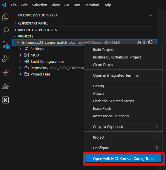
- Open the pins tool by right clicking the project, then selecting the selecting “Open with MCUXpressoConfigTools” button
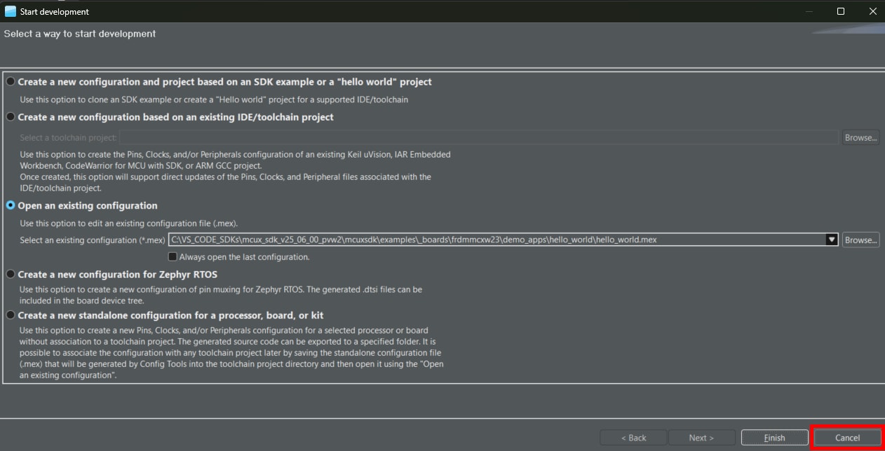
- The pins tool should now display the Start Developing window and then you should search for the .mex file of the project and select it
If this file is included in your project you can search for it in the path: <your_sdk_path>
/mcux/mcuxsdk\examples\_boards\frdmmcxw23\<type_of_project>\<project_name>
For example, in the image shown, the <hello_world> project type has been selected from the <demo_apps> folder within the SDK path. This selection is used to locate the .mex file, which contains the configuration for the project. After selecting the file, click Next, then Finish to proceed.
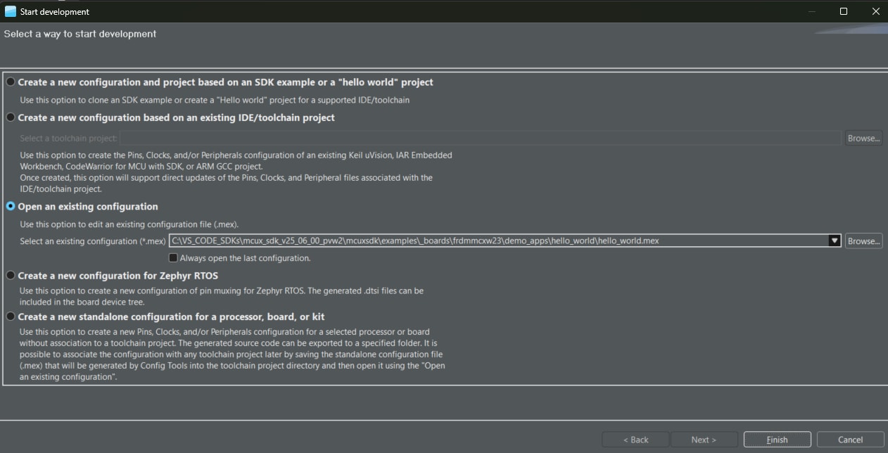
If your imported example project does not have the .mex file present you can just click Cancel button
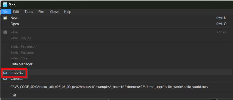
When the next window appears, click the File tab and then click the Import button
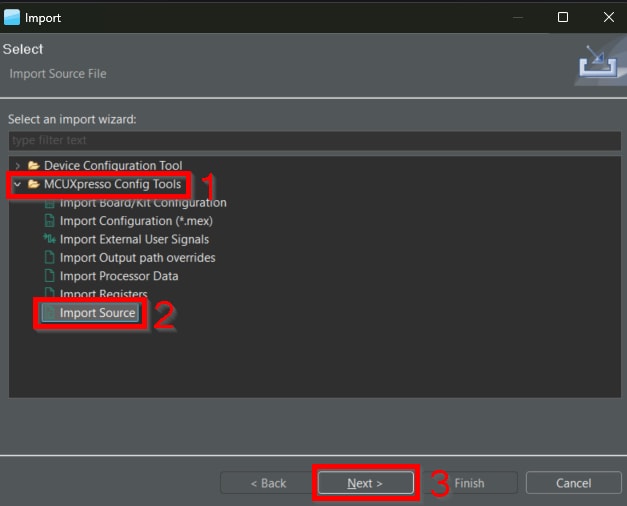
When the new import window pops up, click the "MCUXpresso Config Tools" tab to expand it and then click the "Import Source" button, then click Next
Click to browse for your project path as explained on step 2, then select the "pin_mux.c" file and click Open
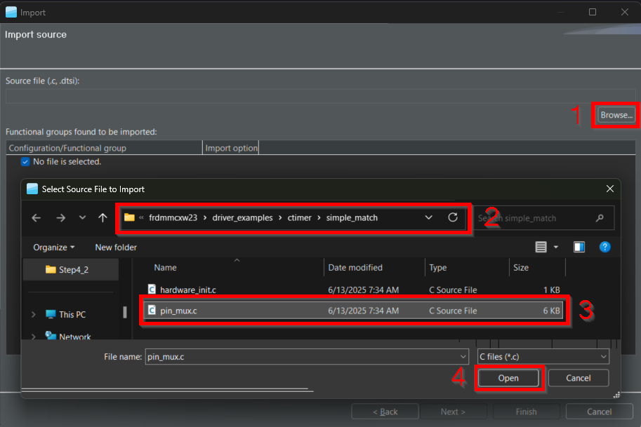
The Import source window should appear as shown in the image, then you can click Finish
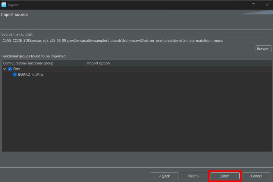
The pins tool should now display the pin configuration for the CTimer project
4.3 Use the Pins Tools to Modify the LED Routed Pin
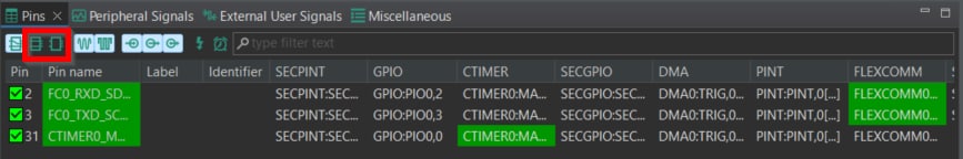
- In the Pins view deselect “Show dedicated pins” and “Show no routed pins” checkboxes to see only the (routed) pins have a check in a green box next to the pin name and the functions selected for each routed pin are highlighted in green
- In the current configuration,
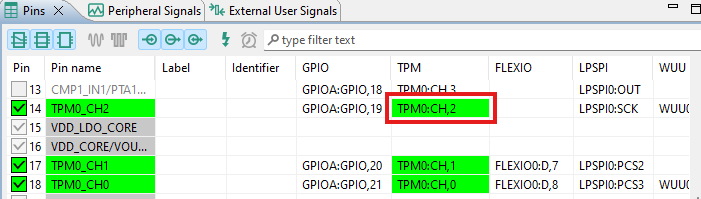
PIO_0is routed as the outputs of the CTimer so now we add the pin configuration to enable the BLUE LED - Select "Show no routed pins" to see the other options, then enable the BLUE LED by searching for
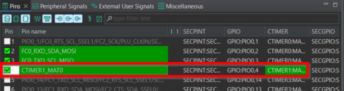
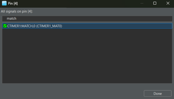
CTIMER1and selectMATCH0under the GPIO column - After clicking the checkbox, this window will appear, then type in the search box "MATCH", then select the
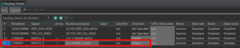
CTIMER1:MATCH,0and click done - Ensure that the pin configuration is set as an output in the “Routing Details” window
- Now, it’s time to implement these changes into the project by exporting the new updated pin_mux.c and pin_mux.h files that were generated by the Pins tool by checking the pin configuration to be set as an output in the “Routing Details” window
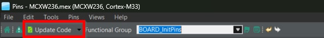
- Now, save your file to proceed to export the new configuration files by pressing either CTRL+S or press on the file tab and click save
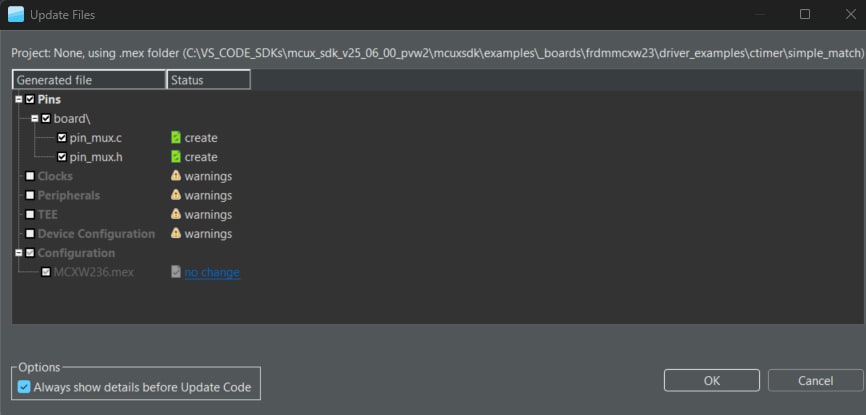
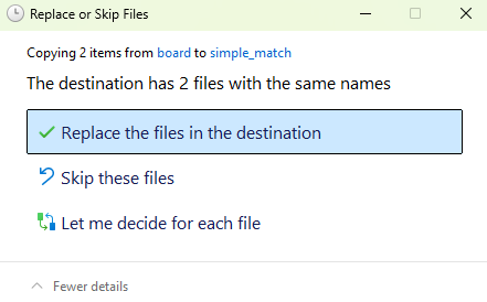
- The screen that pops up will show the files that are changing, allowing you to click “diff” to see the difference between the current file and the new file generated by the Pins tool
- Click “OK” to overwrite the new files into your project.
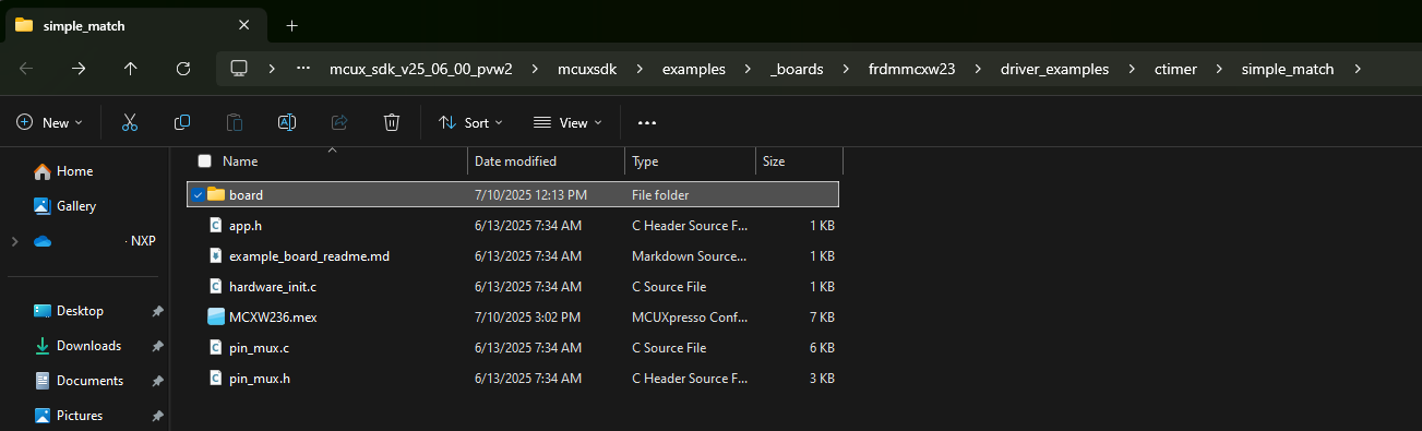
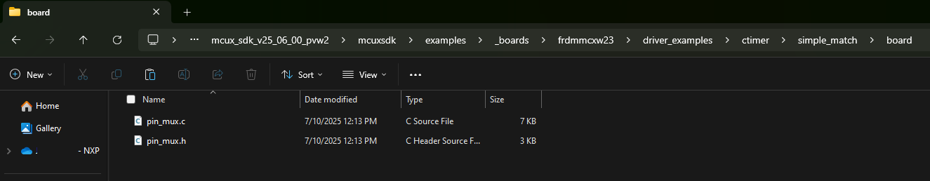
- In this step you replace the new generated files from the tool created inside a new folder called "board"—located in your examples path as shown in previous steps— where you can copy the files from this folder into the original example folder where to change the project files to the new version
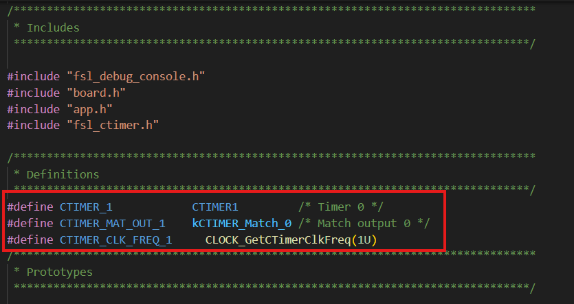
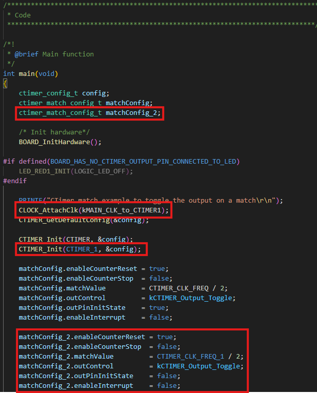
- To add some additional code to the example, you open the
simple_match_interrupt.cfile and add the following macros to initialize the new CTimer, to enable the output for the BLUE LED . - Add the
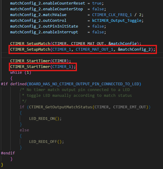
ctimer_match_config_tvariable for the new CTimer configuration, then attached the required clock input for the module, then we will init the timer and start setting the match configuration. - Before the main function, you set up the new CTimer to match configuration, then start the timer
- Build and download the project as shown in the previous section
- When you run the application in this step, you should now see the Green and Blue LED blinking back and forth
- Terminate the debug session
5. MCUXpresso Developer Experience
Check out each of the following sections to learn about the ecosystem NXP provided for flexible prototyping and development. In the video below, we will introduce you to the FRDM platform, the full-featured EVK and the compatible shields for extended capabilities. In addition, we will walk you through our Application Code Hub where we provide numerous application examples through NXP's GitHub.
5.1 FRDM Platform, Full Feature EVK and Shields
For quick prototyping platforms, we offer both the low-cost FRDM platform and the full-featured evaluations kits (EVK)
FRDM Development Boards come with standard form factor and headers, easy access to MCU I/Os, onboard MCU-Link debugger and a USB-C cable. Our full-featured evaluation kits include extended I/O and interface access—extendable with Wi-Fi and additional MCU-Link features. They also include Open Cortex Microcontroller Software Interface Standard (CMSIS) Pack example may be available on ACH, but if not, many of them are easy to use via serial interface like Inter-Integrated Circuit (I²C), Serial Peripheral Interface (SPI), and Universal Asynchronous Receiver-Transmitter (UART) for which we provide drivers with examples in the MCUXpresso SDK.
5.2 Application Code Hub (ACH)
The ACH further enhances our MCUXpresso Developer Experience by giving developers an interactive dashboard to quickly locate software. Visit the ACH today to start exploring or discover additional details and benefits.
Software accessible from ACH is located in NXP’s GitHub repository so it can be easily accessed and cloned directly from that location.
5.3 Demo Walkthrough
In the following video, walks you through importing a project from ACH using a system based on the FRDM platform with a motor control shield and a low-cost LCD. Although your evaluation board may differ from this system, the following steps can be replicated and used for all the supported platforms.
System Design Guides
Terminal Application
MCUXpresso IDE Terminal Tutorial
The most recent versions of MCUXpresso IDE count with a terminal emulation application. This tool can be used to display information sent from your NXP development platform's virtual serial port.
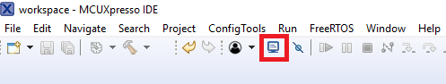
- Open the MCUXpresso IDE
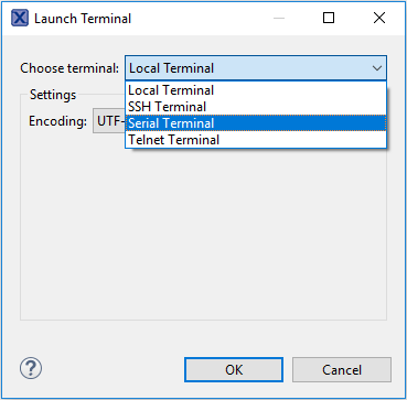
- Launch the MCUXpresso IDE terminal by clicking on the "Open a Terminal" button on the top of the IDE or press "Ctrl + Alt + Shift + T"
- Select Serial Terminal
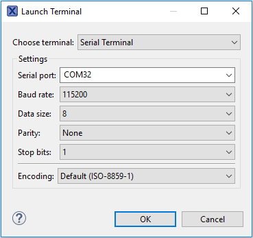
- Configure the serial port settings (using the LPC-Link2 COM port number) to 115200 baud rate, 8 data bits, no parity and 1 stop bit, then press the "OK" button
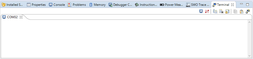
- Verify that the connection is open. If connected, MCUXpresso IDE will look like the figure below at the Terminal view
- You're ready to go
Tera Term Tutorial
Tera Term is a very popular open source terminal emulation application. This program can be used to display information sent from your NXP development platform's virtual serial port.
- Download Tera Term from SourceForge. After the download, run the installer and then return to this webpage to continue
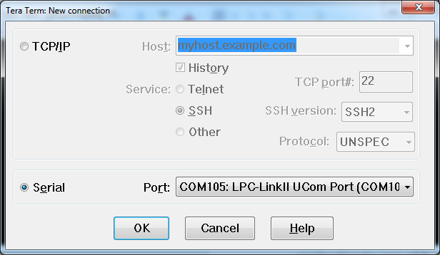
- Launch Tera Term. The first time it launches, it will show you the following dialog. Select the serial option. Assuming your board is plugged in, there should be a COM port automatically populated in the list
- Configure the serial port settings (using the COM port number identified earlier) to 115,200 baud rate, 8 data bits, no parity and 1 stop bit. To do this, go to Setup → Serial Port and change the settings
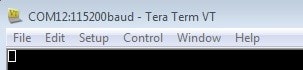
- Verify that the connection is open. If connected, Tera Term will show something like below in its title bar
PuTTY Tutorial
PuTTY is a popular terminal emulation application. This program can be used to display information sent from your NXP development platform's virtual serial port.
- Download PuTTY using the button below. After the download, run the installer and then return to this webpage to continue
- Launch PuTTY by either double clicking on the *.exe file you downloaded or from the Start menu, depending on the type of download you selected
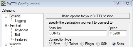
- Configure In the window that launches, select the Serial radio button and enter the COM port number that you determined earlier. Also enter the baud rate, in this case 115,200
- Click Open to open the serial connection. Assuming the board is connected and you entered the correct COM port, the terminal window will open. If the configuration is not correct, PuTTY will alert you
- You're ready to go
Toolchains
Running a Demo Using IAR Embedded Workbench
The following steps will guide you through opening the hello_world application. The
instructions for compiling and debugging the Cortex M33 core are covered in the instructions below.
Build an Example Application
Please use IAR Embedded Workbench for Arm version 9.50.1 or above.
- First, unzip the previously downloaded FRDM-MCXW71 SDK package
-
Open the desired example application workspace. Most example application workspace files can be located using the following path:
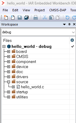
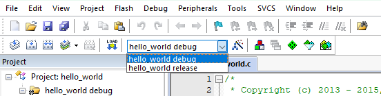
<install_dir>/boards/<sdk_board_name>/<example_type>/<application_name>/iar - Select the desired build target from the drop-down. For this example, select the "hello_world - debug" target
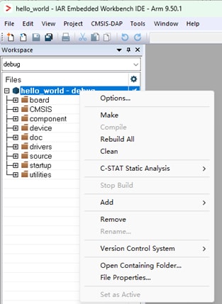
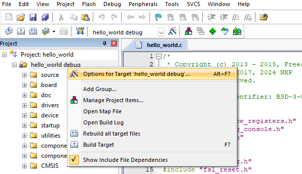
- Open the project properties by doing a right-click on the project and selecting "Options"
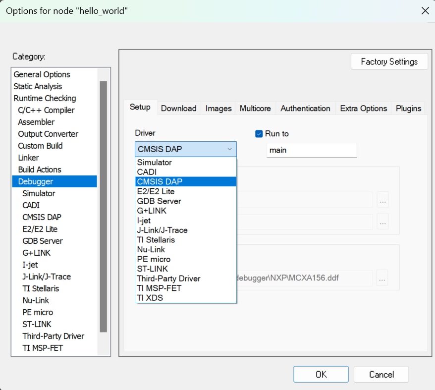
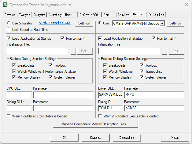
- Now, go to the "Debugger" section and change the debugger driver to CMSIS DAP. Press the OK button
- To build the application, click the "Make" button, highlighted in red below
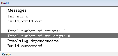
- The build will complete without errors

Run an Example Application
- Connect the development platform to your PC via USB cable to
J10'MCU-Link' port - Click the "Download and Debug" button to download the application to the target
- The application is then downloaded to the target and automatically runs to the main() function
- Run the code by clicking the "Go" button to start the application
- The
hello_worldapplication is now running on the Cortex-M33


Running a Demo Using Keil® MDK/μVision®
Install CMSIS Device Pack
After the MDK tools are installed, Cortex® Microcontroller Software Interface Standard (CMSIS) device packs must be installed to fully support the device from a debug perspective. These packs include things such as memory map information, register definitions and flash programming algorithms. Follow these steps to install the appropriate CMSIS pack. Please use MDK-Arm Microcontroller Development Kit (Keil)® version 5.38.1 or above.
- Open the MDK IDE, which is called µVision. Inside the IDE, select the "Pack Installer" icon
- In the Pack Installer window, search for "MCXW" to bring up the MCXW71 family. Click on the
MCXW7XX name, and then in the right-hand side you'll see the NXP:
MCXW71_DFPpack. Click on the "Install" button next to the pack. This process requires an internet connection to successfully complete - After the installation finishes, close the Pack Installer window and return to the µVision IDE

Build the Example Application
The following steps will guide you through opening the hello_world application. These
steps may change slightly for other example applications as some of these applications may have
additional layers of folders in their path.
-
If not already done, open the desired demo application workspace in:
<install_dir>/boards/<sdk_board_name>/<example_type>/<application_name>/mdk - Select Debug configuration
- Do right-click on the project and select the project options:
- Now, go to the Debug option and select CMSIS-DAP ARMv8-M Debugger. Click on the OK button
- To build the demo project, select the "Rebuild" button, highlighted in red
- The build will complete without errors

MCUXpresso for VS Code
Build and Run an Example with VS Code
Getting Started with MCX W Family
Prerequisites
This example is written for Windows 10, but MCUXpresso for Visual Studio Code can also be easily installed on MacOS and Linux.
- Follow software installation for MCUXpresso for VS Code extension
- Download or receive MCUXpresso SDK for FRDM-MCXW71 (
SDK_2_16_000_FRDM-MCXW71.zip)
Hardware Requirements
- FRDM-MCXW71
- 1 x Type-C USB Cable
Preparing the Hardware
This lab targets the NXP MCX W Evaluation Kit (FRDM). The kit provides a rich set of connected peripherals to help evaluate the device. It includes an onboard Debug Probe. The Debug Probe is pre-programmed with CMSIS-DAP firmware for this lab. To display debug messages in the examples, the lab connects to the COM port available through the same Debug Probe.

Open MCUXpresso for VS Code
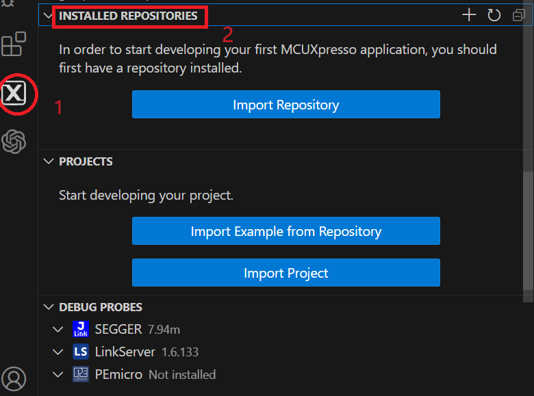
- Open Visual Studio Code, click on the MCUXpresso icon [x] on the left panel
- To move forward with the next step click on "Installed Repositories" panel that will appear as shown in the picture below
Add NXP MCUXpresso SDK
The NXP extension adds tools to help add software repositories into the Visual Studio Code workspace. The software repository can be provided from three sources:
- Remote Git URL
- NXP MCUXpresso SDK archive file
- Existing Git folder
This section will import the MCUXpresso SDK for the MCX W microcontroller using the SDK archive file provided as prerequisite.
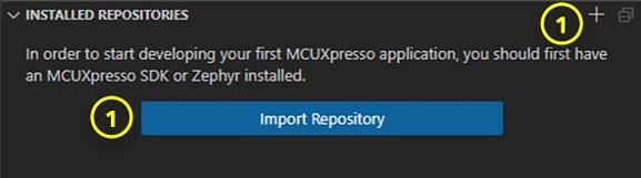
- Click the "Import Repository" button in the "Installed Repositories" panel. A button is visible before the first repository is added. In the future, users could click the '+' symbol in the top right of the Installed Repositories section for adding repositories
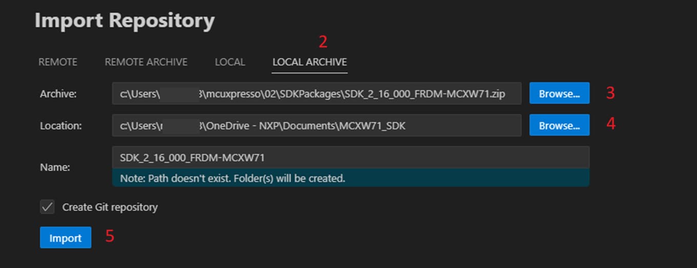
- Select the "Local Archive" option to import the provided MCX W SDK archive file
- Browse to the location of the MCX W SDK file for the "Archive" entry (in the Downloads folder)
- Browse to a folder to be a common "Destination" to store SDKs (i.e.
C:\Users\NXP\Desktop\VSCODE_SDK). Enter a name for the new SDK, in this case:SDK_2_16_000_FRDM-MCXW71 - Click Import. The MCX W SDK is extracted to the local folder and added to your "Installed Repositories" panel
Import Example Project
The NXP extension provides a "Projects" pane to help developers import projects into their workspace. The user has three sources for importing a new project: a Repository; an existing local project; or an archived project. This section will import an MCX W example from the SDK just added to the "Installed Repositories" panel.
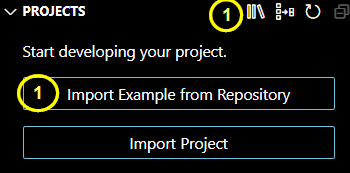
- Click Import Example from Repository. A button is visible when no projects are in the current workspace. In the future, the symbols in the top right of the Projects section can be used to import additional projects. Click the '[II\]' symbol to add Repository Examples. Click the '[+]' symbol to import projects on the PC that were created earlier by the MCUXpresso for VS Code extension. Click the '[ ]' symbol to import a project in an archive file created earlier by the MCUXpresso for VS Code extension
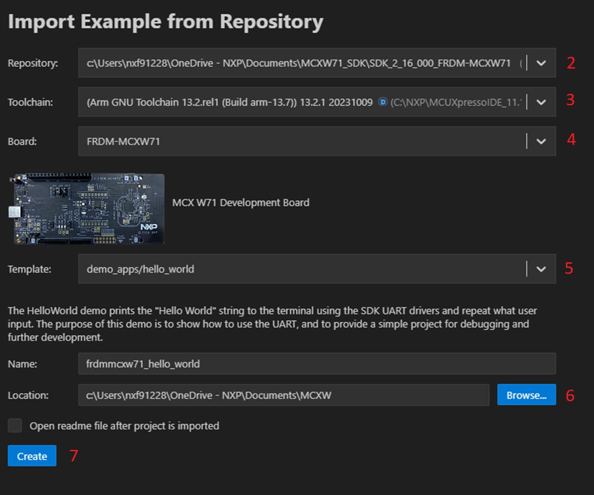
- Fill out the appropriate information in the "Import Example from Repository" window. Click "Choose a Repository" to select from a list of available/installed repositories. Select
SDK_2_16_000_FRDM-MCXW71 - Click "Choose a Toolchain" to select from a list of available build tools. The MCUXpresso Installer provides a default option of
gcc-arm-none-eabi-13.2.1. The tool also looks in other default locations for MCUXpresso IDE installations. These may be listed as alternative options for GNU Arm Toolchains. Select thegcc-arm-none-eabi-13.2.1option - Click "Choose a Board" to view the boards supported in the selected repository. A longer list of boards can be filtered by typing in the available selection area. Select "FRDM-MCXW71". After a board is selected, a picture of the board will be displayed to help confirm the correct selection
- Click "Choose a Template" to show a list of available examples in the selected repository. The long list of examples can be filtered by typing in the available selection area (i.e. type Hello to filter Hello World examples). Select
demo_apps/hello_world - Click Browse for the "Location" field. Choose a folder location for new projects to be created
- Click "Create". This will add a new "Hello World" example for the MCX W to your "Projects" panel
Build Project
The build process is configured when the project is created. The user can initiate the build from an icon in the project view. To the right of the project name, the build icon will start the build for that project. You need to return to the MCUXpresso extension perspective by clicking the “X” icon in the left navigation pane. You may still be in the Explorer perspective from prior section.
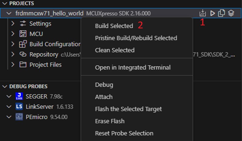
- Click the build icon to the right of the
hello_worldproject. This will start the build process. The "Output" terminal tab at the bottom of the screen displays the build progress - Alternatively, you can right-click on the project name to display additional build options. Clicking "Rebuild" or "Clean Build" will remove build artifacts from prior builds to allow the project to be built again. Otherwise, clicking "Build Selected" will result in an output of "no work to do"
The build process should complete with an exit code of 0… Success!
Flash and Debug Project
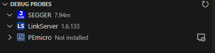
MCUXpresso for Visual Studio Code allows users to program and debug projects for NXP microcontrollers. These steps require that Debug Probe drivers are properly installed and configured. MCUXpresso for Visual Studio Code allows the use of popular debug probes from NXP, SEGGER and PEmicro. MCUXpresso Installer included the option to properly install support for the different debug probes.
The built project output binary is flashed to the target board before launching a debug session. The Debug session provides controls and views to help the developer analyze the operation of the project. The following steps will show how to successfully flash and program the MCX W FRDM Evaluation Kit.
- Confirm that the onboard debug probe is connected to the PC USB port
- Click the "Refresh" arrow in the "Debug Probes" pane to detect connected Debug Probes
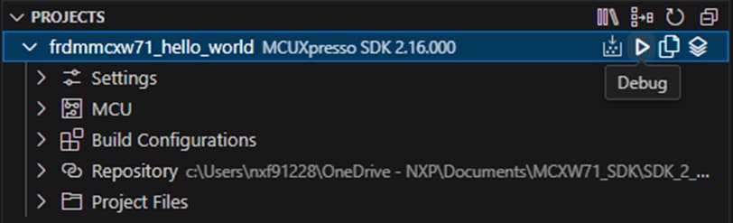
Starting a Debug session begins by programming the target device with the built project image. Click the common "Play" triangle icon to the right of the selected project
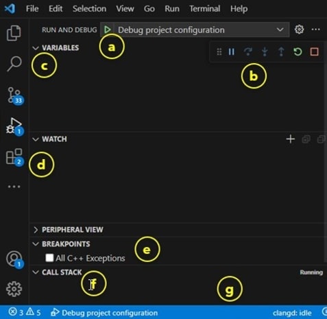
Visual Studio Code Debug sessions provide a different "Run and Debug" perspective for the user. This is reflected by the "Bug" icon in the primary left navigation pane now being highlighted. Key tools are labeled in the following image:
- Start Debug: Another place to launch debug
- Debug Controls: Pause; Step Over; Step Into; Step Over; Restart; Stop
- Variables: Locals and Registers
- Watch: Add expressions to continue to monitor
- Breakpoints: Add, Toggle and View targeted code
- Call Stack: List of active subroutines in the program
- Status Ribbon: Bottom of screen changes status text and/or color to orange
Debugger Firmware
SEGGER J-Link Tutorial
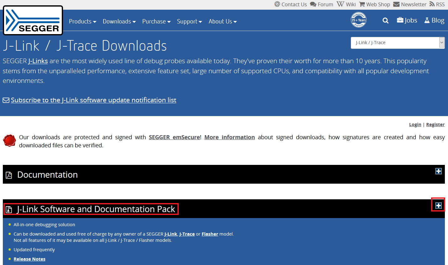
- Download J-Link Software. Enter to SEGGER download page: SEGGER Downloads
- Expand "J-Link Software and Documentation Pack" section
-
Select the software that matches your OS and download the newest version
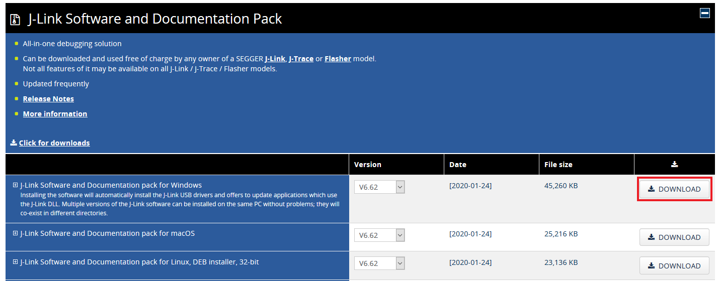
Accept the Terms and download the software
- Execute the
.exefile you just downloaded by doing double-click. Follow the setup instructions until the J-Link installation is complete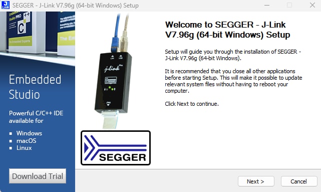
- You're ready to go
Design Resources
Support
Forums
Connect with other engineers and get expert advice on designing with the FRDM-MCXW23 on one of our community sites.
On this page
- 2.1
Install your Toolchain
- 2.2
Jump Start Your Design with the MCUXpresso MCU NEXT GEN SDK
- 2.3
MCUXpresso Config Tools
- 2.4
Programming and Provisioning Tools