Getting Started with MCXW23-EVK
Contents of this document
-
Plug It In
-
Get Software
-
Build and Run
-
Create
-
MCUXpresso Developer Experience
Sign in to save your progress. Don't have an account? Create one.
Purchase your MCXW23 EVK Development Kit
1. Plug It In
Let's take your evaluation kit (EVK) board for a test drive. In follow the steps, you may either watch the sequence in a short video, or following the detailed actions listed below.
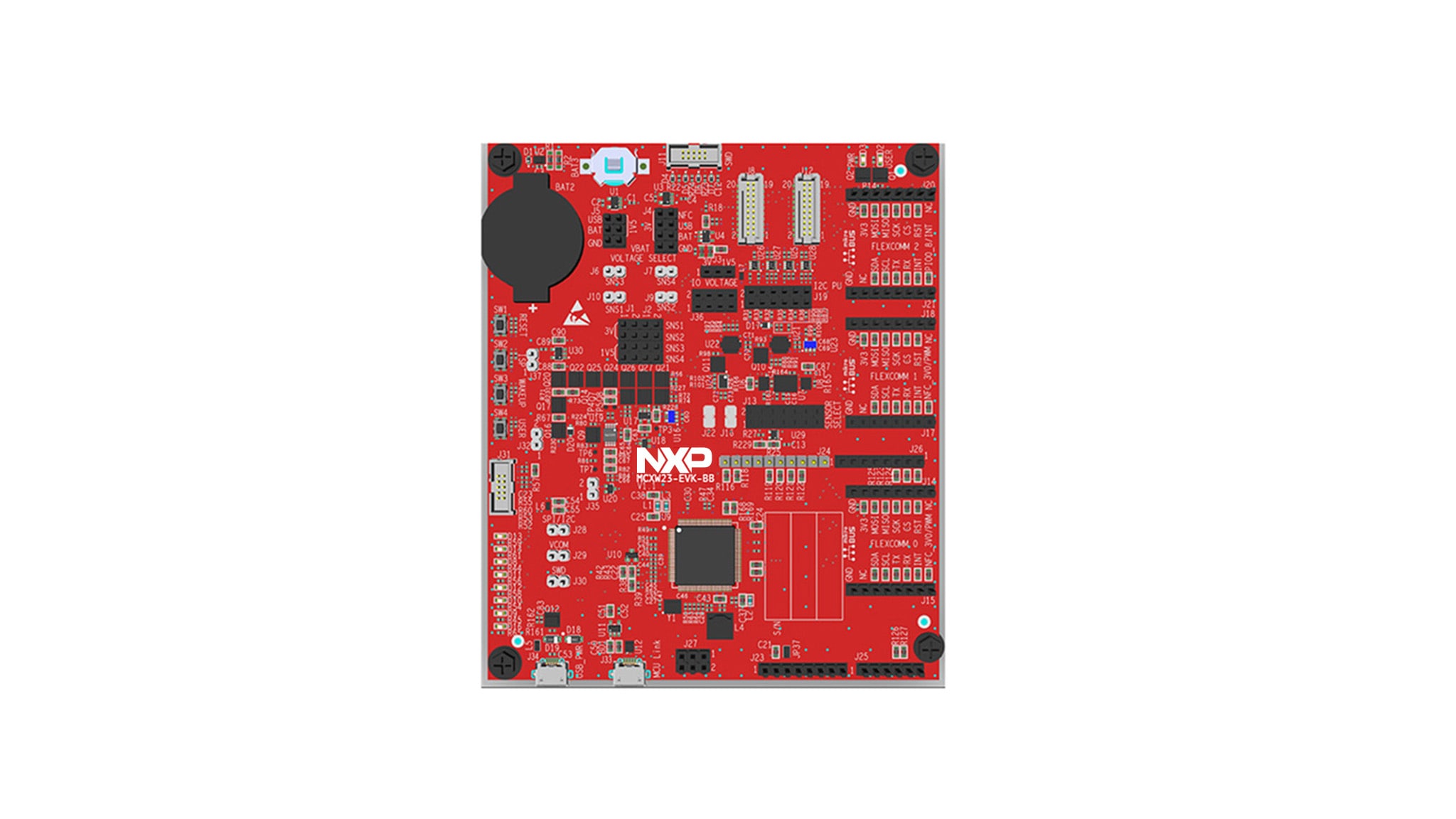
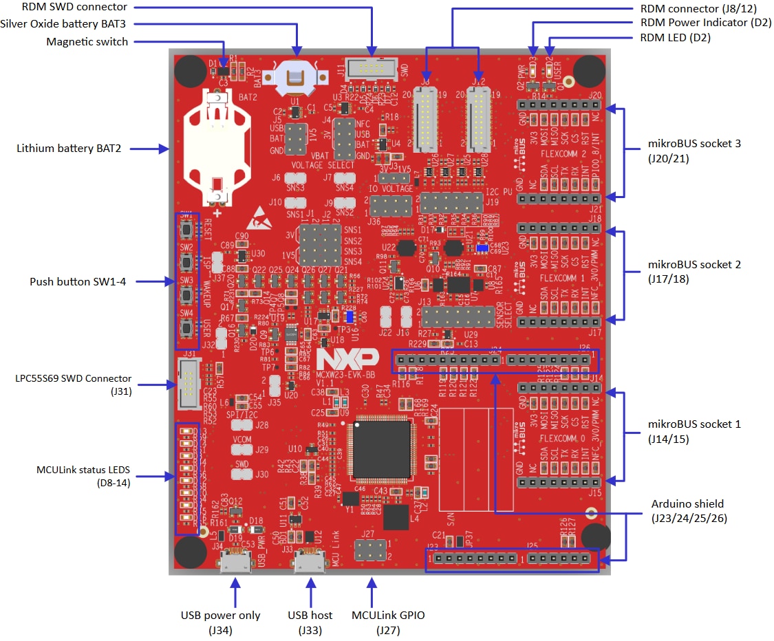
1.1 Get Familiar with the Board
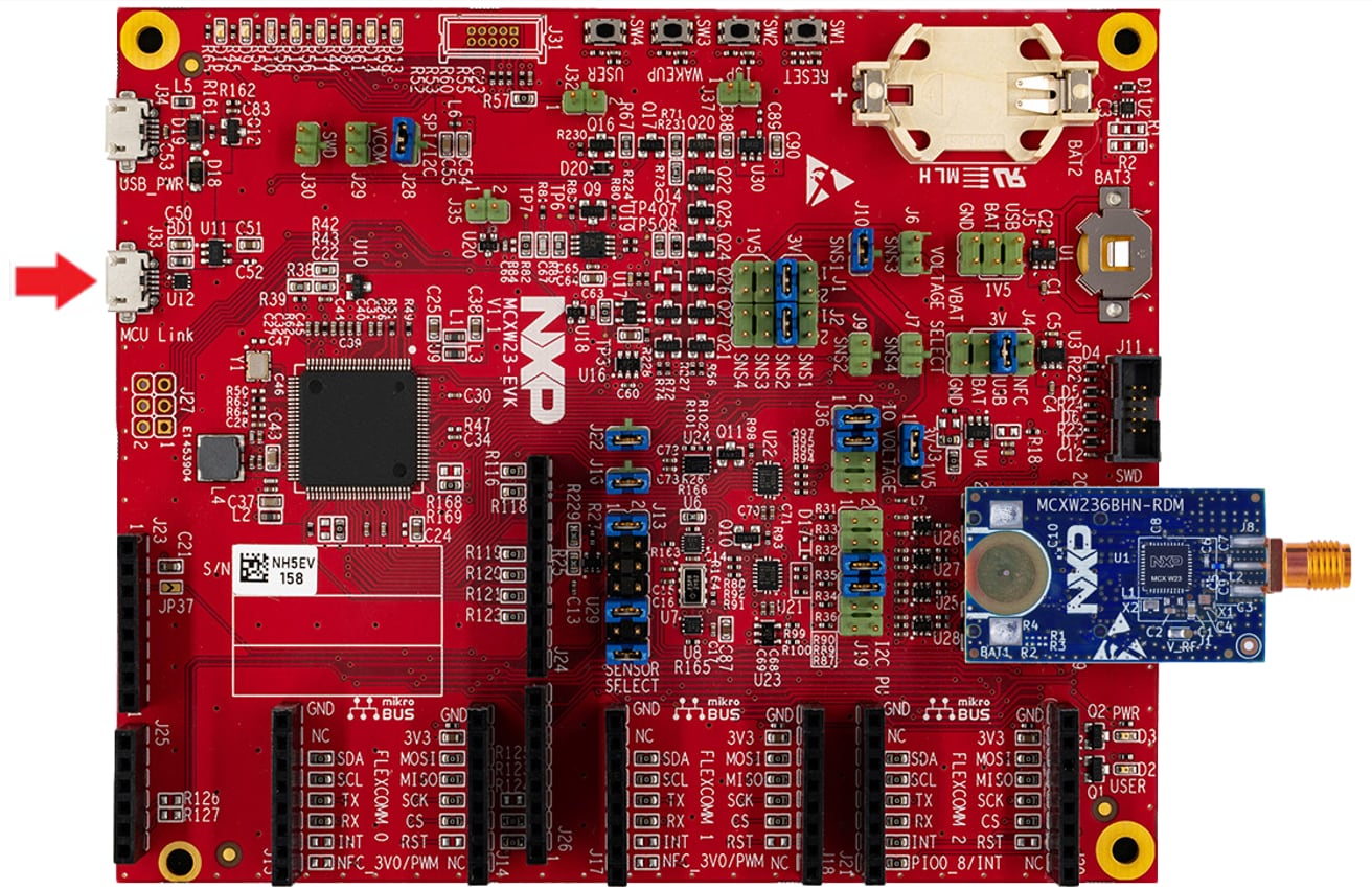
The MCXW23-EVK board is bundled with the MCXW236BHN-RDM board, which comes pre-programmed with a healthcare IoT demo. This demo serves as a sanity check to verify that the device functions as expected, right out of the box.
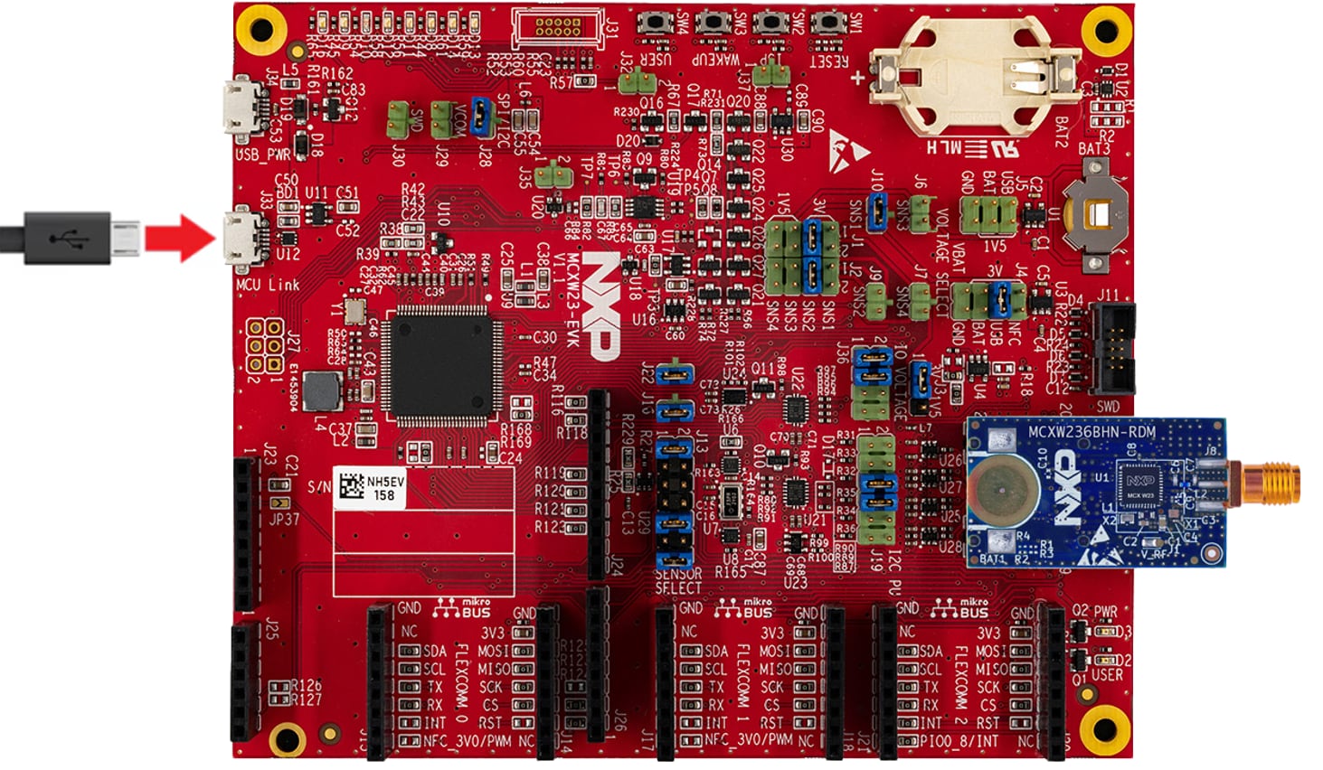
1.2 Set Up the Boards
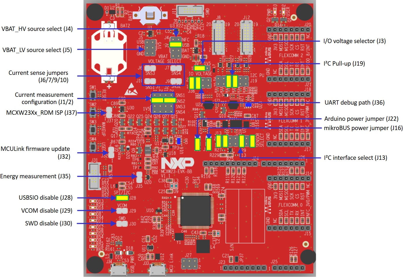
Connect the MCXW23-EVK board to the MCXW236B-EVK-BB by aligning the connector pins from the radio device module (RDM) board connector J6 and J7 to J8 and J12 respectively, but before plugging in the board, make sure to set up the correct jumper settings on the MCXW236B-EVK-BB.
The image below is your reference for the correct jumper settings when connecting the MCXW236BHN-RDM board to the MCXW23-EVK.
1.3 Plug In the Board
Use a USB Type-C cable to connect the board via connector J33 to a host computer or power supply to power up the board and run the demo program.
Follow the steps shown in the video above to connect and interact with the NXP IoT ToolBox demo.
If a password is required to connect to the device, enter this code: 999999.
2. Get Software
2.1 Install Your Toolchain
NXP offers a toolchain called MCUXpresso for Visual Studio Code (VS Code). Please download MCUXpresso for VS Code v25.06 or higher by clicking the button below.
Follow the tutorial to install the toolchain to your host PC.
2.2 Jump Start Your Design with the MCUXpresso SDK
The NXP extension provides tools that add software repositories to the VS Code workspace. The software repository can be accesed from three sources:
- Remote Git URL
- NXP MCUXpresso SDK archive file
- Existing Git folder
This section will show you how to import the MCUXpresso SDK using the remote Git repository in the following steps:
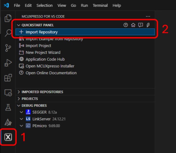
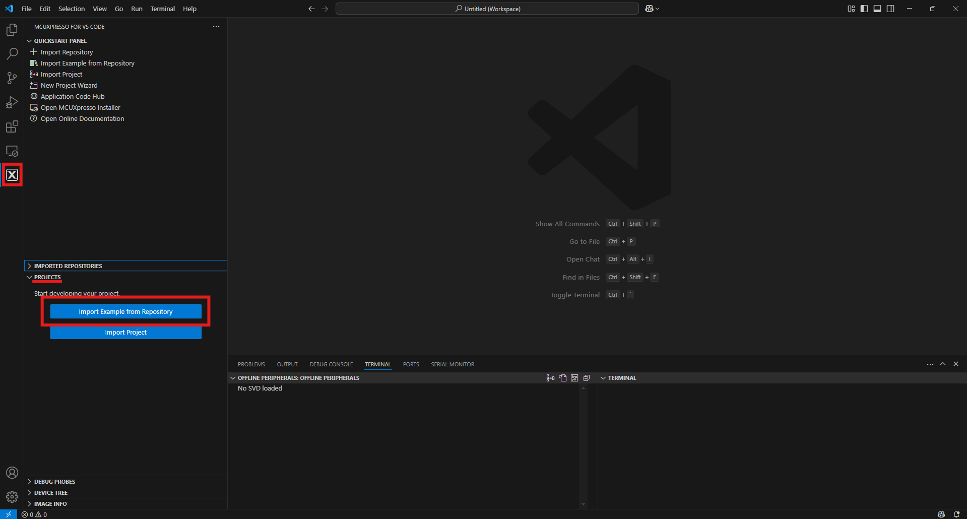
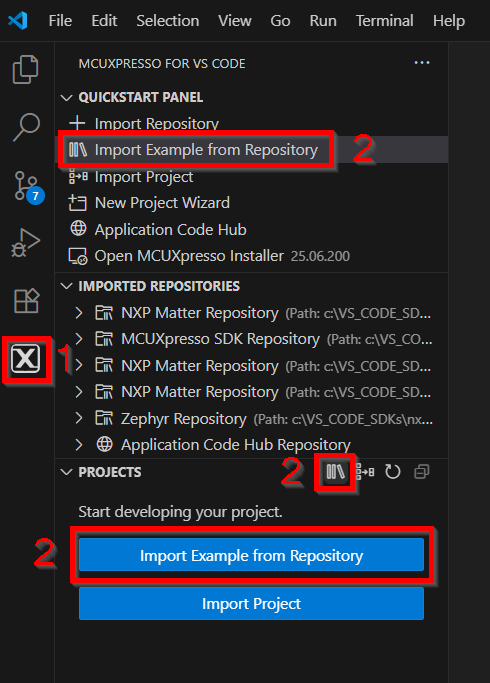
- Click on the MCUXpresso extension Icon
- Click on the “QUICKSTART PANEL” tab and then click on the "Import Repository" button, then after pressing that button, a new import window will appear on your integrated development environment (IDE)
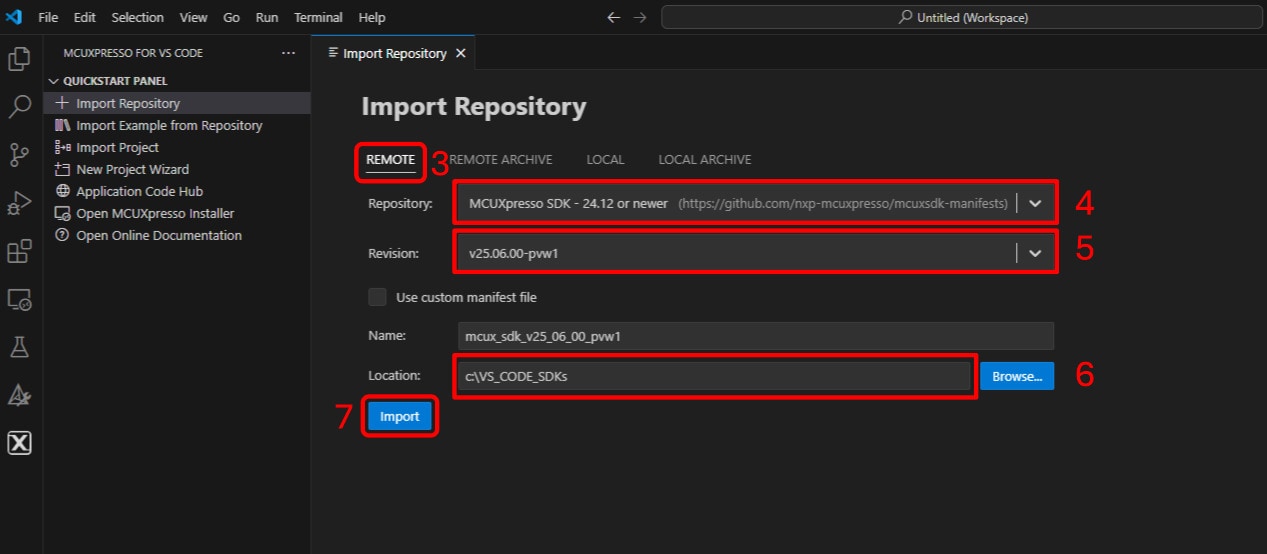
- Select the “REMOTE” option to import the SDK files
- Access the Repository options by clicking on the arrow button where you will search for "MCUXpresso SDK - 24.12" or newer
- Access the Revision options by clicking on the arrow button where you will search for version "v25.09.00" or newer
- Select a folder as the common destination to store SDKs (i.e. C:\VS_CODE_SDKs ) by entering a name for the new SDK (in this case, \mcux_sdk_v25_09_00_pvw1)
- Click Import button and wait for the installation
2.3 MCUXpresso Config Tools
The MCUXpresso Config Tool is an integrated suite of configuration tools that guides users in creating new MCUXpresso SDK projects, and also provides pin and clock tools to generate initialization C code for custom board support. It is fully integrated as a part of MCUXpresso IDE, but also as a separate tool when using a different IDE.
Click the Get MCUXpresso Config Tools button below to get the Config Tools installer.
2.4 Programming and Provisioning Tools
The MCUXpresso Secure Provisioning (SEC) Tool is a graphical user interface (GUI)-based application provided to simplify the generation and provisioning of bootable executables on NXP microcontroller unit (MCU) devices. We recommend that all users begin with the MCUXpresso Secure Provisioning (SEC) tool for trial run and mass production use. This supports secure programming and device provisioning on NXP's microcontrollers at the production stage.
After downloading the tool, find the user guide under the ‘Help’ tab. Next, follow the instructions for your board in the ‘Processor-specific workflow’ chapter.

Note: For advanced users who need a more customizable set-up, there is also the option of a command-line tool that is useful when interfacing with a custom or partner programming tool. The Secure Provisioning Secure Provisioning Software Development (SPSDK) is an open source development kit with source code that can be found on GitHub and PyPI.
3. Build and Run
The following steps will guide you through the healthcare IoT demo application using MCUXpresso for VS Code extension for the Arm® Cortex®-M33 application. The MCUXpresso extension for VS Code installation and the SDK for the MCXW-Series can be found in the Get Software section of this Getting Started guide.
3.1 Build and Flash an Application Using MCUXpresso IDE
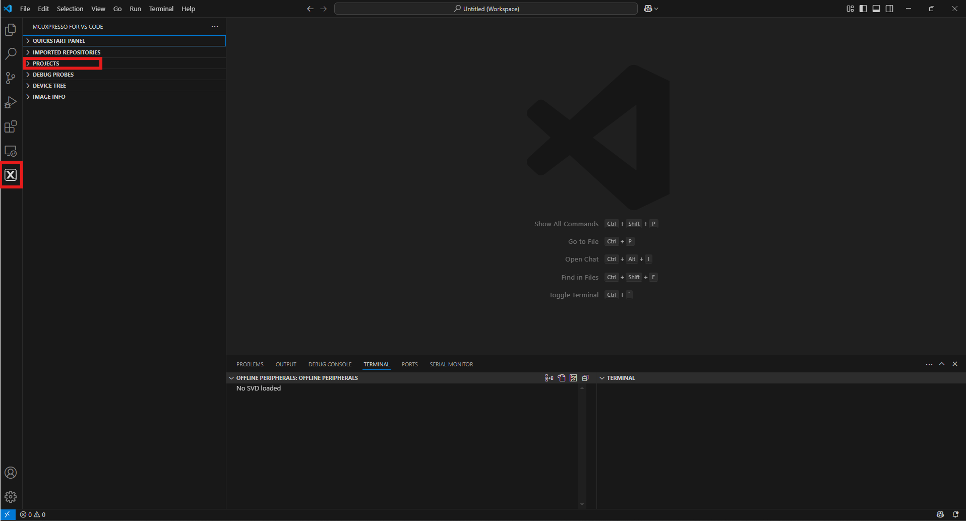
- Find the activity bar in the left-hand bar and click to open it, then go to the Explorer and open the "PROJECTS" tab
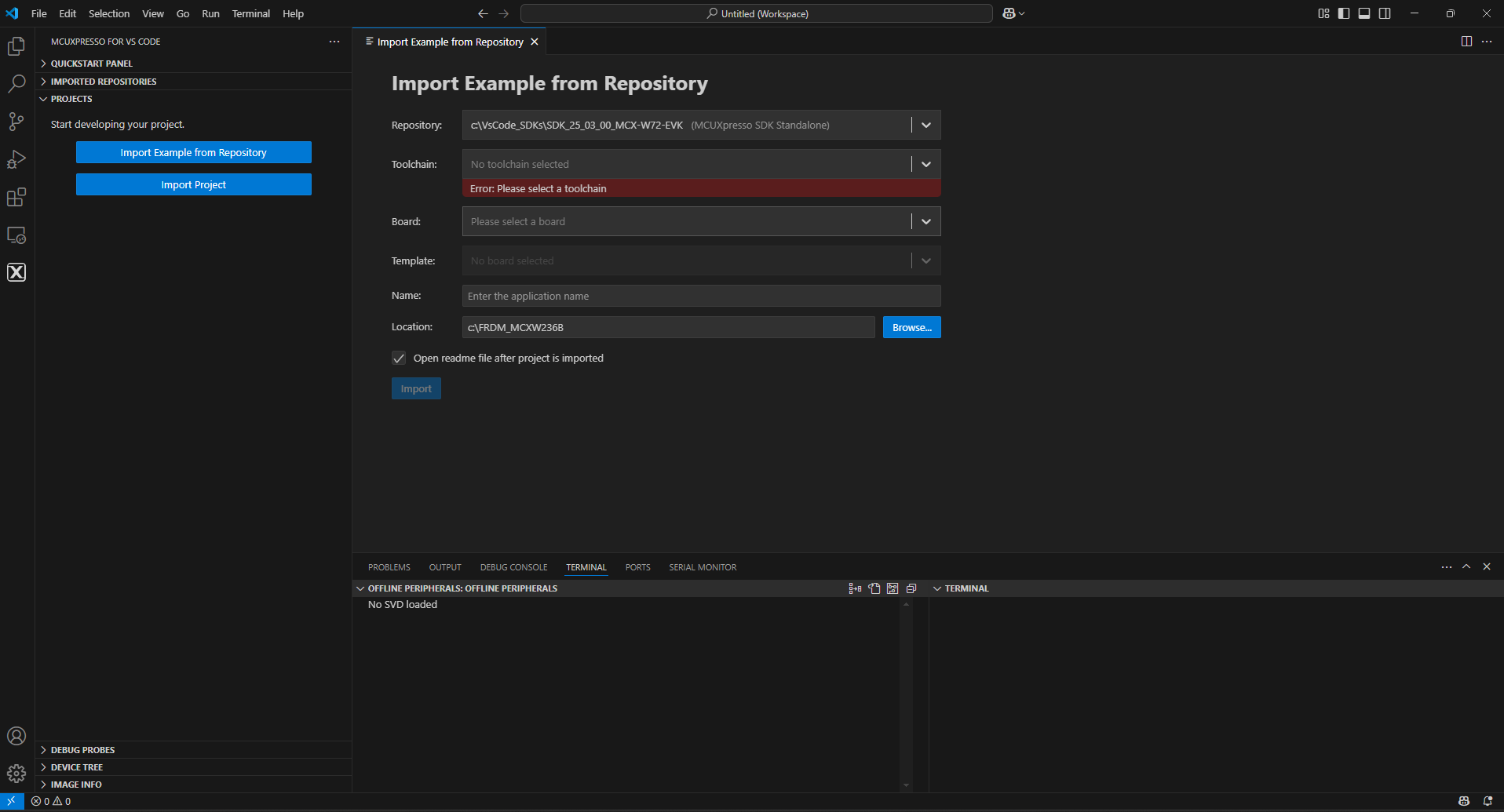
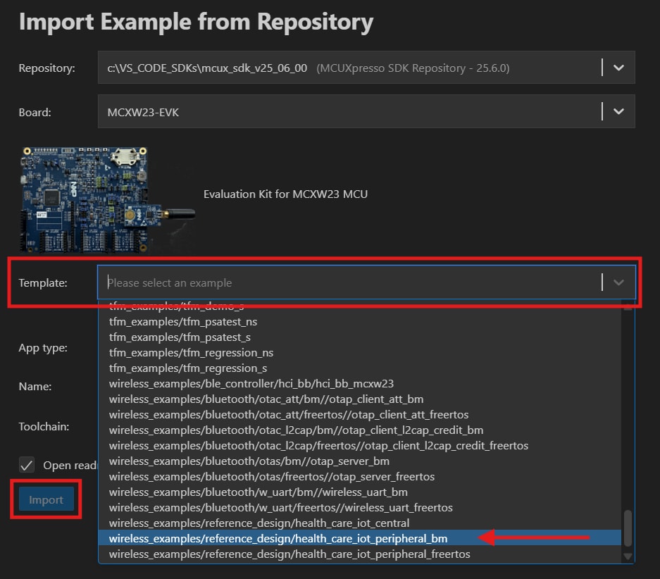
- Then click "Import Example from Repository" The following tab will open on the editor screen
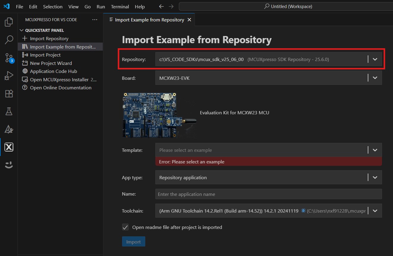
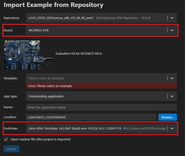
- Click the arrow button to right of the "Repository" tab to select the previously downloaded MCXW-Series board SDK and select the compatible example, then click Next
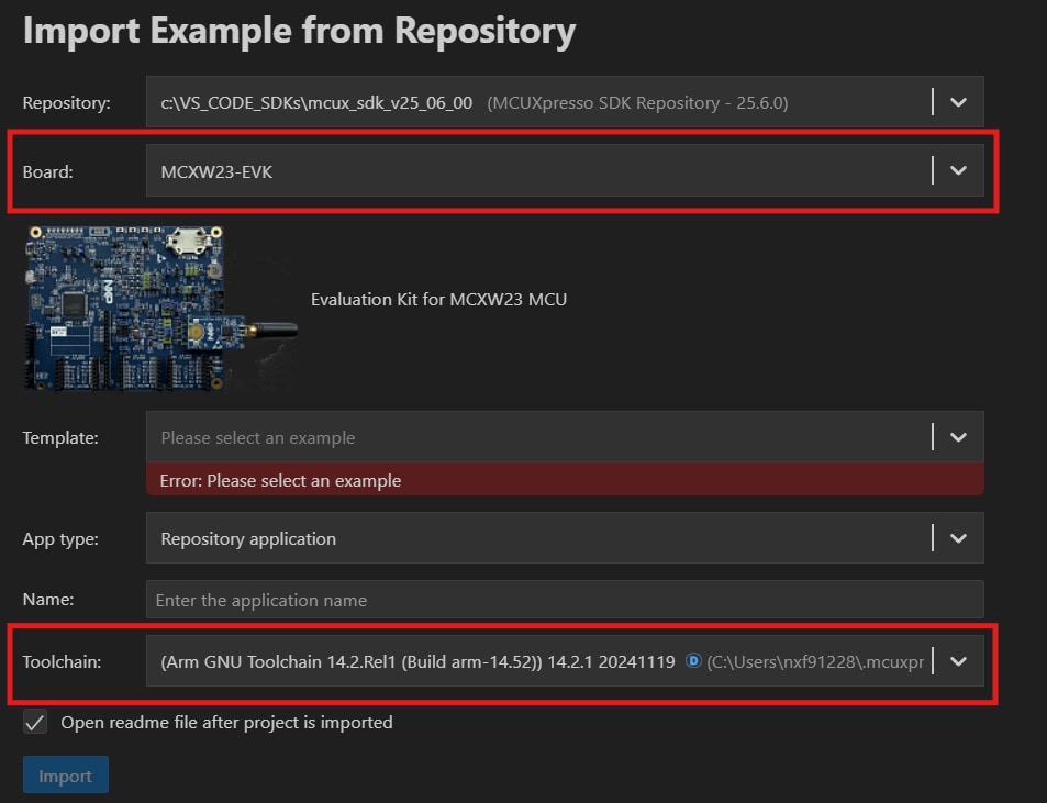
- Select the toolchain according to the SDK version, then select the appropriate board (for the process to run smoothly, the SDK and toolchain should match)
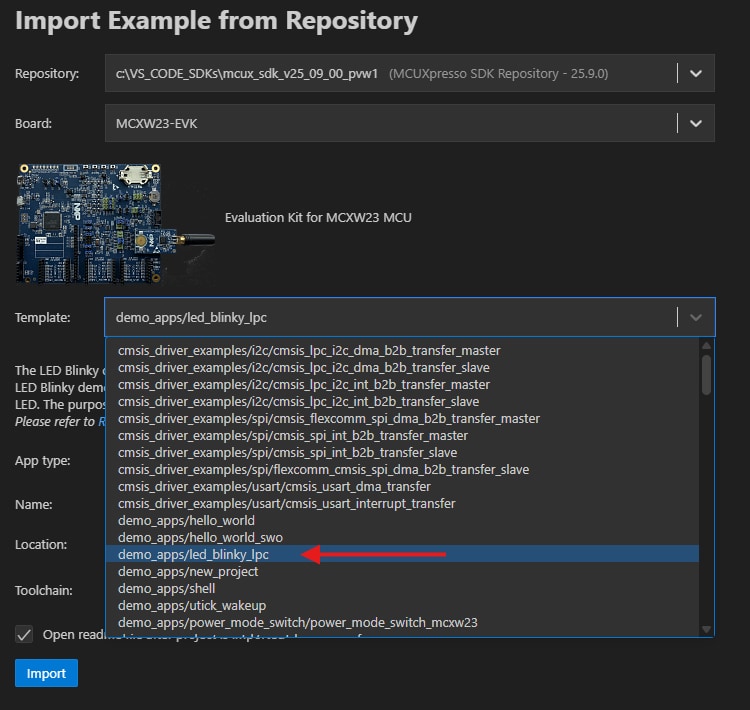
- Use the arrow button to expand the "Template" tab, and then select the "wireless_examples/reference_design/health_care_iot_peripheral_bm" to use it as a template for the project, then click "Import" button
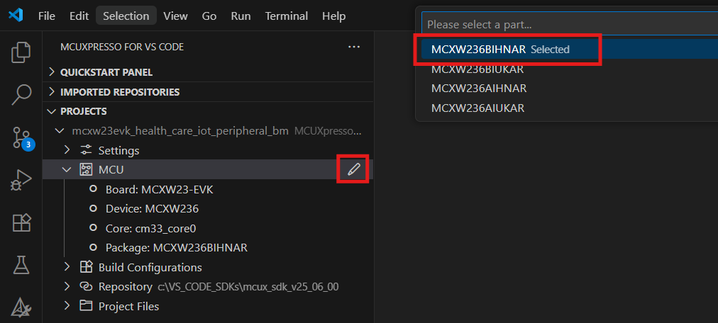
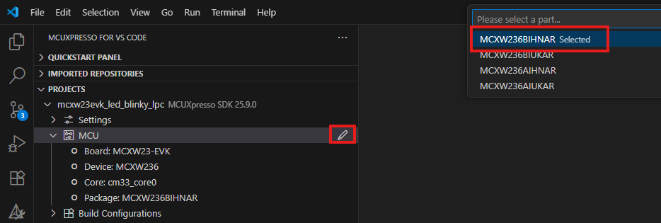
- Go to the "MCU" tab to expand the project, then search for MCXW236BIHNAR and select it (if it is not found in the MCU tab on the right side, click the change package icon button to select MCXW236BIHNAR as the project)
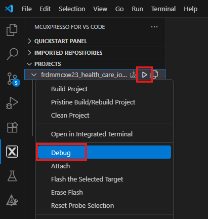
- Select the project to build it by either clicking the “build icon” in the shortcuts provided above, or by right clicking to select the "Build" option
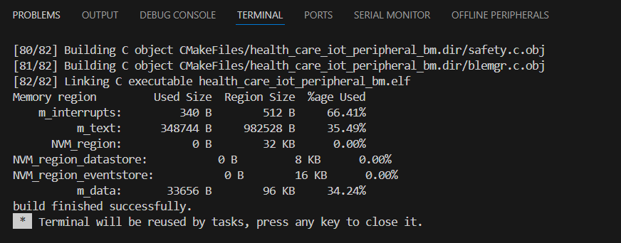
- The project should now build without any errors or warnings in the console
- Connect the board to your computer using the micro-USB to
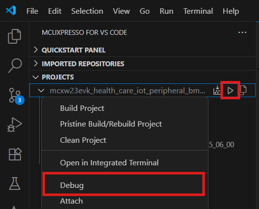
J33‘MCU-LINK’ port - Download the application to your board by either clicking the debug icon above or by right clicking to select the "Debug" option
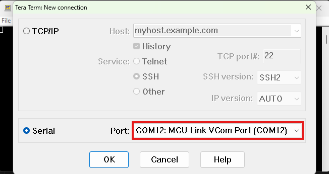
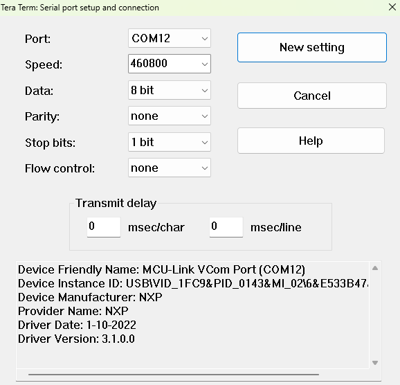
- Open up a serial terminal to see the application’s output, then in the window select the port to the MCULINK probe that corresponds to your board: “MCULink-VCOM” (set your terminal to baud rate or speed to "460800", 8-bit data, no parity and 1 stop bit and connect to that port)
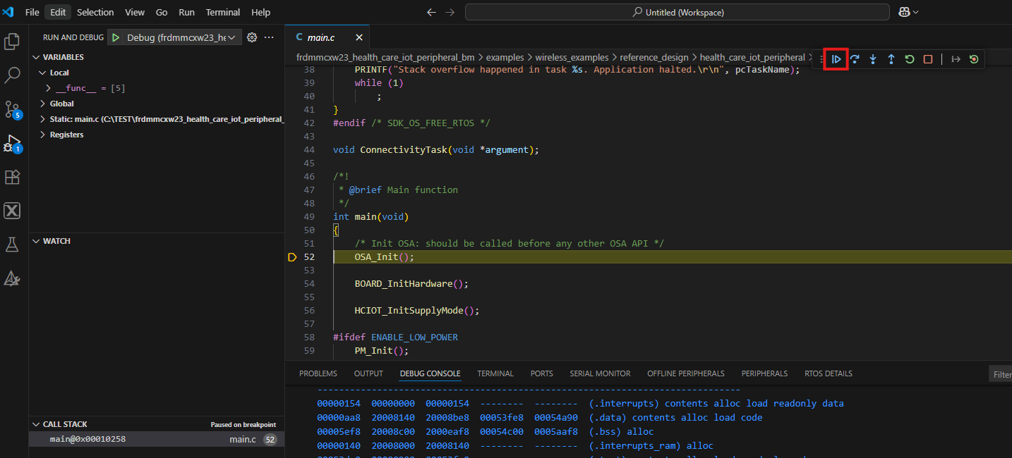
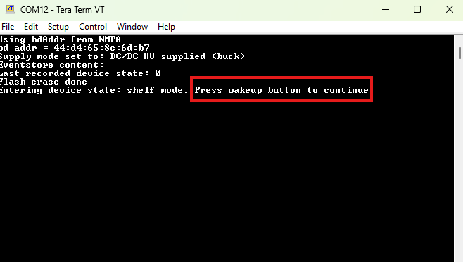
- Run the application by pressing the “run” icon (see the output printed on the terminal)
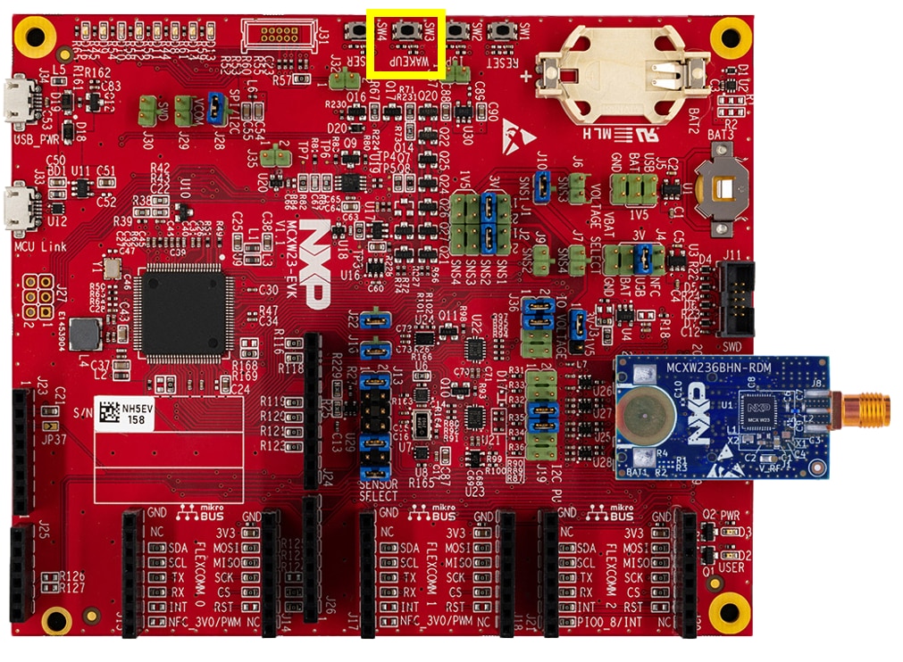
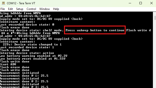
- Press the
SW3area labeled as "Wake_up" to start running the example - See the output printed on the terminal
- You can connect the demo to the IoT Toolbox app by following the steps shown in the video found in the Plug It In section of this Getting Started guide
4. Create
4.1 Clone an Example Project from MCUXpresso for VS Code
The following steps will guide you through the manipulation of the general purpose inputs/outputs (GPIOs). This example guides you in settling up GPIO that will signal to toggle an LED.
- Locate the activity bar on the left-hand menu, and click to open it
-
To import an example application, you have the following options:
- Go to the Explorer panel, open the Project tab and click "Import Example Application from Repository"
- Click the import repository icon
- Go to the Quickstart panel and click the "Import Example from Repository" button
- Click and select the Repository for the MCXW23-EVK board and select the corresponding toolchain that matches the SDK version
- Use the arrow button on the right to expand the template category, then search for "demo_apps/led_blinky_lpc" and click the line of the same name, then click "Import"
- Go to the "MCU" tab to expand the "mcxw23evk_led_blinky_lpc" project by selecting MCXW236BIHNAR (if it is not found in the MCU tab on the right side, click the change package icon button to select MCXW236BIHNAR as the project)
- Select the “mcxw23evk_led_blinky_lpc” project from the list, then compile and run the demo as described in the previous section
- You should now see the RED LED changing back and forth
- Terminate the debug session
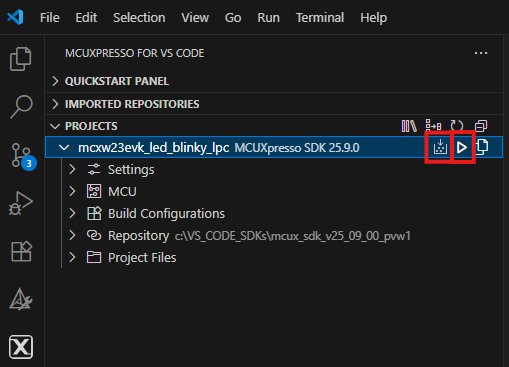
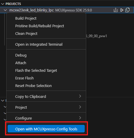
4.2 Use MCUXpresso IDE Pins Tools
- Open the pins tool by right clicking the project, then selecting the “Open with MCUXpressoConfigTools” button
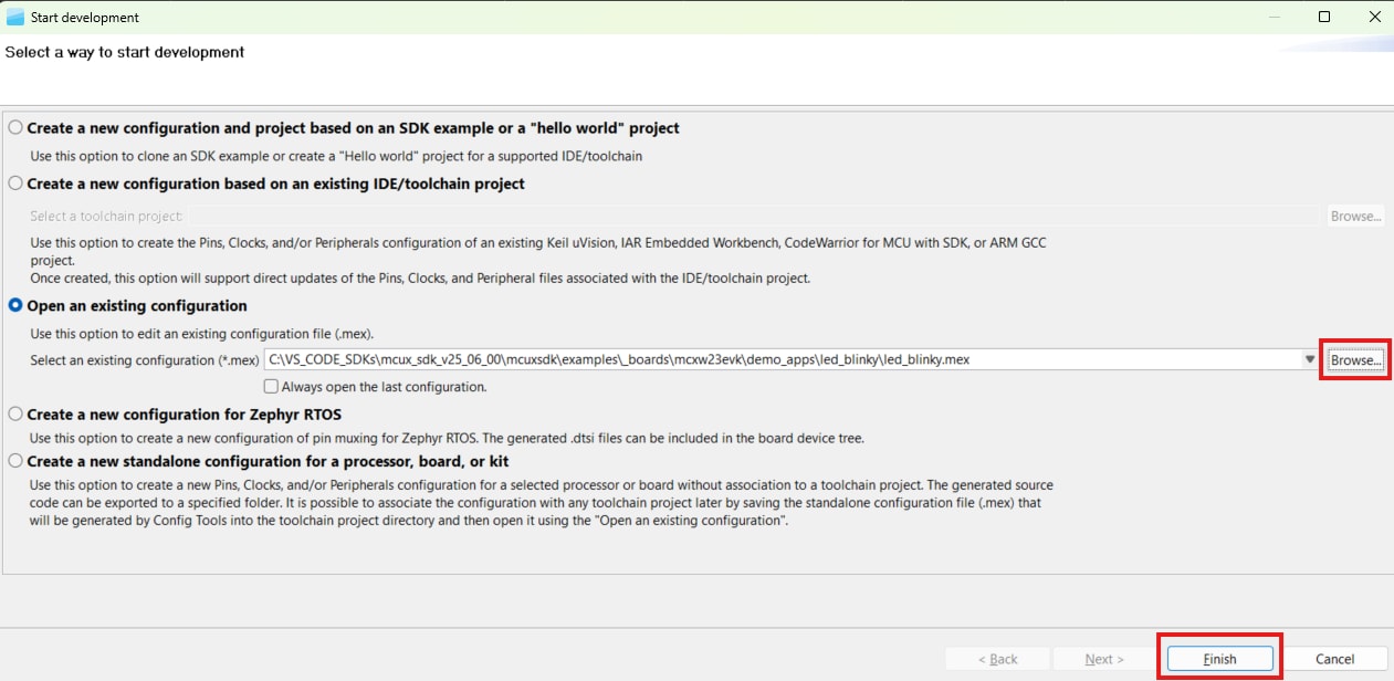
- The pins tool should now display the "Start developing" window where you will search for the .mex file of the project and select it (if this file is included in your project you can search for it in the path: /mcux/mcuxsdk\examples\_boards\mcxw23evk\\) Referring to the image provided, navigate to your SDK path, select the .mex file for your project (this file contains the configuration settings), then click "Next" and then "Finish" to load the configuration
4.3 Use MCUXpresso Config Tools
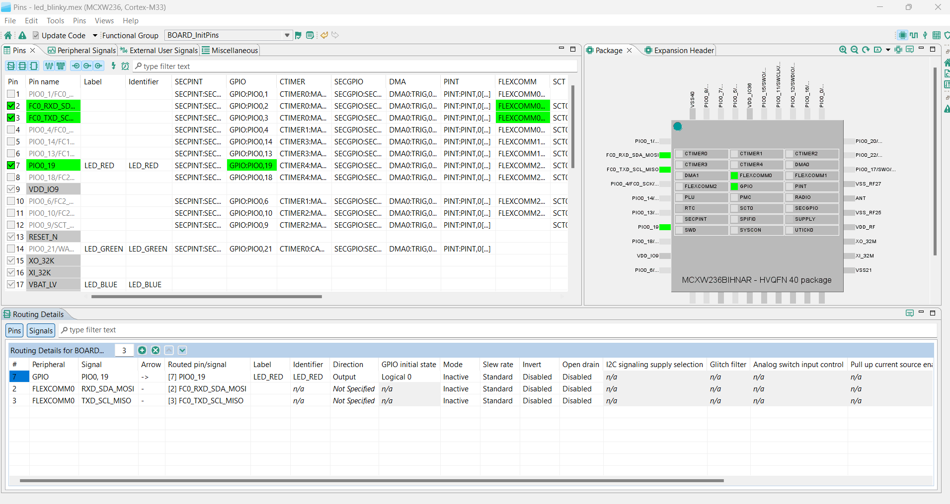
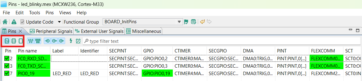
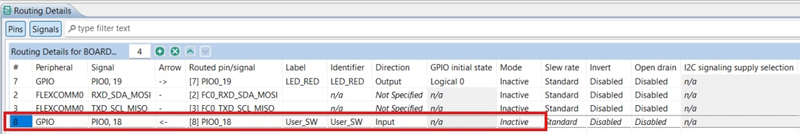
- You will use MCUXpresso Config tools to edit the pin configuration for this project, so in the "Pins" view, deselect “Show dedicated pins” and “Show no routed pins” checkboxes to see only the routed pins (routed pins will have a check in a green box next to the pin name and the functions selected for each routed pin are highlighted in green)
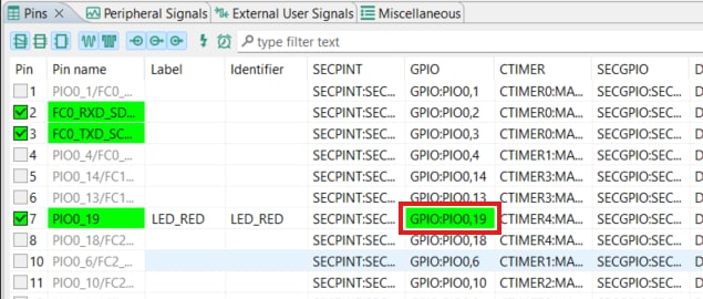
- In the current configuration, PIO0_19 is routed as the output of the GPIO to toggle the LED and here you will add the pin configuration to enable the
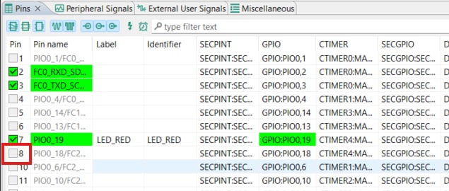
SW4button - Select “Show no routed pins” to see the other options, then enable the
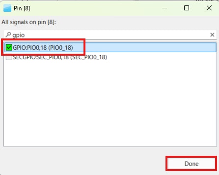
SW4button by searching for PIO0_18 and clicking the checkbox under the PIN column - After clicking the checkbox, this window will appear, then type on the searchbox "gpio," select "GPIO:PIO0,18" and click done
- Check the pin configuration to be set as an output in the “Routing Details” window
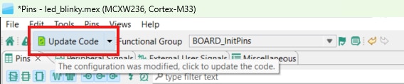
- Now you will implement these changes to the project by exporting the new updated pin_mux.c and pin_mux.h files that are generated by the Pins tool and click "Update Code" in the menu bar
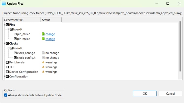
- Now, save your file to proceed to export the new configuration by pressing either CTRL+S or by clicking the File tab and click "Save"
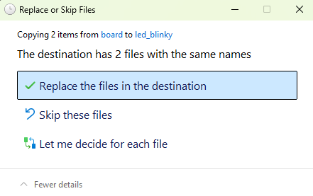
- The screen that pops up will show which files are changing (you can click “diff” to see the difference between the current file and the new file generated by the Pins tool)
- Click “OK” to overwrite the new files into your project
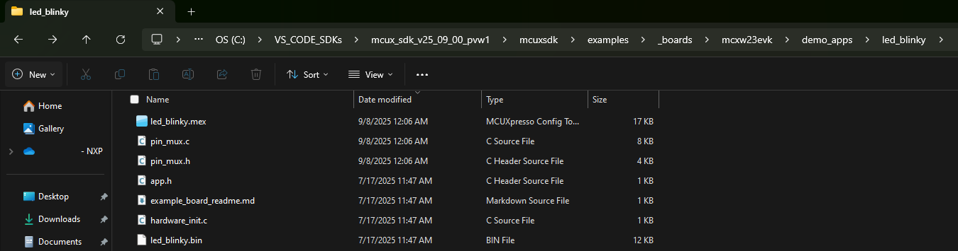
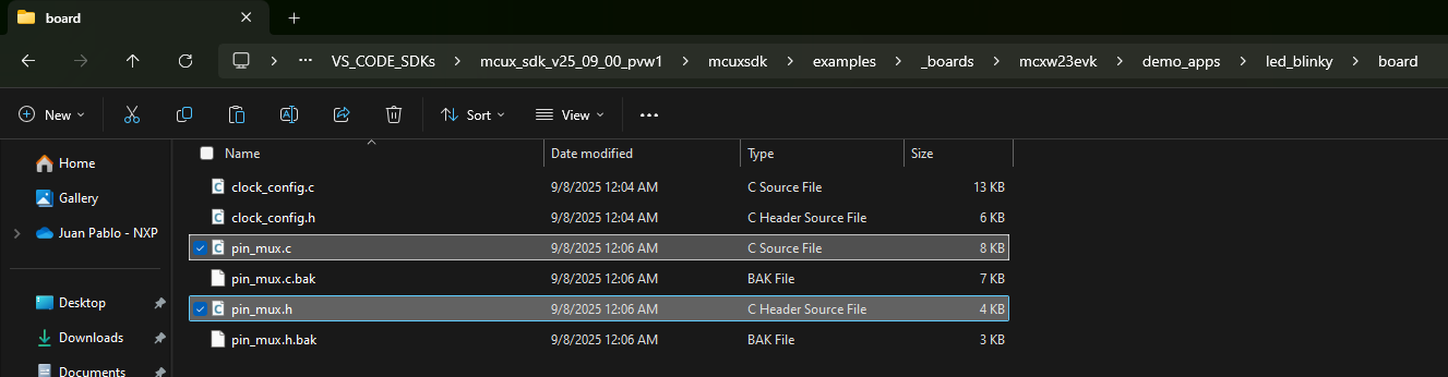
- Next, you will replace the new generated files from the tool created inside a new folder called "board" (located in your examples path as shown in previous steps) by copying the files from this folder into the original example folder which will change the project files to the new version
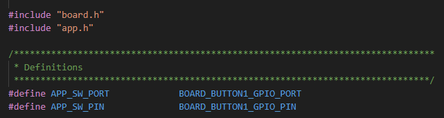
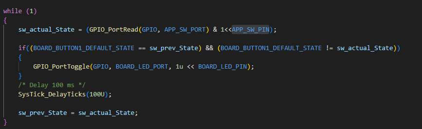
- To add additional code to the example, open the led_blinky.c file and add the following macros to control and read the
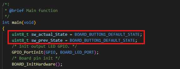
SW4GPIO pin - Add the two variables to store the sw state values as those will be used later to control the LED state
- In the last while loop, add these modifications
- Build and download the project as shown in the previous section
- Run the application (now every time you press the
SW4the LED will toggle from its current state) - Terminate the debug session
5. MCUXpresso Developer Experience
Check out each of the following sections to learn about the flexible protoyping and development ecosystem. The video below will provide you an introduction to the FRDM platform, the full-featured EVK and the compatible shields for extended capabilities. In addition we will walk you through our Application Code Hub (ACH) portal where we provide numerous application examples through NXP's Github.
5.1 FRDM Platform, Full Feature EVK and Shields
For quick prototyping platforms, we offer both the low-cost FRDM platform and the full-featured EVK.
FRDM development boards come with standard form factor and headers, easy access to MCU I/Os, on-board MCU-Link debugger and a USB-C cable. Our full-featured EVKs include extended I/O and interface access, extendibility with WiFi and additional MCU-Link features. There are also many compatible Click Boards and/or Arduino shields. For devices supported by an Open Cortex Microcontroller Software Interface Standard (CMSIS) Pack, example projects may be available on ACH. If not, many are still easy to use via serial interfaces like inter-integrated circuit (I²C), serial peripheral interface (SPI) and universal asynchronous receiver/transmitter (UART)—drivers and example code for these are included in the MCUXpresso SDK.
5.2 Application Code Hub
The ACH further enhances our MCUXpresso Developer Experience by giving you an interactive dashboard to quickly locate software. Visit the ACH today to start exploring or discover additional details and benefits of the new interactive Application Code Hub.
Software in the ACH is located in NXP’s GitHub repository so it can be easily accessed and cloned from that location directly.
5.3 Demo Walkthrough
The following demo walks you through importing a project from ACH using a system based on the FRDM platform including a motor control shield and a low cost LCD. Although your evaluation board may differ from this system, the following steps can be followed for all supported platforms.
Design Resources
Support
Support
Connect with other engineers and get expert advice on designing with the MCXW236BHN-RDM on one of our community sites.