FRDM-K22F Dev Board Quick Starts
Contents of this document
-
Out of the Box
-
Get Hardware
-
Install Software
-
Configure Hardware
Sign in to save your progress. Don't have an account? Create one.
Purchase your Board for FXLS8974CF 3-Axis IoT Accelerometer
1. Out of the Box
Sensor evaluation boards provide a wide spectrum of enablement hardware for quick sensor evaluation and development. It includes a demonstration kit, shield development board and breakout board for motion and pressure sensors targeted toward IoT, Industrial, Medical applications.
This page will guide you through the process of setting up and using the FRDM-K22F-A8974 board.
1.1 Kit Contents and Packing List
The FRDM-K22F-A8974 contents include:
- FRDM-STBI-A8974: FXLS8974CF sensor shield board
- USB cable
- FRDM-K22F MCU board
- Quick Start Guide
2. Get Hardware
2.1 Board Features
- Sensor evaluation board for FXLS8974CF is offered as sensor kit with FRDM-K22F
- Enables quick sensor evaluation and helps accelerate quick prototyping and development using NXP sensors
- Compatible with Arduino and most NXP FRDM development boards
- Supports I²C and SPI communication interface with host MCU
- Supports hardware configurability to switch between accelerometer mode (normal versus motion detect) and I²C/SPI interface mode
- Has multiple test points on the board
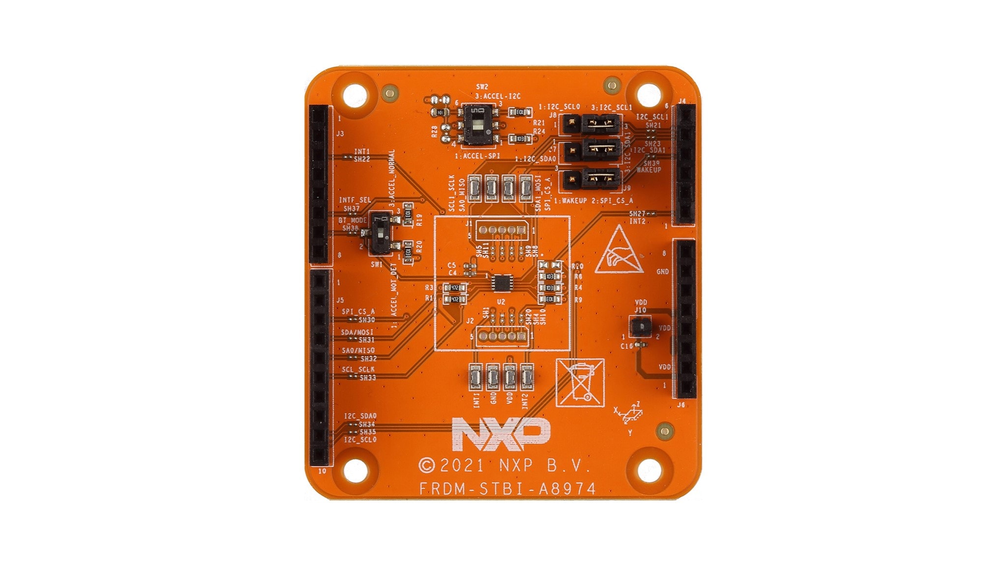
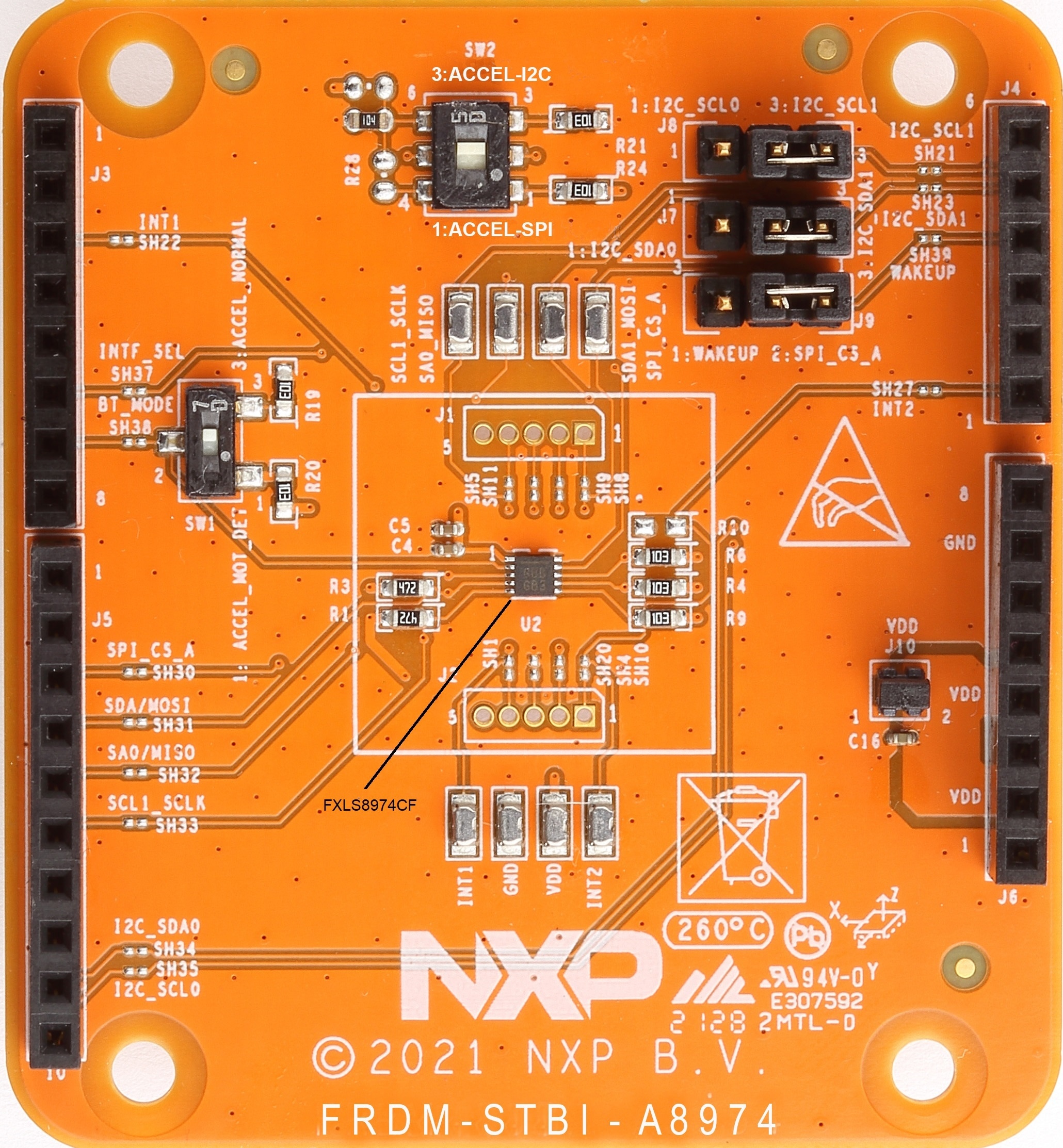
2.2 Board Description
The FRDM-STBI-A8974 is a sensor add-on/companion shield board for FXLS8974CF 3-axis low-power motion wake accelerometer.
FRDM-STBI-A8974 sensor shield board is kitted with a FRDM MCU (FRDM-K22F) board to enable quick customer evaluation of FXLS8974CF using sensor toolbox enablement software and tools.
2.3 Kit Featured Components
Overview of the FRDM-K22F-A8974 sensor toolbox development board.
3. Install Software
3.1 Install Software
Follow the getting started instructions provided for the following sensors development software tools to jump-start your evaluation or development using FRDM-STBI-A8974 sensor shield board combined with the FRDM-K22F:
4. Configure Hardware
4.1 Using FRDM-K22F-A8974 Evaluation Board
- Check and confirm FRDM-K22F-A8974 Sensor shield board settings as described below:
- To select I²C digital interface, connect pins 2-3 of
SW2on FRDM-STBI-A8974 shield board - To select SPI digital interface, connect pins 1-2 of
SW2on FRDM-STBI-A8974 shield board - Connect pins 2-3 of
SW1to select default accelerometer operating mode i.e. "ACCEL NORMAL" mode - Connect FRDM-K22F-A8974 Sensor shield board to FRDM-K22F MCU board using Arduino I/O headers
- Connect the sensor demonstration kit (FRDM-STBI-A8974 shield board kitted with FRDM-K22F) to the training PC via the USB cable between the OpenSDA USB port on the board and the USB connector on the PC
- For a smooth ‘out-of-box’ experience with sensor development software tools, make sure that the latest version of the default OpenSDA bootloader and firmware application is on the FRDM-K22F. This allows debugging, flash programming and serial communication over a USB cable. Obtain the latest OpenSDA drivers for FRDM boards available at OpenSDA update to the FRDM boards
Design Resources
Board Information
Additional Resources
In addition to our Sensor ToolBox Development Board for FXLS8974CF 3-Axis IoT Accelerometer page, you may also want to visit:
Product Pages
- FXLS8974CF: ±2g/±4g/±8g/±16g, Low Power 12-Bit Digital IoT
- FRDM-K22F: NXP FRDM Development Platform for Kinetis® K22 MCUs
Application Pages
Support
Forums
Go to Support or connect with other engineers and get expert advice on our community site.