Getting Started with the FRDMGD3160HBIEVM
Contents of this document
-
Get started
-
Get to Know the Hardware
-
Configure Hardware
-
Install Software
Sign in to save your progress. Don't have an account? Create one.
Purchase your FRDMGD3160HBIEVM | GD3160 Half-Bridge Evaluation Kit
1. Get started
The NXP analog product development boards provide an easy-to-use platform for evaluating NXP products. The boards support a range of analog, mixed-signal and power solutions. They incorporate monolithic integrated circuits and system-in-package devices that use proven high-volume technology. NXP products offer longer battery life, a smaller form factor, reduced component counts, lower cost and improved performance in powering state-of-the-art systems.
This page will guide you through the process of setting up and using the FRDMGD3160HBIEVM board.
1.1 Kit Contents/packing List
The FRDMGD3160HBIEVM contents include:
- Assembled and tested FRDMGD3160HBIEVM board in an anti-static bag
- 3.3 V to 5.0 V translator board (KITGD3160TREVB) connected to FRDM-KL25Z
- USB cable, type A male/type mini B male, 3 ft
- Quick Start Guide
1.2 Additional Hardware
In addition to the kit contents, the following hardware is necessary or beneficial when working with this kit.
- Compatible HybridPACK Drive IGBT or SiC MOSFET module
- DC link capacitor compatible with the HybridPACK Drive module
- 1.27 mm jumpers for configuration (included with kit)
- 30 μH to 50 μH, high current air core inductor for double pulse testing
- HV power supply with protection shield and hearing protection
- 25 V, 1.0 A DC power supply
- 500 MHz 2.5 GS/s 4-channel oscilloscope
- Rogowski coil, PEM Model CWT Mini HF60R or CTW MiniHF30 (smaller diameter)
- Isolated high-voltage probe (CAL Test Electric CT2593-1, LeCroy AP030)
- Digital voltmeter
1.3 Windows PC Workstation
This evaluation board requires a Windows PC workstation. Meeting these minimum specifications should produce great results when working with this evaluation board.
- Windows 7 or higher operating system
2. Get to Know the Hardware
2.1 Board Features
- Capability to connect to HybridPACK Drive module for half-bridge evaluations
- Negative VEE gate low drive level (-3.9 V DC)
- VCCREG regulated high gate drive level (+15 V DC)
- Jumper configurable for disabling dead time fault protection when short-circuit testing
- Easy access power, ground and signal test points
- Easy to install and use FlexGUI for interfacing via SPI through PC; software includes double pulse and short-circuit testing capability
- DC link bus voltage monitor on low-side driver via AMUXIN and AOUT
- Negative temperature coefficient (NTC) connection and configurable for monitoring module temperature
2.2 Board Description
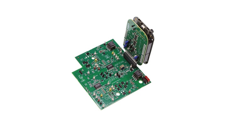
The FRDMGD3160HBIEVM is a half-bridge evaluation board populated with two GD3160 single channel IGBT or SiC gate drive devices. The board supports connection to an FRDM-KL25Z microcontroller for SPI communication configuration programming and monitoring. The board includes DESAT circuitry for short-circuit detection and implementation of GD3160 shutdown protection capabilities.
The evaluation board is designed to connect to a HybridPACK drive module for evaluation of the GD3160 performance and capabilities.
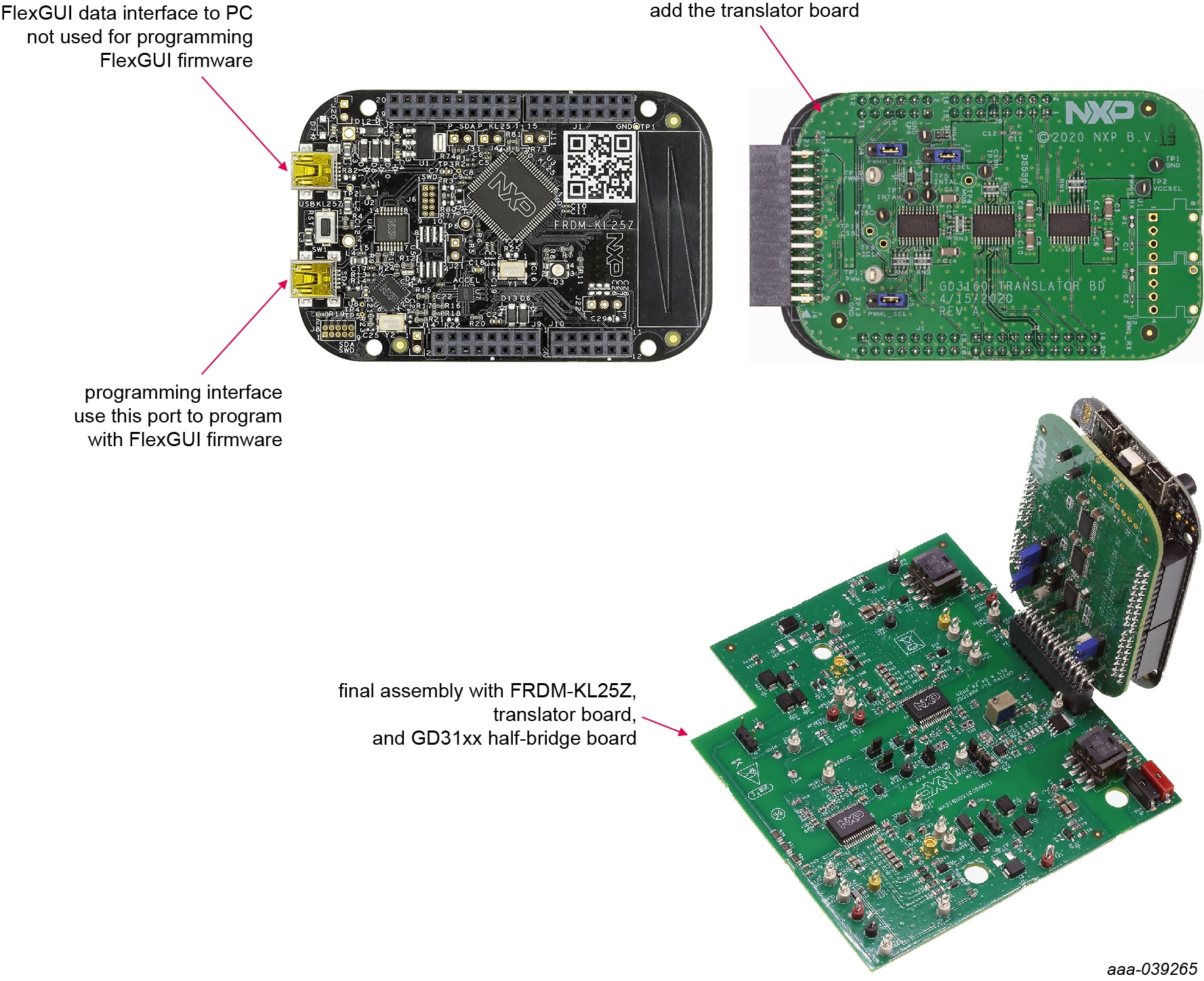
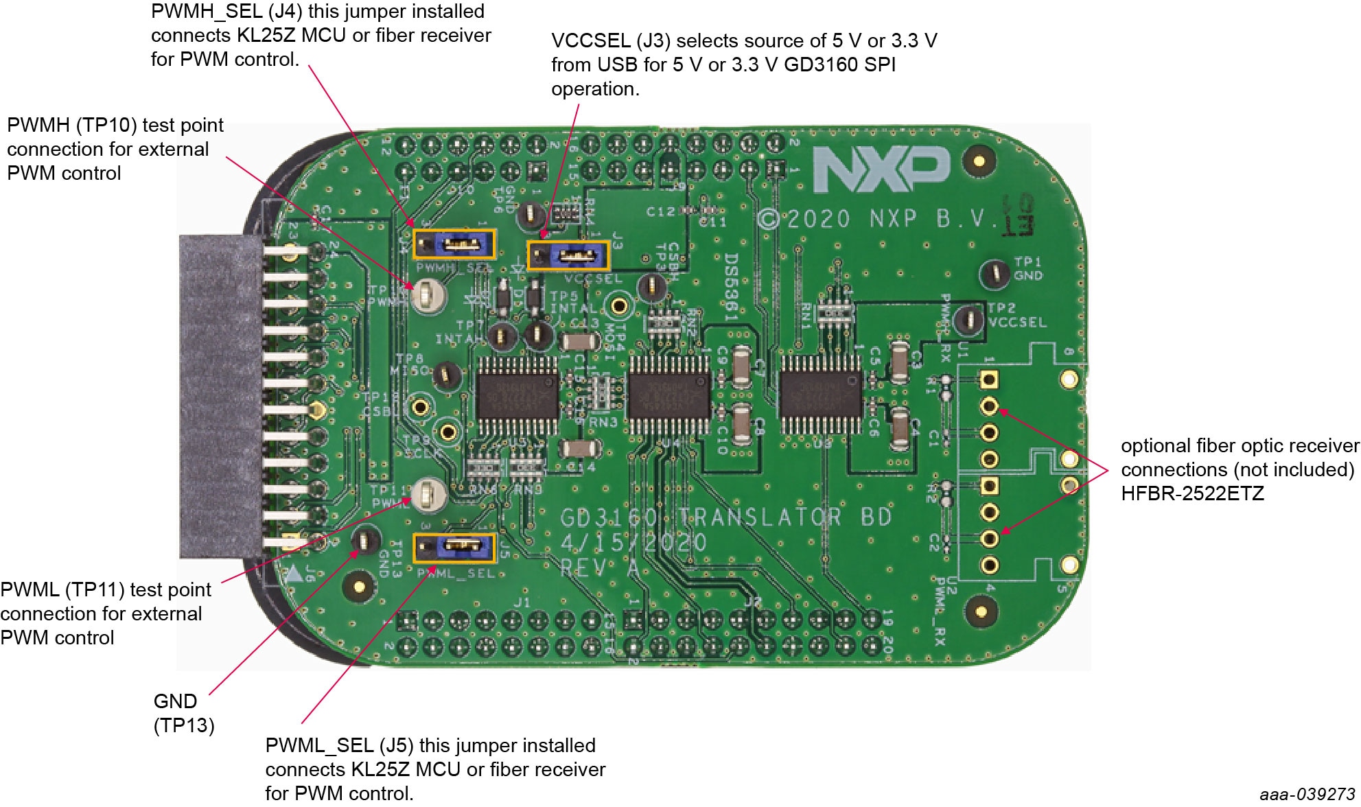
2.3 3.3 V to 5.0 V Translator Board
KITGD3160TREVB translator enables level shifting of signals from MCU 3.3 V to 5.0 V SPI communication.
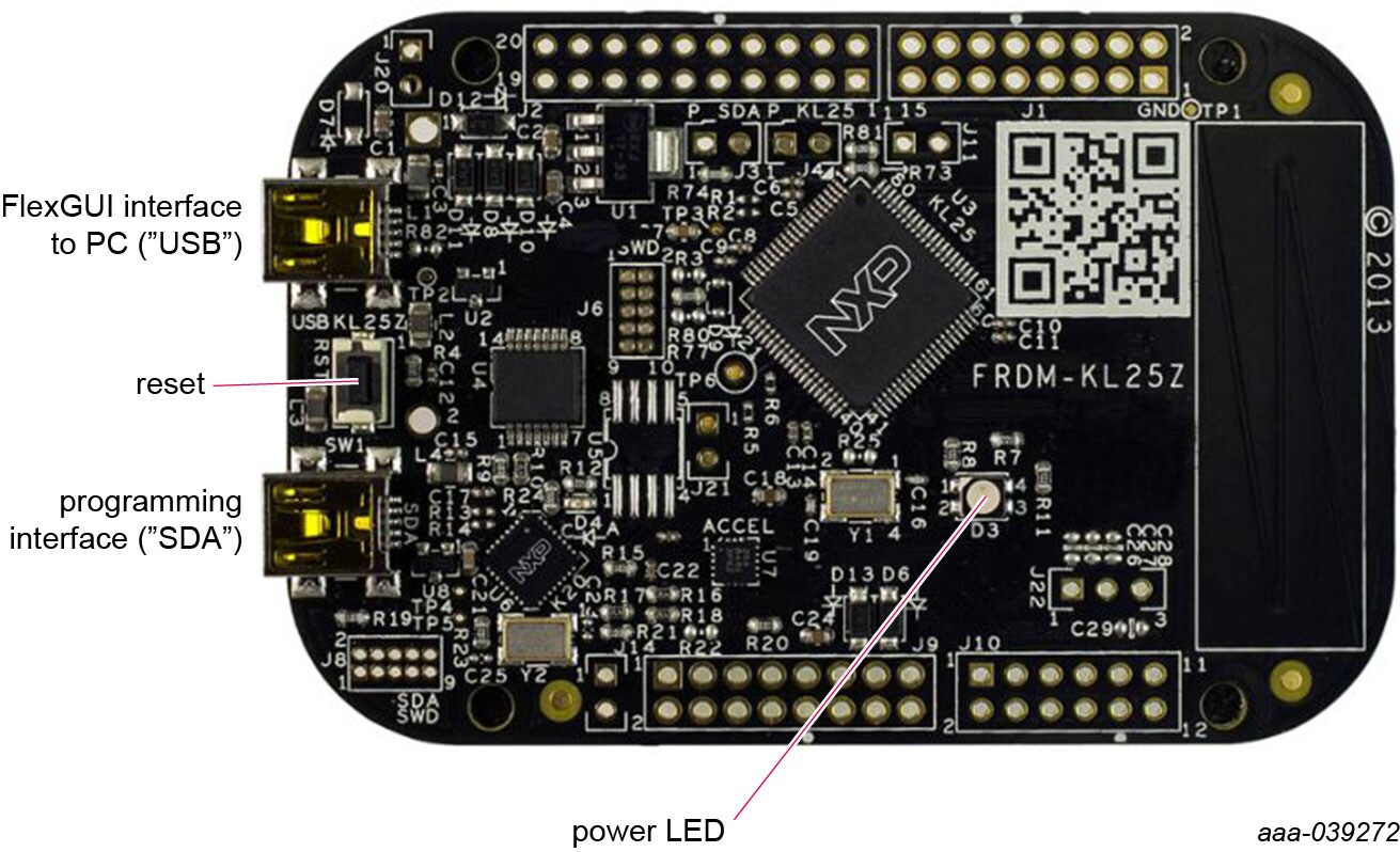
2.4 Kinetis KL25Z Freedom Board
The Freedom KL25Z is an ultra-low-cost development platform for Kinetis® L Series KL1x (KL14/15) and KL2x (KL24/25) MCUs built on Arm® Cortex®-M0+ processor.
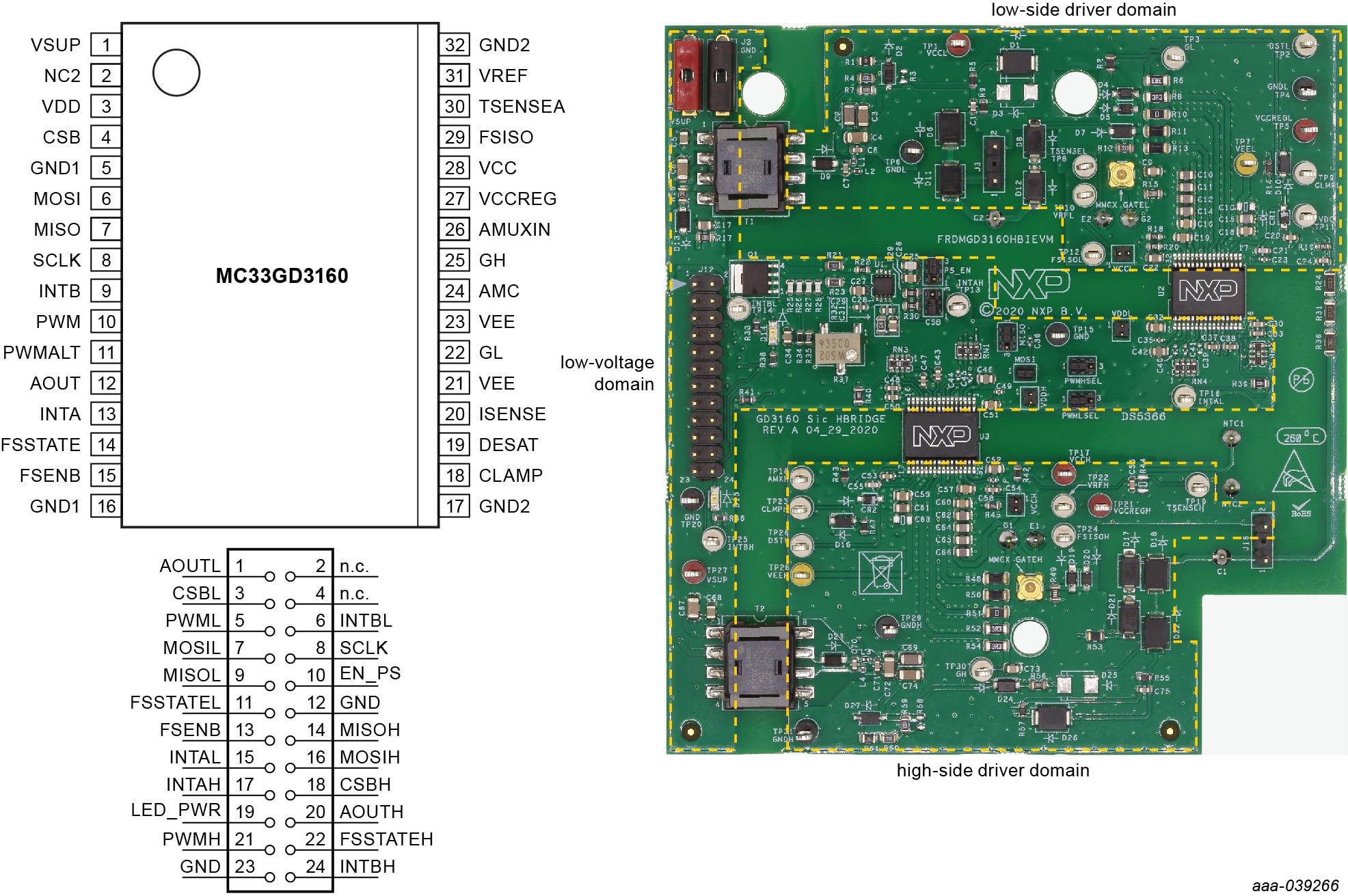
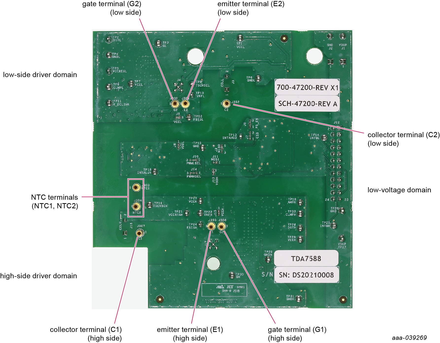
2.5 Board Components
Overview of the FRDMGD3160HBIEVM half-bridge evaluation board.
3. Configure Hardware
3.1 Configure Hardware
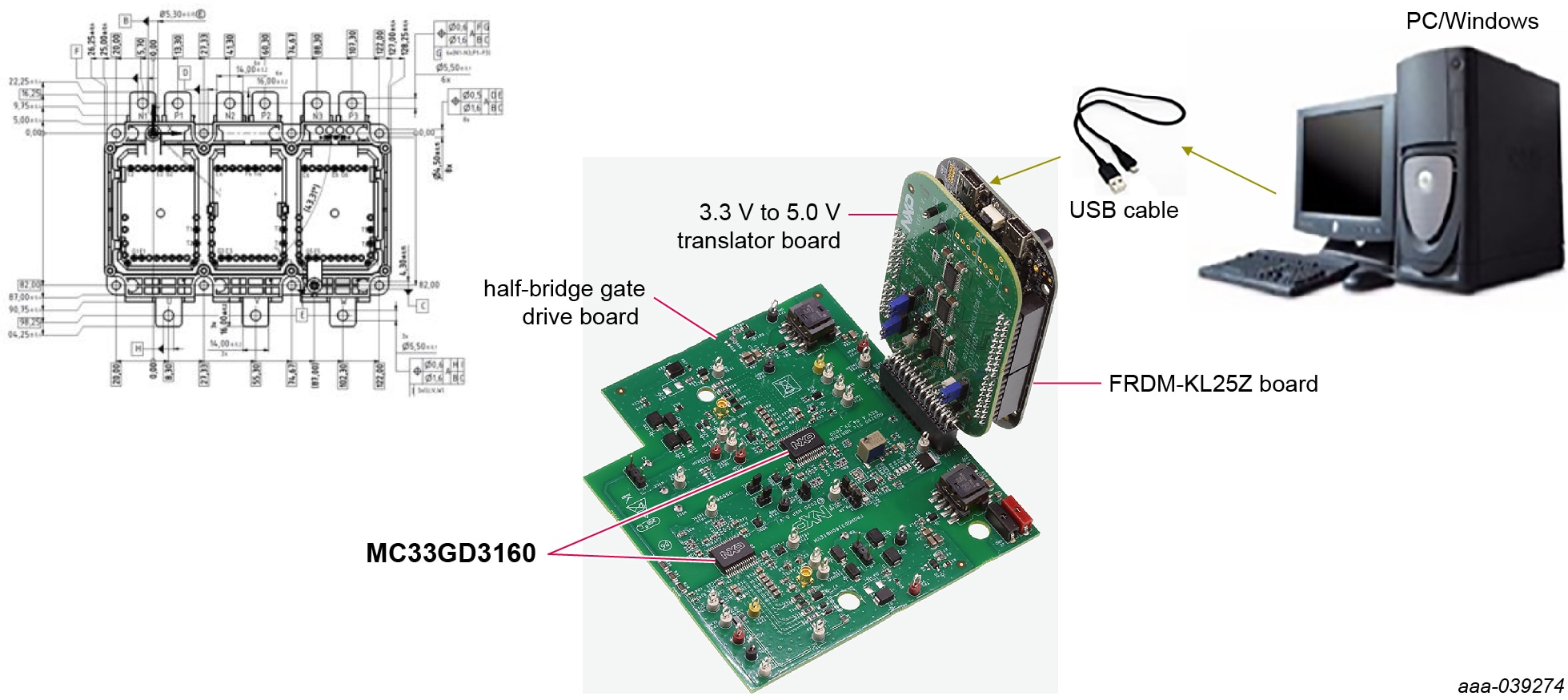
The following figure presents a typical hardware configuration.
FRDMGD3160HBIEVM is connected to compatible SiC MOSFET HybridPACK drive module with a DC link capacitor as shown in Figure 11. Double pulse and short-circuit testing can be conducted utilizing Windows-based PC with FlexGUI software.
Suggested equipment needed for test:
- Rogowski coil high-current probe
- High-voltage differential voltage probe
- High sample rate digital oscilloscope with probes
- DC link capacitor compatible with HybridPACK drive module
- IGBT or SiC MOSFET HybridPACK drive module
- Windows-based PC
- High-voltage DC power supply for DC link voltage
- Low-voltage DC power supply for VSUP - +12 V DC gate drive board low-voltage domain
- Voltmeter for monitoring high-voltage DC link supply
- Load coil for double pulse and short-circuit testing
4. Install Software
Software for FRDMGD3160HBIEVM is distributed with the FlexGUI tool (available on NXP.com). Necessary firmware comes pre-installed on the FRDM-KL25Z with the kit.
Even if the user intends to test with other software or PWM, it is recommended to install this software as a backup or to help debugging.
4.1 Installing FlexGUI on Your Computer
The latest version of FlexGUI supports the GD3100 and GD3160. It is designed to run on any Windows 10 or Windows 8 based operating system. To install the software, do the following:
- Go to FlexGUI and click Download.
- When the FlexGUI software page appears, click Download and select the version associated with your PC operating system.
-
FlexGUI wizard creates a shortcut and an NXP FlexGUI icon appears on the desktop. By default, the FlexGUI executable file is installed at
C:\flexgui-app-des-gd31xx.exe. Installing the device drivers overwrites any previous FlexGUI installation and replaces it with a current version containing the GD31xx drivers. However, configuration files (.spi) from the previous version remain intact.
4.2 Configuring the FRDM-KL25Z Microcode
By default, the FRDM-KL25Z delivered with this kit is preprogrammed with the current and most up-to-date firmware available for the kit.
A way to check quickly that the microcode is programmed and the board is functioning properly, is to plug the KL25Z into the computer, open FlexGUI and verify that the software version at the bottom is 6.4 or later.
If a loss of functionality following a board reset, reprogramming or a corrupted data issue, the microcode may be rewritten per the following steps:
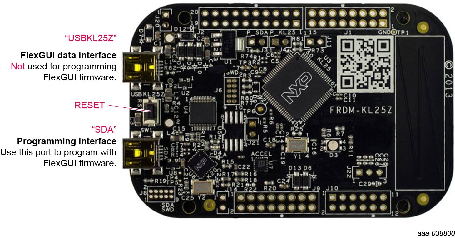
- To clear the memory and place the board in boot loader mode, hold down the reset button while plugging a USB cable into the OpenSDA USB port
- Verify that the board appears as a BOOTLOADER device and continue with step 3. If the board appears as KL25Z, you may go to step 6
- Download the Firmware Apps
.ziparchive from the PEmicro OpenSDA webpage (OpenSDA ). Validate your email address to access the files - Find the most recent
MDS-DEBUG-FRDM-KL25Z_Pemicro_v118.SDAand copy/drag-and-drop into the BOOTLOADER device - Reboot the board by unplugging and replugging the connection to the OpenSDA port. Verify now that the device appears as a KL25Z device to continue
-
Locate the most recent KL25Z firmware; which is distributed as part of the FlexGUI package.
- From the FlexGUI install directory, which is located in the
flexgui-app-des-gd31xx\binfolder and is named in the form “flexgui-fw-KL25Z_usb_hid_gd31xxC_v0.3.0.bin” - This .bin file is a product/family-specific configuration file for FRDM-KL25Z containing the pin definitions, SPI/PWM generation code and pin mapping assignments necessary to interface with the translator board as part of FRDMGD3160HBIEVM
- From the FlexGUI install directory, which is located in the
-
With the KL25Z still plugged through the OpenSDA port, copy/drag-and-drop the .bin file into the KL25Z device memory. Once done, disconnect the USB and plug into the other USB port, labeled KL25Z
- The device may not appear as a distinct device to the computer while connected through the KL25Z USB port, this is normal
-
The FRDM-KL25Z board is now fully set up to work with FRDMGD3160HBIEVM and the FlexGUI
- There is no software stored or present on either the driver or translator boards, only on the FRDM-KL25Z MCU board
All uploaded firmware is stored in non-volatile memory until the reset button is hit on the FRDM-KL25Z. There is no need to repeat this process upon every power up, and there is no loss of data associated with a single unplug event.
4.3 Ready to Use
Start embedded application development.
Design Resources
Additional Resources
Product Summary Page
The product summary page for GD3160 is at GD3160.
Tool Summary Page
The tool summary page for FRDMGD3160HBIEVM board is at FRDMGD3160HBIEVM.
The page provides overview information, technical and functional specifications, ordering information, documentation and software. The Get Started guide provides quick-reference information applicable to using the FRDMGD3160HBIEVM board, including the downloadable assets.
References
In addition to our GD3160: Advanced Single-Channel High-Voltage Isolated Automotive Gate Driver for SiC MOSFETs/IGBTs page, you may also want to visit: