Getting Started with the i.MX 91 EVK
Contents of this document
-
Out of the Box
-
Get Software
Sign in to save your progress. Don't have an account? Create one.
Purchase your i.MX 91 Evaluation Kit
1. Out of the Box
The i.MX 91 family of applications processors enables the rapid creation of new Linux-based edge devices. The i.MX 91 EVK provides a platform for comprehensive evaluation of the i.MX 91 applications processors and includes the ability to measure power consumption on the power rails.
The following section describes the steps to boot the i.MX 91 EVK.
The development kit contains:
- i.MX91-EVK board
- 1x USB 3.0 to Type C cable
- 1x USB Type C power delivery AC/DC
- 1x Type C to Type A adapter
- M.2 Wi-Fi/Bluetooth Module
- Linux BSP image programmed in eMMC
- Quick Start Guide
Get started developing your application on the i.MX 91 EVK with the out-of-the-box video. For detailed hardware description and configuration, please refer to i.MX91 EVK Board User Manual . For more information, please visit the i.MX 91 Applications Processors documentation.
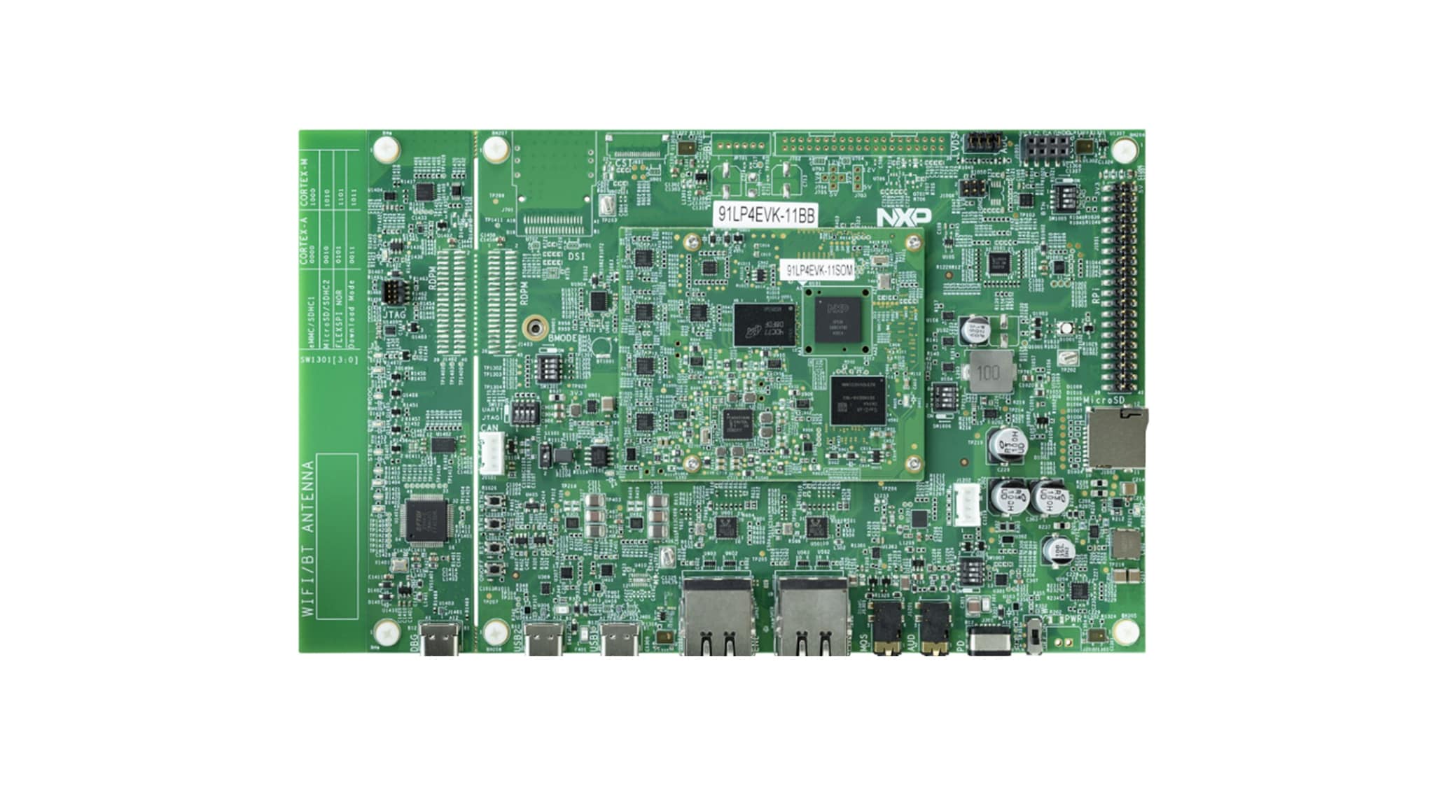
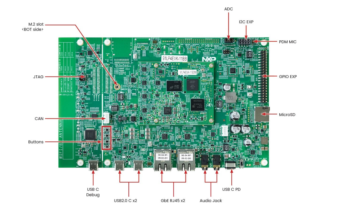
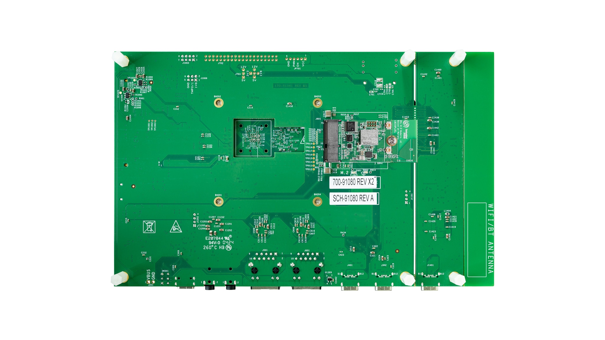
1.1 Get Familiar with the Board
1.2 System Requirements
- Windows: Windows 7 or later version
- Ubuntu: Ubuntu 18.04 or later version
1.3 Power Requirements
- USB C PD 45W, 5V/3A; 9V/3A; 15V/3A; 20V/2.25A supported
1.4 Boot from eMMC
The i.MX 91 EVK comes with a pre-built NXP Linux binary demo image flashed on the eMMC. Without modifying the binary inside, booting from the eMMC provides a default system with certain features for building other applications on top of Linux.
To understand more about NXP's Embedded Linux®, Embedded Android™ or MCUXpresso SDK, continue reading the next sections.
1.5 Connect USB Debug Cable
Connect the supplied USB Type-C cable to the debug UART port J1401, then connect the other end of the cable to a host computer.
Four UART connections will appear on the host computer. The third port is for A55 core system debugging.
If you are unfamiliar with terminal applications, please view one of the following tutorials before continuing to the next step: Minicom Tutorial, Tera Term Tutorial, PuTTY Tutorial.
1.7 Connect Power Supply
- Connect the power supply cable to the power connector (
J301) - Power the board by flipping the switch (
SW1301) - The processor starts executing from the on-chip ROM code. With the default boot switch setup, the code reads the fuses to define the media where it is expected to have a bootable image. After it finds a bootable image, the U-Boot execution should begin automatically
- Information is printed in the serial console for the Cortex® A55. If you do not stop the U-Boot process, it continues to boot the kernel
- After boot process finishes, you can see
imx91evk login:in console. Userootto login, and then you can seeroot@imx91evk:~#in console - Congratulations, Linux Boot is complete
2. Get Software
This section is applicable ONLY if attempting to load a Linux operating system on the board.
The i.MX Linux Board Support Package (BSP) is a collection of binary files, source code and support files that are used to boot an Embedded Linux image on a specific i.MX development platform.
Current releases of Linux binary demo files can be found on the i.MX Linux download page. Additional documentation is available in the i.MX Linux documentation bundle under the Linux sections of the i.MX Software and Development Tools.
2.1 Overview
Before the Linux OS kernel can boot on an i.MX board, the Linux kernel is loaded to a boot device (SD card, eMMC and so on) and the boot switches are set to boot that device.
There are various ways to download the Linux BSP image for different boards and boot devices.
This Getting Started guide only outlines a few methods of transferring the Linux BSP to an SD card. Experienced Linux developers can explore other options if desired.
2.2 Download an NXP Linux BSP Pre-Built Image
The latest pre-built images for the i.MX 91 EVK are available on the Linux download page under the most current version on Linux.
The pre-built NXP Linux binary demo image provides a typical system and basic set of features for using and evaluating the processor. Without modifying the system, the users can evaluate hardware interfaces, test SoC features and run user space applications.
When more flexibility is desired, an SD card can be loaded with individual components (bootloader, kernel, dtb file and rootfs file) one-by-one or the .wic image is loaded and the individual parts are overwritten with the specific components.
2.3 Burn NXP Linux BSP Image Using Universal Update Utility (UUU)
In addition to the connections from "Out of the Box" section, connect the USB1 to the host machine using the proper USB cable.
Turn off the board. Consult the "1.4 Boot Switch Setup" section and configure the board to boot in serial download protocol (SDP) mode.
Depending on the OS used in the host machine, the way to transfer the Linux BSP image onto an SD card can vary. Choose an option below for detailed instructions:
Linux®
Install UUU on Linux Distro
Download the latest stable files from UUU GitHub page . If further assistance for UUU is needed, please refer to this extensive tutorial .
uuulibusb1(via apt-get or any other package manager)
Burn the NXP Linux BSP Image to the Board
The latest pre-built images for the i.MX 91 EVK are available on the Linux download page under the most current version of Linux.
The pre-built NXP Linux binary demo image provides a typical system and basic set of features for using and evaluating the processor. Without modifying the system, the users can evaluate hardware interfaces, test SoC features and run user space applications.
When more flexibility is desired, an SD card can be loaded with individual components (bootloader, kernel, dtb file and rootfs file) one-by-one or the .wic image is loaded and the individual parts are overwritten with the specific components.
By default, this procedure flashes the image to the eMMC flash. Check the UUU GitHub page for reference on how to flash the image to other devices.
- Open a terminal application and change the directory to the location where
uuuand the latest Linux distribution for i.MX 91 EVK are located. Add execution permission to theuuufile and execute it.uuuwill wait for the USB device to connect - Turn on the board,
uuuwill start to copy the images to the board - When it finishes, turn off the board and console. For further assistance with configuring the board to boot from eMMC, please consult the Boot Switch Setup
$ chmod a+x uuu
$ sudo ./uuu -b emmc_all imx-image-full-imx91evk.wic Windows™
Install UUU on Linux Distro
Download the latest stable files from UUU GitHub page . If further assistance for UUU is needed, please refer to this extensive tutorial .
uuu.exe- Serial USB drivers (depending on your board and Windows installation - check Windows Device Manager)
Burn the NXP Linux BSP Image to the Board
By default, this procedure flashes the image to the eMMC flash. Check the UUU GitHub page for reference on how to flash the image to other devices.
- Open the command prompt application and navigate to the directory where the
uuu.exefile and the Linux release for the i.MX 91 EVK are located - Turn on the board,
uuuwill start to copy the images to the board - When it finishes, turn off the board and console. For further assistance with configuring the board to boot from eMMC, please consult the Boot Switch Setup
./uuu.exe -b emmc_all imx-image-full-imx91evk.wic Minicom Tutorial
Serial Communication Console Setup
On the command prompt of the Linux host machine, run the following command to determine the port number:
$ ls /dev/ttyUSB*The third number is for Arm® Cortex®-A55.
Minicom Tutorial
Use the following commands to install and run the serial communication program (minicom as an example):
- Install Minicom using the Ubuntu package manager
- Launch Minicom using a console window using the port number determined earlier
- Configure Minicom as shown in Figure and Exit configure
- The next step is to Boot Switch Setup
$ sudo apt-get install minicom$ sudo minicom /dev/ttyUSB* -s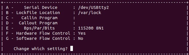
Tera Term Tutorial
Serial Communication Console Setup
The FTDI USB-serial chip on i.MX 91 enumerates 4 serial ports. Assume that the ports are COM11, COM12, COM13, COM14. The third port (COM13) is for the serial console communication from Arm® Cortex®-A55. The serial-to-USB drivers are available at FTD Chip Drivers .
Tera Term Tutorial
Tera Term is an open source terminal emulation application. This program displays the information sent from the NXP development platform's virtual serial port.
- Download Tera Term. After the download, run the installer and then return to this webpage to continue
- Launch Tera Term. The first time it launches, it shows the following dialog. Select the serial option. Assuming your board is plugged in, there should be a COM port automatically populated in the list
- Configure the serial port settings (using the COM port number identified earlier) to 115,200 baud rate, 8 data bits, no parity and 1 stop bit. To do this, go to Setup → Serial Port and change the settings
- Verify that the connection is open. If connected, Tera Term shows something like below in its title bar
- The next step is to Boot Switch Setup
PuTTY Tutorial
Serial Communication Console Setup
The FTDI USB-serial chip on i.MX 91 enumerates 4 serial ports. Assume that the ports are COM11, COM12, COM13, COM14. The third port (COM13) is for the serial console communication from Arm® Cortex®-A55. The serial-to-USB drivers are available at FTD Chip Drivers.
PuTTY Tutorial
PuTTY is a popular terminal emulation application. This program displays the information sent from the NXP development platform's virtual serial port.
- Download PuTTY. After the download, run the installer and then return to this webpage to continue
- Launch PuTTY by either double clicking on the executable file you downloaded or from the Start menu, depending on the type of download you selected
- Configure In the window that launches. Select the Serial radio button and enter the COM port number that you determined earlier. Also, enter the baud rate, in this case 115,200
- Click Open to open the serial connection. Assuming the board is connected and you entered the correct COM port, the terminal window opens. If the configuration is not correct, PuTTY will alert you
- The next step is to Boot Switch Setup
On this page
- 1.1
Get Familiar with the Board
- 1.2
System Requirements
- 1.3
Power Requirements
- 1.4
Boot from eMMC
- 1.5
Connect USB Debug Cable
- 1.6
Boot Switch Setup
- 1.7
Connect Power Supply