Getting Started with the KIT-STBI-A8971 Evaluation Board
Contents of this document
-
Out of the Box
-
Get Hardware
-
Install Software
-
Configure Hardware
Sign in to save your progress. Don't have an account? Create one.
Purchase your FXLS8971CF Development Board
1. Out of the Box
The NXP analog product development boards provide an easy-to-use platform for evaluating NXP products. The boards support a range of analog, mixed-signal and power solutions. They incorporate monolithic integrated circuits and system-in-package devices that use proven high-volume technology. NXP products offer longer battery life, a smaller form factor, reduced component counts, lower cost and improved performance in powering state-of-the-art systems.
This page will guide you through the process of setting up and using the FRDM-STBI- A8971 board.
1.1 Kit Content and Packing List
The KIT-STBI-A8971 kit contents include:
- KIT-STBI-A8971: FXLS8971CF sensor shield board
- USB cable
- Quick Start Guide
1.2 Software References
The following sensors toolbox developer resources are recommended to jump-start your evaluation or development using KIT-STBI-A8971 sensor evaluation board:
2. Get Hardware
2.1 Board Features
- Sensor evaluation board for FXLS8971CF is offered as sensor kit with LPC55S16-EVK
- Enables quick sensor evaluation and helps accelerate quick prototyping and development using FXLS8971CF 3-axis accelerometer
- Compatible with Arduino and most NXP FRDM development boards
- Supports I²C and SPI communication interface with host MCU
- Supports hardware configurability to switch between accelerometer mode (normal vs. motion detect) and I²C/SPI interface mode
- Supports multiple test points on shield board
2.2 Board Description
The KIT-STBI-A8971 is a sensor add-on/expansion shield board for FXLS8971CF 3-axis low-power accelerometer with excellent offset and sensitivity stability over temperature.
KIT-STBI-A8971 sensor shield board is kitted with a LPC55S16-EVK MCU board to enable quick customer evaluation of FXLS8971CF using sensor toolbox enablement SW and tools.
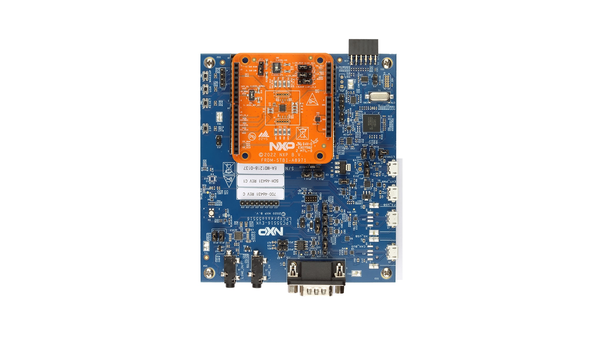
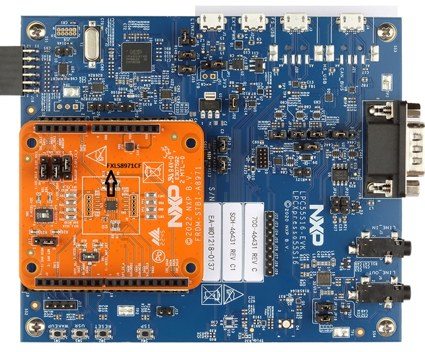
2.3 Board Components
Overview of the KIT-STBI-A8971 board
3. Install Software
3.1 Install Software
Follow the getting started instructions provided for following sensors development software tools to jump-start your evaluation or development using FRDM-STBA-A8971 sensor shield board kitted with LPC55S16-EVK:
4. Configure Hardware
4.1 Configure the Hardware
- Check and confirm KIT-STBI-A8971 Sensor shield board settings as described below:
- To select I²C digital interface, connect pins 2-3 of
SW2on KIT-STBI-A8971 - Connect
J7,J8pins 1-2 to select I2C0 pins on shield board - To select SPI digital interface, connect pins 1-2 of
SW2on KIT-STBI-A8971 - Connect pins 2-3 of
SW1to select default accelerometer operating mode i.e. "ACCEL NORMAL" mode
- To select I²C digital interface, connect pins 2-3 of
- Connect KIT-STBI-A8971 Sensor shield board to LPC55S16-EVK MCU board on Arduino I/O headers.
- Connect the Sensor evaluation kit (KIT-STBI-A8971 kitted with LPC55S16-EVK) to the windows PC via the USB cable between the LINK2 USB port on the board and the USB connector on the PC.
Design Resources
Board Information
Additional References
In addition to our FXLS8971CF, ±2g/±4g/±8g/±16g, Low Power 12-Bit Digital Accelerometer page, you may also want to visit: