Getting Started with the KIT-TPLSNIFEVB Tool
Contents of this document
-
Get Started
-
Get Hardware
-
Configure Hardware
-
Get Software
Sign in to save your progress. Don't have an account? Create one.
Purchase your KIT-TPLSNIFEVB
1. Get Started
This page will guide you through the process of setting up and using the KITTPLSNIFEVB tool.
1.1 Kit Contents and Packing List
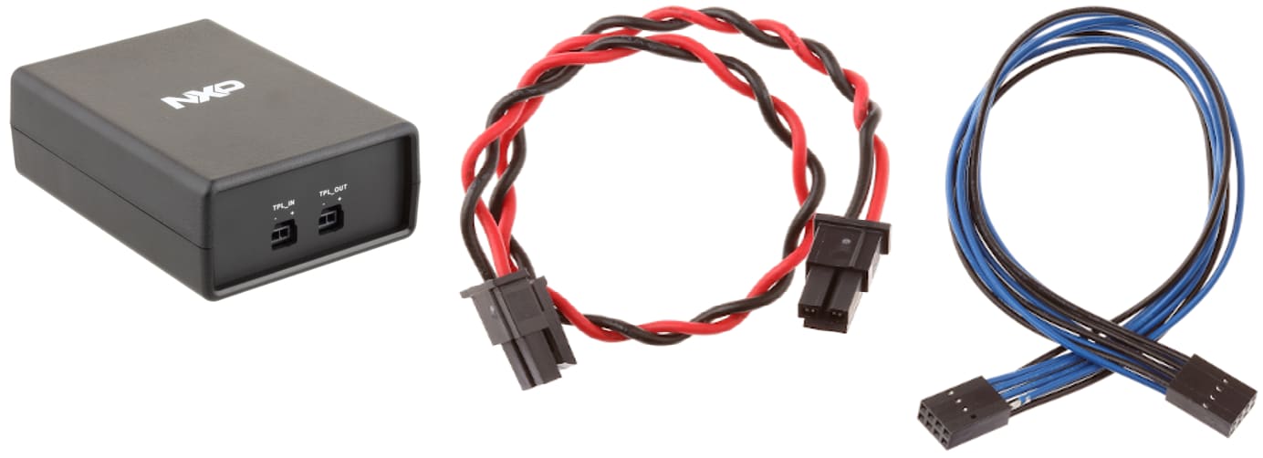
The KIT-TPLSNIFEVB contents include:
- Assembled and tested TPL sniffer dongle in anti-static bag
- A logic analyzer connection cable with 8-pin headers
- An ETPL bus connection twisted cable with 2-pin headers
1.2 Additional Hardware and Software
The TPL sniffer requires only a 5.0 V with 50 mA (average) and 150 mA (peak) power supply through a USB Micro-B connector (for example, a power bank, or a USB cable connected to a computer).
To analyze the data sourced from the TPL sniffer a logic analyzer (for example, Saleae Logic Analyzer) is required along with its software.
Optionally, plug-ins and extensions to add to the Saleae Logic Analyzer software have been developed in order to decode TPL frames. For additional details, visit section 4.
1.3 User Manual
Refer to UM11650, KIT-TPLSNIFEVB tool for additional details on the featured components and board configuration.
2. Get Hardware
2.1 Board Features
- Internal galvanic isolation between the ETPL function and rest of the circuits
- Connection to any point of the monitored ETPL bus
- Minimal loading of the ETPL line
- Logic analyzer connection, with a provided cable pin-to-pin compatible with the Saleae Logic 8 and Logic Pro 8/16 Analyzer series
- Powered through a USB connector by a 5.0 V source, typically a USB power bank or a USB cable connected to a computer
- Integrated keep-alive function to avoid power bank self shut-off
2.2 Board Description
The KIT-TPLSNIFEVB board, also called TPL sniffer is working with a logic analyzer (preferably a Saleae Logic Analyzer) and its software to help analyze electrical transport protocol link (ETPL) signals.
Placed in any ETPL bus, it non-intrusively listens to all messages and monitors the frame traffic on the bus (the TPL sniffer works in listen mode only). The corresponding received data (in SPI format) is available on the ANALYZER output connector, to be connected to a logic analyzer and its software which provides further analysis of such data.
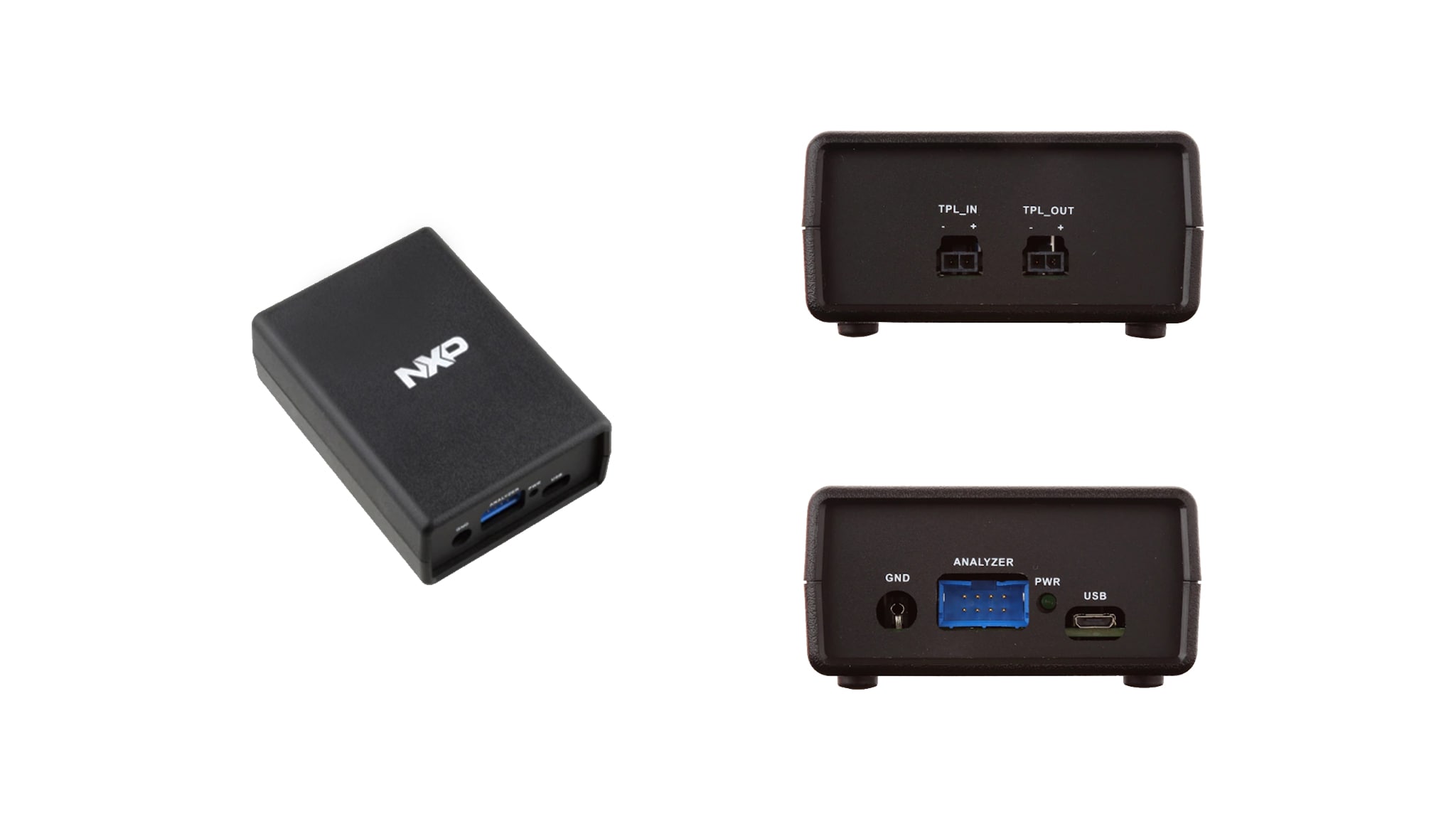
2.3 Board Components
Overview of the KIT-TPLSNIFEVB tool
3. Configure Hardware
The TPL sniffer exposes a set of connectors on two sides. One side is dedicated to the ETPL bus connection and on the other side all other connectors are present. The two sides are galvanically isolated from each other: the ETPL bus connectors are isolated from all other accessible points on the housing.
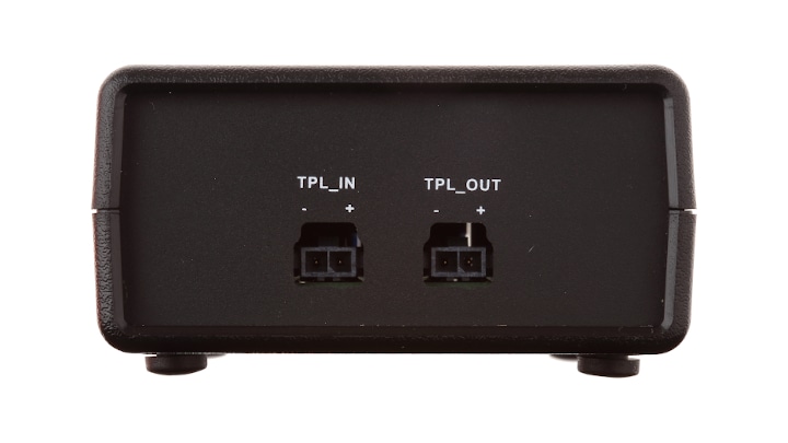
3.1 Connecting to the ETPL Bus
The ETPL connectors are located on one side of the housing and are marked TPL_IN and TPL_OUT with a polarity indication + and -. The correct polarity of the connection is mandatory for the proper functioning of the sniffer and, in most cases, also for the system to be sniffed.
Conversely, the terms IN and OUT are conventional and the two connectors are electrically in parallel inside the TPL sniffer. They are physically duplicated to make it easier to connect the wires in certain use cases. For example, in the case of a daisy chain, the original ETPL bus is cut and the two ends must be plugged onto the receptacles of the TPL sniffer. In other cases, for example, when the ETPL bus has only one differential end available for connection to the TPL sniffer, there is no difference between the TPL_IN and TPL_OUT connectors, as long as the polarity is respected.
As a rule, if a stub is created from the original ETPL bus, its length should be as short as possible.
3.2 Optional ETPL Bus Loading
The TPL sniffer is designed to add minimal load to the ETPL bus by default. Therefore, it does not add any termination impedance and the differential load seen from the bus is that of an input impedance of the MC33664 reflected on the high voltage side by the 1:1 ratio T1 isolation transformer.
In case an interface other than the default one is desired; some settings are possible on the PCB:
- The two jumpers
JP1andJP2located on the bottom side, should be closed (with a drop of solder) in case a standard 150 Ω termination is desired - Additional component footprints are available on the top side of the PCB to accommodate different loads on the TPL
bus interface. These are
R13(default DNP) andR14andR15(default 0 Ω)
3.3 Power and Data Connections
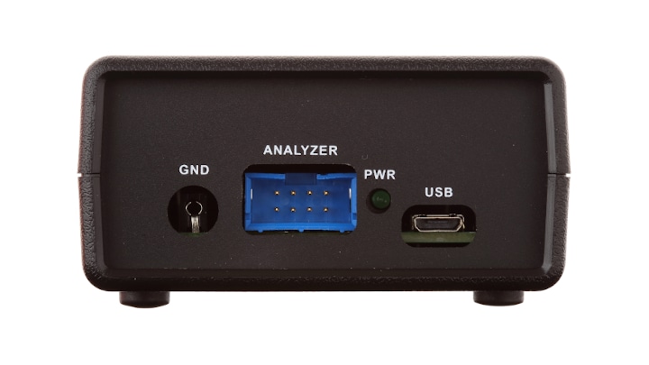
The side of the case opposite the ETPL connectors has all the other available connectors of the TPL sniffer.
- The GND banana plug: used to connect, if necessary, the GND of the TPL sniffer to another potential. It is labeled
J5in the schematics. In some cases of use, the whole system including, for example, the TPL sniffer, the power supply, the logic analyzer and the associated PC, could be an electrically floating block. This connector allows, if desired, the ground potential of the system (for example, the TPL sniffer and anything else that has its ground connected to the TPL sniffer ground) to be set to any other convenient potential, that is, the protective earth or the vehicle chassis ground (KL31) - The data-out 8-pin connector: buffered SPI signals to be routed to the logic analyzer. It is labeled
J3in the schematics - The power-on LED indicator UM11650 All information provided in this document is subject to legal disclaimers. © NXP B.V. 2021. All rights reserved. User manual Rev. 1 — 29 July 2021 7 / 14 NXP Semiconductors UM11650 KIT-TPLSNIFEVB tool
- The USB Micro-B connector: to connect to a 5.0 V source. It is labeled
J4in the schematics
3.4 Connecting to the Logic Analyzer
The data output connector (J3) is an 8-pin 4x2 male connector used as an interface to the logic analyzer, to transfer
TPL messages converted to SPI format.
The signals are all unidirectional and their direction is from the TPL sniffer (output) to the logic analyzer (input).
The TPL sniffer is designed such that the cable connection to the logic analyzer can be relatively long, with a maximum length of 2 m, without loss of signal integrity and therefore maintaining the logic and timing information.
This statement is only true if the following two rules are both satisfied:
- The cable used for the connection must have a characteristic impedance of 100 Ω. This is the impedance normally found on standard IDC ribbon cables
- The logic analyzer side of the cable should only be loaded with high impedance terminations such as a High-Z input from an oscilloscope, for example, 15 pF || 1 MΩ, or 5 pF || 10 MΩ (better), or digital inputs from a logic analyzer (for example, 10 pF || 2 MΩ)
Failure to follow these rules does not guarantee proper operation of the TPL sniffer, unless the cable length is considerably short (< 15 cm) so that reflections in the cable can be neglected.
For signal integrity and EMI reduction, the data lines are interleaved with the ground potential with the pinout described in Table X.
The TPL sniffer data output lines and the ETPL inputs are internally protected by ESD suppression devices. Nevertheless, standard electrostatic precautions should be taken when handling and using the TPL sniffer.
The pin assignment for the data output connector is described in the following table:
| Pin | Signal | Description |
|---|---|---|
| 1 | INTB | SPI interrupt signal |
| 2 | GND | Ground |
| 3 | RXCLK | SPI bus clock |
| 4 | GND | Ground |
| 5 | RXDATA | SPI bus data |
| 6 | GND | Ground |
| 7 | RXCSB | SPI chip select |
| 8 | GND | Ground |
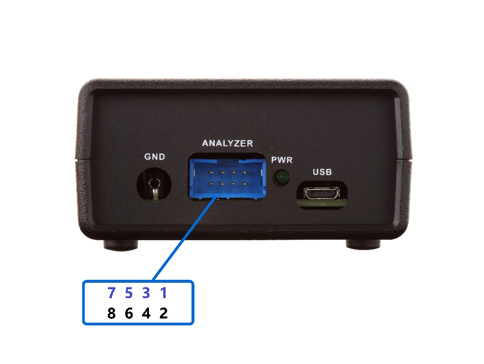
The supplied 8-pin connection cable should be plugged into the ANALYZER connector with the blue wires on top (NXP logo side) and the black wires on the bottom.
3.5 Interfacing with the Saleae Logic Analyzer
The supplied 8-pin connectors cable is fitting the Saleae Logic 8 and Logic Pro 8/16 analyzer series input connectors. To connect to the Saleae Logic Analyzer, the cable should be plugged with the blue wires on top (Saleae logo side) and the black wires on the bottom.
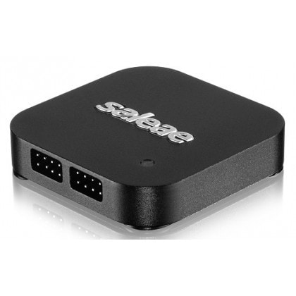
Saleae provides a software interface with its product to help decode the acquired signals. To learn more, visit the Saleae website.
Plug-ins and extensions for the Saleae Logic Analyzer software are available to decode TPL frames. Visit section 4 for more details.
3.6 Powering the TPL Sniffer
The TPL sniffer can be powered through the USB Micro-B connector (J4, labeled PWR) by a 5.0 V source with 50 mA (average) and 150 mA (peak), typically a USB power bank or a USB cable connected to a computer.
3.7 Power Bank Keep-Alive Function
The purpose of the keep-alive feature is to avoid the activation of the automatic shutdown feature found on most consumer USB power banks. Such a shutdown would likely occur due to the limited power consumption of the TPL sniffer circuit alone, in the 10 mA to 20 mA range. Therefore, the sniffer activates an additional 150 mA of internal power consumption with a period of 5.8 seconds and a duty cycle of 20 % (all figures are approximate). This simulates a load large enough to keep most power banks energized.
If the power-on LED indicator goes out shortly after the TPL sniffer is first powered up with a power bank, consider trying another power bank model.
4. Get Software
4.1 TPL Decoder Tool for Saleae Logic Software
The TPL Decoder is a high level analyzer (HLA) extension for the Saleae Logic Software. It helps decoding the NXP TPL protocols on several physical layers.
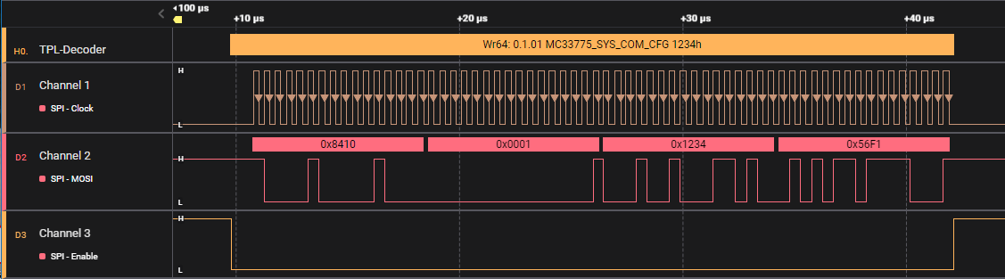
This tool is also part of the NXP BMS communication decoder ecosystem and can work together with the KIT-TPLSNIFEVB hardware board that facilitates the acquisition of electrical transport protocol link (ETPL) signals.
4.2 Package Content
The downloadable package contains the TPL Decoder installer along with a release notes and software content register (SCR) files. More information about supported devices and physical layers covered in the latest version can be found the the release notes file.
4.3 Pre-requisites
The TPL Decoder is a high level analyzer (HLA) extension for the Saleae Logic Software. Therefore the recommended Saleae Logic Software version (see release notes file) must be installed prior to the TPL Decoder installation. Visit the Saleae website to download the Saleae Logic Software.
4.4 Installation
Refer to the release notes file for installation steps.
4.5 Use
Guidance on using TPL Decoder can be found directly in the Saleae Logic Software by clicking on the TPL Decoder in the Extensions menu.
Design Resources
Support
Forums
Connect with other engineers and get expert advice on designing with the KIT-TPLSNIFEVB Tool on one of our community sites.
On this page
- 3.1
Connecting to the ETPL Bus
- 3.2
Optional ETPL Bus Loading
- 3.3
Power and Data Connections
- 3.4
Connecting to the Logic Analyzer
- 3.5
Interfacing with the Saleae Logic Analyzer
- 3.6
Powering the TPL Sniffer
- 3.7
Power Bank Keep-Alive Function