Getting Started with the MPC5775B BMS and VCU Reference Design
Contents of this document
-
Out of the Box
-
Get Software
-
Plug It In
Sign in to save your progress. Don't have an account? Create one.
Purchase your MPC5775B BMS and VCU Reference Design
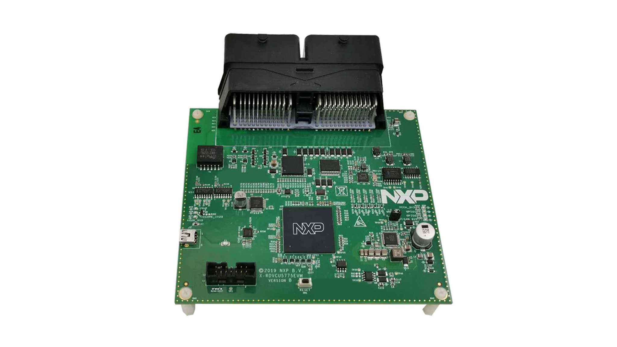
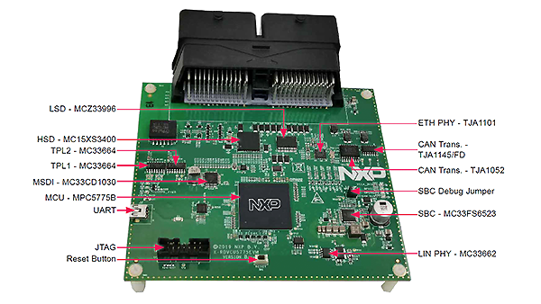
1. Out of the Box
1.1 Get to know your reference design
2. Get Software
2.1 Download the RDVCU5775EVM software development kit (SDK)
S32 Design Studio based demo project for RDVCU5775EVM using SDK 3.0.0 with FreeRTOS.
Download RDVCU5775EVM SDK2.2 Download the RDVCU5775EVM graphic user interface (GUI)
GUI software to monitor battery status via CAN interface.
Download RDVCU5775EVM GUI2.3 Get your integrated development environment (IDE)
RDVCU5775EVM performs better when using S32 Design Studio for Power Architecture 2017.R1
Download S32 Design Studio2.4 Get a GIU run-time environment
Python 3.7 64-bit with PyQt5 and Numpy GUI run-time environment.
Download Python3. Plug It In
3.1 Set up UART driver for RDVCU5775EVM
Connect the mini USB cable to J2 mini USB port on RDVCU5775EVM.
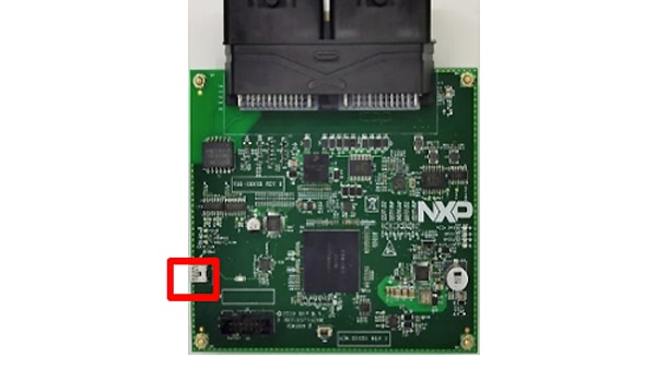
Check if the driver is available under Ports (COM and LPT) in Device Manager.

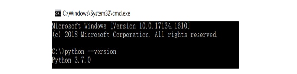
3.2 Set up the GUI environment
Open Windows Command Prompt and execute the python - version to check the python version.
Execute the pip install PyQt5 and pip install Numpy to install the necessary packages for GUI.
Projects and tutorials
Battery Management System (BMS) demo
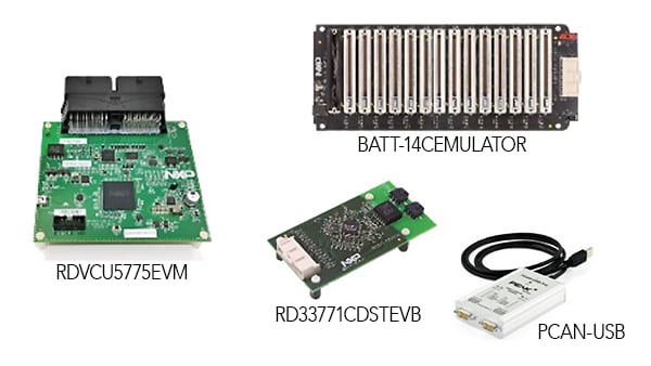
Required Hardware
| Part Number | Description |
|---|---|
| RDVCU5775EVM | MPC5775B BMS and VCU RDB with MC33664 TPL Interface Support |
| RD33771CDSTEVB | MC33771C-Based Battery Cell Controller Evaluation Board |
| BATT-14CEMULATOR | 14 Cell Battery Emulator Board |
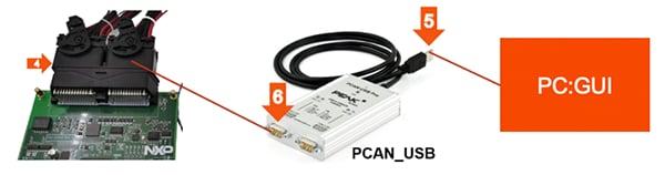
| PCAN-USB adapter | CAN Adapter |
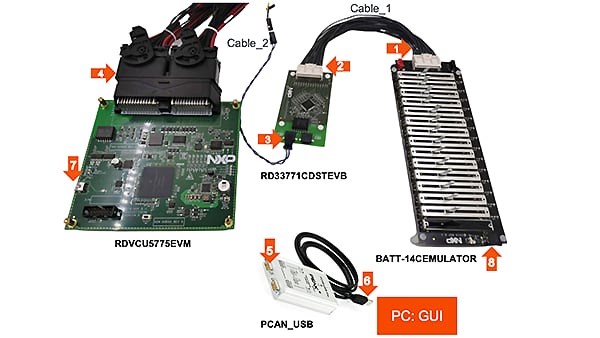
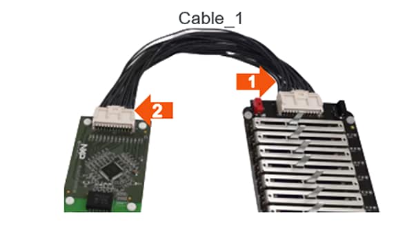
Connect BATT-14CEMULATOR and RD33771CDSTEVB
Connect the battery cell emulator board (BATT-14CEMULATOR) and the battery cell controller board (RD33771CDSTEVB) using Cable_1.
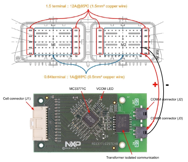
Connect RD33771CDSTEVB and RDVCU5775EVM for TPL link
Connect the battery management controller board (RDVCU5775EVM) with battery cell controller board (RD33771CDSTEVB) using Cable_2. This will establish the TPL link for communication.
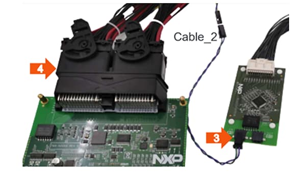
| Connector pin-out | Description |
|---|---|
| M24 | TPL1 negative terminal |
| M25 | TPL1 positive terminal |
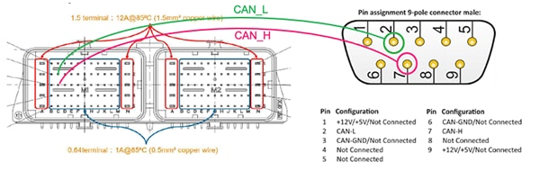
Connect the CAN with PCAN tool
Connect the CAN_H and CAN_L signals of RDVCU5775EVM to PCAN USB CAN_H (pin 7) and CAN-L (pin 2) via
two jumper cables.
| Connector pin-out | Description |
|---|---|
| C12 | CAN1_L |
| D12 | CAN1_H |
Connect the USB serial cable
Connect the RDVCU5775EVM board to PC via the USB serial cable.
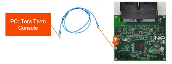
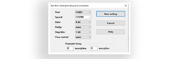
Setup Tera Term Console
Open Tera Term on Windows® PC.
Select the serial port to which the micro USB of the development board is connected and click OK.
Go to Setup → Serial Port and select 115200 as the baud rate.
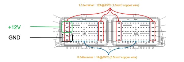
Power up RDVCU5775EVM
Connect 12 V power supply to RDVCU5775EVM.
Make sure the status LEDs D14, D15, D16 and D32 for voltage levels 3.3 V, 5 V, 1.25 V and 12 V supply respectively are glowing yellow on the board.
Power up BATT-14CEMULATOR and RD33771CDSTEVB
Connect the power supply to the BATT-14CEMULATOR. RD33771CDSTEVB is powered at the same time.

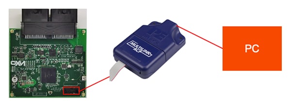
Connect the P&E Multilink between PC and RDVCU5775EVM board
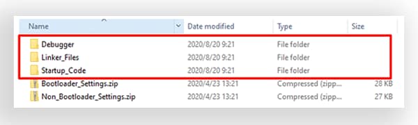
Preparation before importing the SDK project
Unzip the file Bootloader_Settings.zip that is located in [PROJECT_DIR] \PDC_5775B_SDK_Z7_0\Project_Settings to replace the folders.
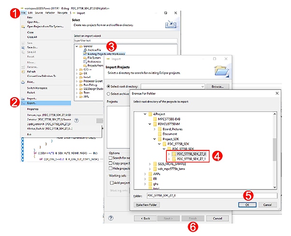
Import the SDK project to S32DS
S32 Design Studio for Power Architecture@ 2017.R1.
S32 Design Studio for Power Architecture 2017.R1 Update 11 SDK PA RTM 3.0.0.
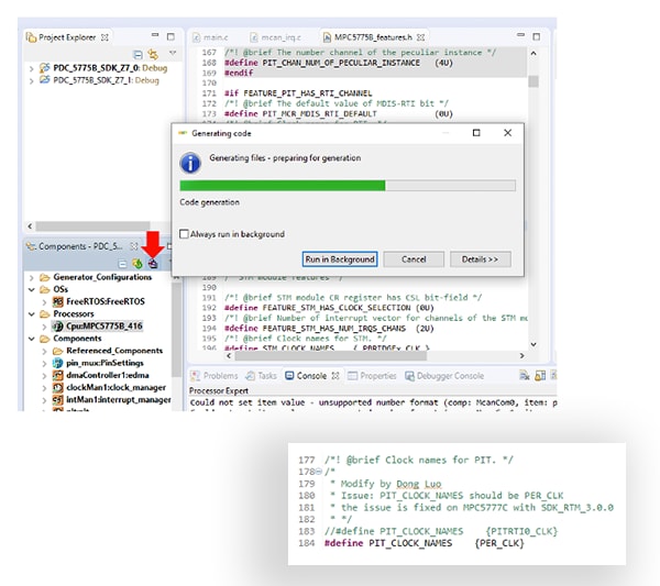
Generate processor expert codes
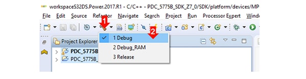
Debug your code
Select “Debug” and click the hammer icon to build the project.
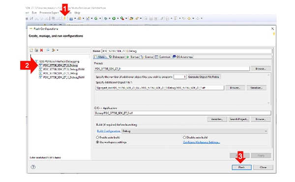
Download to the MCU
Download the elf file to MCU.
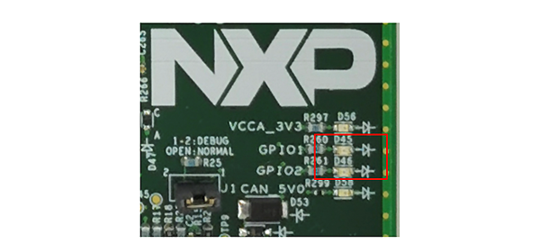
Check the running status of the application
LEDs D45 and D46 on RDVCU5775EVM board should blink at different frequencies.
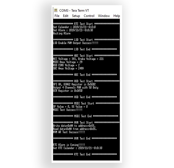
The board self-test message should be shown on the terminal.
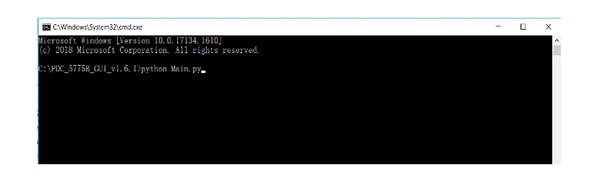
Run the GUI software
Open the windows “Command Prompt” and execute the python Main.py in the command shell.
Make sure you first install the Python 3.7 64-bit version and necessary packages PyQt5 and NumPy prior to the above step.
Refer to the readme file in the downloaded software GUI folder.
Setup the GUI connection via PCAN USB
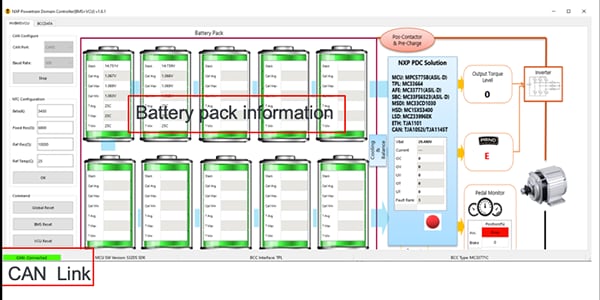
Select CAN Port and CAN baud rate to 500Kbps. Click “Start” to establish the connection with RDVCU5775EVM. Click “BMS Reset” to reset the BMS task in application. Input the related NTC parameters and click “OK”.
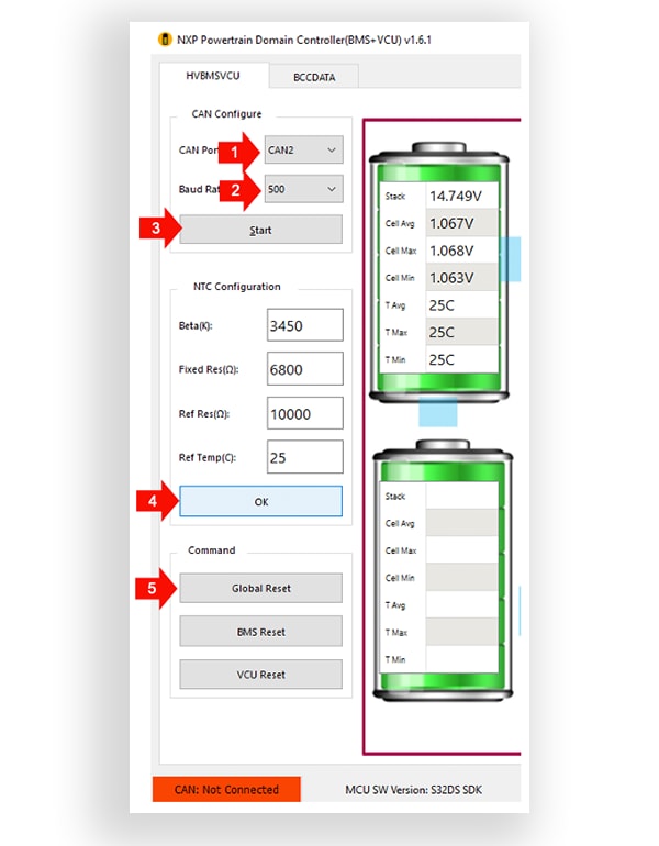
System running information including CAN connection status, MCU software version, battery pack information after communication has been established:
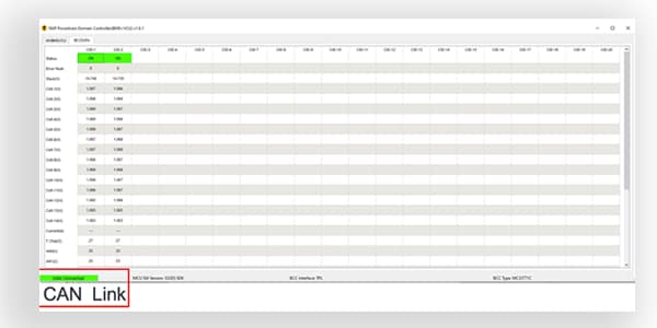
Adjust the battery levels via BATT-14CEMULATOR and observe the GUI for individual cell data in “BCCDATA” tab.
Design Resources
Board Documents
Chip Documents
Support
Forums
Connect with other engineers and get expert advice on designing with the RDVCU5775EVM on one of our community sites.
On this page
- 2.1
Download the RDVCU5775EVM software development kit (SDK)
- 2.2
Download the RDVCU5775EVM graphic user interface (GUI)
- 2.3
Get your integrated development environment (IDE)
- 2.4
Get a GIU run-time environment
- 2.5
Get a UART driver
- Battery Management System (BMS) demo
- Connect BATT-14CEMULATOR and RD33771CDSTEVB
- Connect RD33771CDSTEVB and RDVCU5775EVM for TPL link
- Connect the CAN with PCAN tool
- Connect the USB serial cable
- Setup Tera Term Console
- Power up RDVCU5775EVM
- Power up BATT-14CEMULATOR and RD33771CDSTEVB
- Connect the P&E Multilink between PC and RDVCU5775EVM board
- Preparation before importing the SDK project
- Import the SDK project to S32DS
- Generate processor expert codes
- Debug your code
- Download to the MCU
- Check the running status of the application