Getting Started with the OM2385-SF002 Evaluation Board
Contents of this document
-
Get Started
-
Get to Know the Hardware
-
Install the Software
-
Install software
Sign in to save your progress. Don't have an account? Create one.
Purchase your OM2385-SF002 - SIGFOX Development Kit
Get Started
The NXP analog product development boards provide an easy-to-use platform for evaluating NXP products. The boards support a range of analog, mixed-signal and power solutions. They incorporate monolithic integrated circuits and system-in-package devices that use proven high-volume technology. NXP products offer longer battery life, a smaller form factor, reduced component counts, lower cost and improved performance in powering state-of-the-art systems.
This page will guide you through the process of setting up and using the OM2385/SF002 development kit.
1.1 Kit Contents/Packing List
The OM2385/SF002 development kit contents include:
- Assembled and tested board mounted to a firmware loaded FRDM-K32L2B3 board
- Antenna
- USB cable
- Quick Start Guide
1.2 Windows PC Workstation
This evaluation board requires a Windows PC workstation. Meeting these minimum specifications should produce great results when working with this kit.
- USB enabled computer running Windows XP, Vista, 7, 8 or 10 (32-bit or 64-bit)
- Terminal emulation software (such as TeraTerm or HyperTerminal)
Get to Know the Hardware
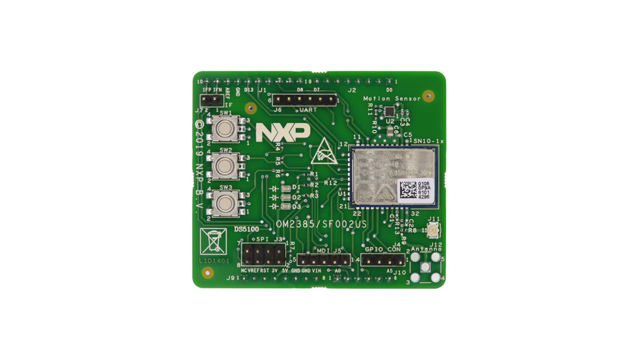
2.1 Board Description
The OM2385/SF002 development kit provides an evaluation platform for designing SIGFOX network applications that use NXP's OL2385 single-chip RF transceiver.
The kit consists of three boards: the OL2385 Shield Board, the OL2385 Innocomm Module and a FRDM-K32L2B3 board. The OL2385 Innocomm Module is permanently affixed to the surface of the OL2385 Shield Board. The Innocomm Module contains an embedded OL2385 transceiver and serves as a wireless modem. When connected to an antenna (included in the kit), it provides all the functionality required to communicate with the SIGFOX network. The OL2385 Shield Board contains connectors for external communication. The Shield Board is mounted by means of four Arduino™ connectors to the FRDM-K32L2B3. The FRDM-K32L2B3 acts as the communication link between the development kit and a PC. It comes preloaded with microcode that manages the interface between the PC and the OL2385 Innocomm Module.
2.2 Board Features
- Arduino connector compatibility with other Freedom boards
- Support for UART, SPI, MDI and GPIO communication
- SIGFOX Communication Library for RC1 through RC7
2.3 Board Components
Overview of the OM2385/SF002 development kit.
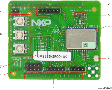
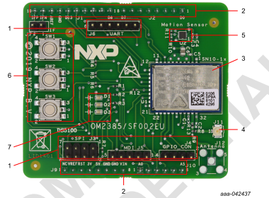
Table 1. Board Component Descriptions
| Number | Name | Description |
|---|---|---|
| 1 | Communication connectors | Provide connectivity for SPI, MDI, GPIO and UART support |
| 2 | Arduino™ connectors | Provide connectivity to FRDM-K32L2B3 and other Freedom boards |
| 3 | Innocomm module | Low-Power Multi-Channel UHF RF Wireless Platform |
| 4 | μFL connector | Provide connectivity to UHF antenna |
| 5 | Motion sensor | Provide wake-up functionality for the Innocomm module |
| 6 | Button switches | Control digital inputs to Arduino™ connectors |
| 7 | LEDs | Indicate status |
Install the Software
3.1 Configure the Hardware
To configure the hardware and workstation, complete the following procedure:
- Check to assure that the OM2385/SF002 board is firmly attached to the FRDMK32L2B3. When connecting the boards, the three switches on the shield board should be on the same side as the USB ports on the FRDM-K32L2B3 board
- Attach the PCB antenna (included with the kit) by snapping the uFL connector on the antenna to the uFL connector on the shield board
- Connect the Standard A end of the supplied USB cable to a Windows host PC.
Connect the Mini B to the FRDM-K32L2B3 USB port labeled SDA (
J13)
Install software
- Configure the terminal emulator
- Get the COM port number for the FRDM-K32L2B3
- Set up the serial port
- Get the Device ID and the Portable Access Code (PAC) for the modem
- Activate a SIGFOX account and register the device
- Verify that the board is successfully sending and receiving messages on the SIGFOX network.
Design Resources
Board Documents
Support
Forums
Connect with other engineers and get expert advice on designing with the OM2385/SF002 evaluation board on one of our community sites.