- Analog Toolbox
- Getting Started with the PCA9957HN-ARD Evaluation Board
Getting Started with the PCA9957HN-ARD Evaluation Board
Contents of this document
-
Out of the Box
-
Plug It In
-
Get Software
-
Configure Hardware
Sign in to save your progress. Don't have an account? Create one.
Purchase your PCA9957HN-ARD LED Driver Arduino® Shield Evaluation Board
1. Out of the Box
The NXP analog product development boards provide an easy-to-use platform for evaluating NXP products. The boards support a range of analog, mixed-signal and power solutions. They incorporate monolithic integrated circuits and system-in-package devices that use proven high-volume technology. NXP products offer longer battery life, a smaller form factor, reduced component counts, lower cost and improved performance in powering state-of-the-art systems.
This page will guide you through the process of setting up and using the PCA9957HNARD evaluation board.
1.1 Kit contents/packing List
The PCA9957HN-ARD contents include:
- Assembled and tested evaluation board in an anti-static bag
- Quick start guide
1.2 Assumptions
Familiarity with the SPI bus is helpful but not required.
1.3 Static Handling Requirements
This device is sensitive to ElectroStatic Discharge (ESD). Therefore care should be taken during transport and handling. Use a ground strap or touch the PC case or other grounded source before unpacking or handling the hardware.
1.4 Minimum System Requirements
This evaluation board requires a Windows PC workstation. Meeting these minimum specifications should produce great results when working with this evaluation board.
- PC with Windows 10 operating system
- One USB port (either 3.0 or 2.0 compatible)
- One of three EVK boards (MIMXRT1050-EVK, LPC55S69-EVK, 8MMINILPD4-EVK) along with the associated firmware and GUI software
- USB cable for power and data connection between the PC and the EVK board (not included in the PCA9957HN-ARD expansion board package)
2. Plug It In
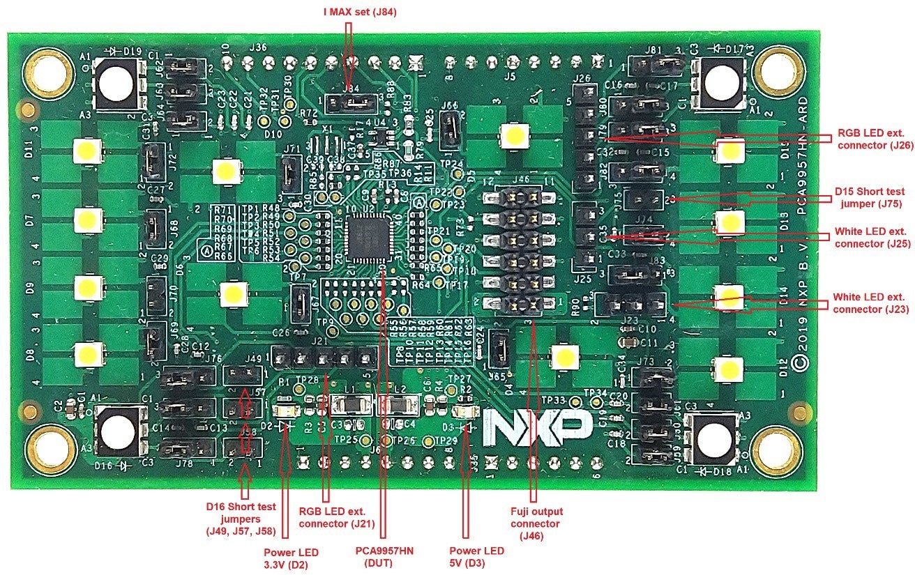
2.1 Board Features
- Combined Arduino port / Fuji connector for data and power
- Multiple board connections in stack architecture
- On-board LEDs for all 24 outputs of the DUT
- On-board jumpers for LED connection, and short tests
- On-board connectors for external LEDs
- Fully compliant with IMXRT1050 EVK board, including GUI (Windows 10)
- Fully compliant with LPCXpresso55S69 dev. board, including GUI (Windows 10)
- Compliant with i.MX Mini LPDDR4 EVK board, including GUI for Windows 10
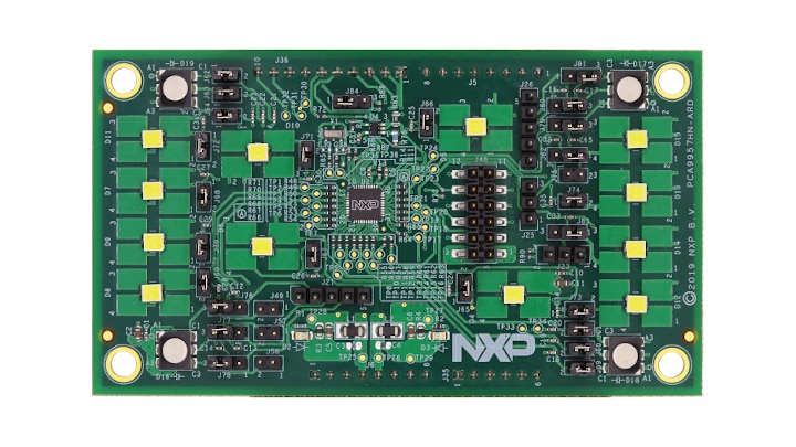
2.2 Board Description
The evaluation board is built around the PCA9957HN, a 24-channel SPI serial bus 32 mA / 5.5 V constant current LED driver produced by NXP Semiconductors. The evaluation board serves as a daughter card that can be connected through an Arduino port to various Arduino compatible (including original Arduino Uno R3) EVK / mother boards for the purpose of testing and measuring the characteristics of the PCA9957HN Device Under Test (DUT).
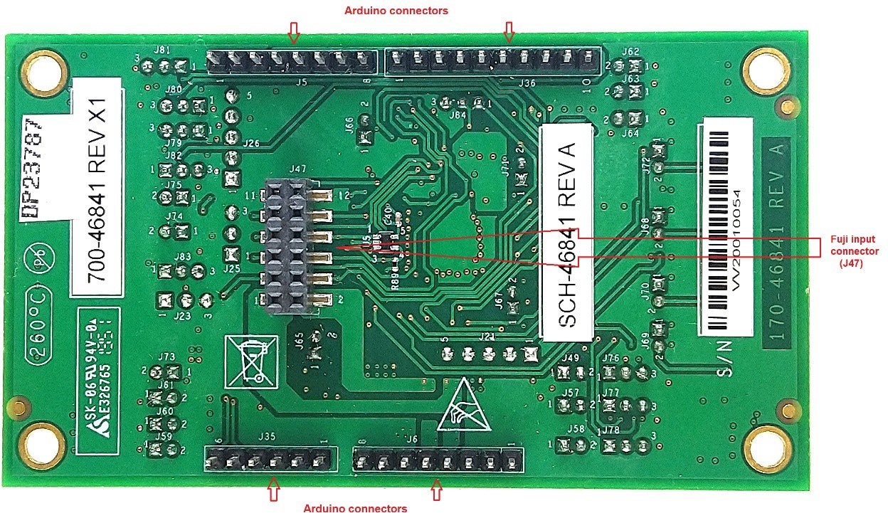
The PCA9957HN host device communicates through the Arduino port with the LED driver via the high-speed SPI bus (up to 10MHz clock frequency). The board is equipped with a pair of Fuji connectors that supports a SPI daisy chain scalable architecture. Thus, users can create a stack of similar boards that share the same SPI bus. The Fuji connectors are of the board-to-board type, allowing the user to attach the boards in a vertical stack instead of connecting link cables between the boards. Three additional digital lines in the SPI bus allow the mother board to control the DUT through the Arduino port or the Fuji connectors.
Power is delivered from the mother board (EVK) through the Arduino port. The power rails are shared with the Fuji connectors, so the DUT can be powered either from the Arduino connectors or the Fuji connectors.
The board contains four RGB LEDs and twelve white LEDs allocated to all twenty-four outputs of the PCA9957HN DUT. The board also contains jumpers and connectors that allow users to connect external LEDs to PCA9957HN outputs.
3. Get Software
PCA9957HN-ARD evaluation board is designed and built as a expansion board able to work with a mother board equipped with an Arduino port. The board is built to be fully compatible with the following NXP evaluation boards:
Each of the above evaluation / development boards is supported by firmware that can be downloaded from the NXP site. Before beginning to use a paired EVK – PCA9957HNARD configuration, the EVK motherboard must be programmed with the corresponding firmware package.
Additionally, a GUI application (Windows 10) is available for download from the NXP site, allowing rapid testing and operation of the PCA9957HN-ARD expansion board in conjunction with the EVK.
The GUI application is common for all three EVKs and for the PCA9xxx LED Controller development card family, manufactured by NXP (PCA9957, PCA9959 and PCA9955B ICs). For details regarding installation of the EVK firmware and GUI host software, see UM11581 , Arduino shields GUI and firmware installation manual.
Once the software is installed, the first step is to select the correct EVK from the graphical interface. The board can then be controlled from the GUI interface.
3.1 Install Software
PCA9957HN-ARD evaluation board is designed and built as a expansion board able to work with a mother board equipped with an Arduino port. The board is built to be fully compatible with the following NXP evaluation boards:
Each of the above evaluation / development boards is supported by firmware that can be downloaded from the NXP site. Before beginning to use a paired EVK – PCA9957HNARD configuration, the EVK motherboard must be programmed with the corresponding firmware package.
Additionally, a GUI application (Windows 10) is available for download from the NXP site, allowing rapid testing and operation of the PCA9957HN-ARD expansion board in conjunction with the EVK.
The GUI application is common for all three EVKs and for the PCA9xxx LED Controller development card family, manufactured by NXP (PCA9957, PCA9959 and PCA9955B ICs). For details regarding installation of the EVK firmware and GUI host software, see UM11581 , Arduino shields GUI and firmware installation manual.
Once the software is installed, the first step is to select the correct EVK from the graphical interface. The board can then be controlled from the GUI interface.
4. Configure Hardware
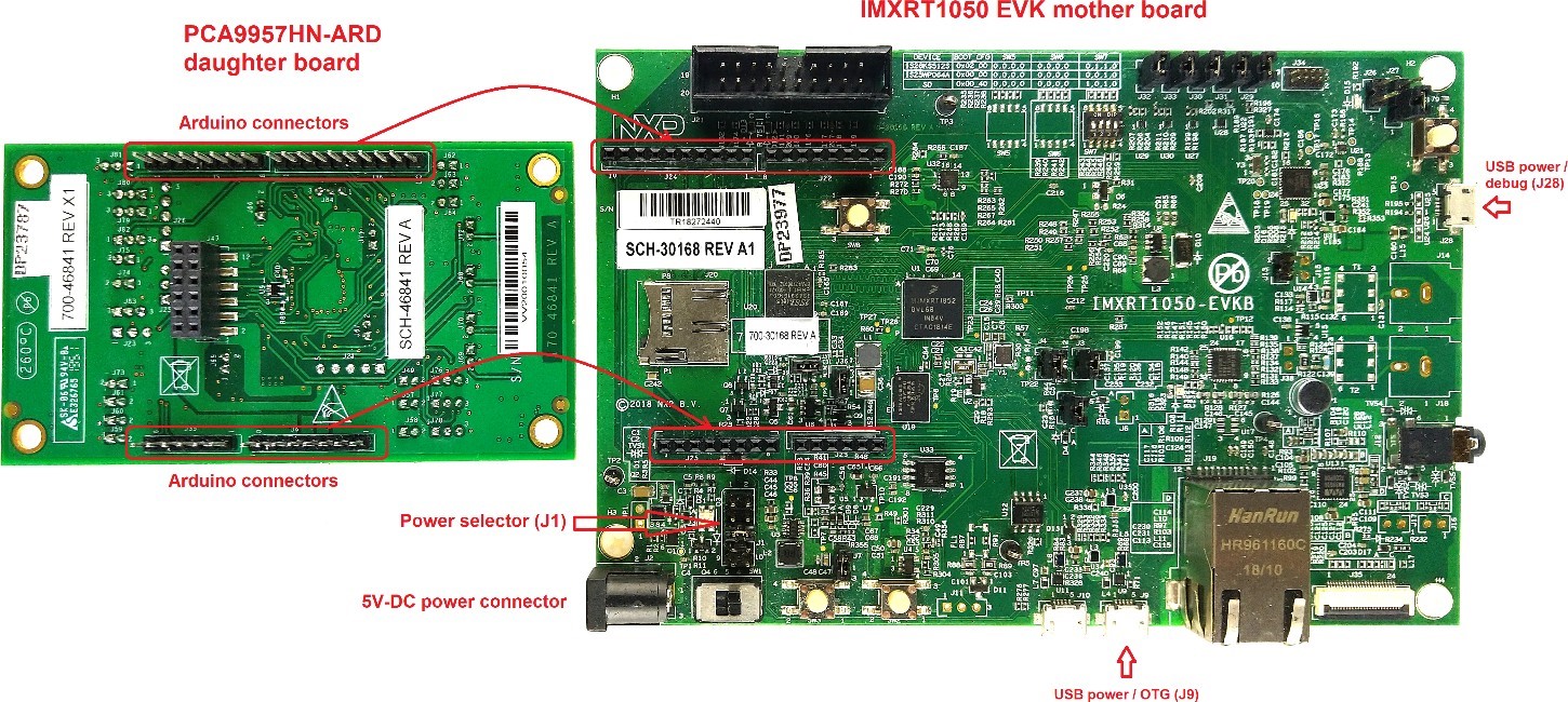
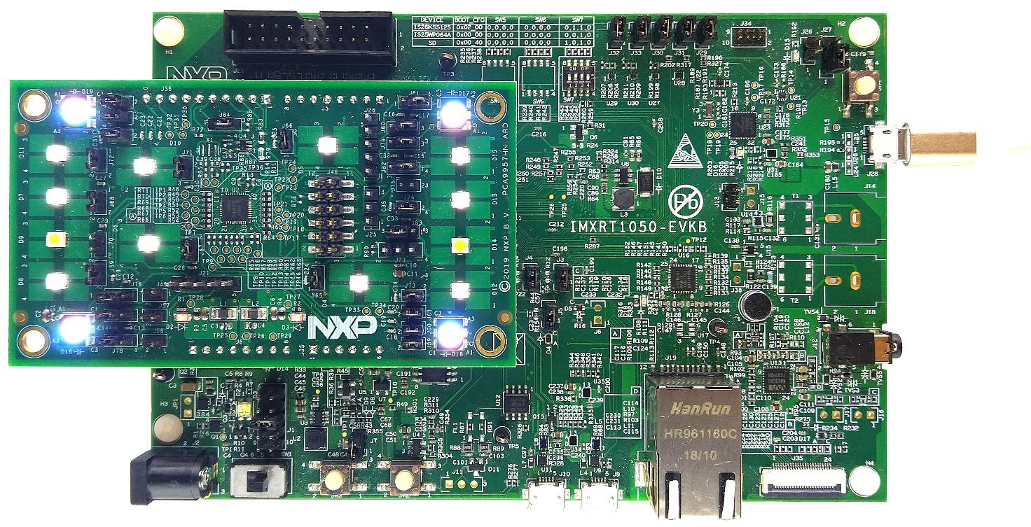
4.1 Using PCA9957HN-ARD with MIMXRT1050-EVK Board
Figure 1 shows the required hardware for operation of the PCA9957HN-ARD expansion board with MIMXRT1050-EVK.
- One MIMXRT1050-EVK board
- One PCA9957HN-ARD expansion board
- One USB-A / USB Micro-B cable
- PC with Windows 10 operating system
The MIMXRT1050-EVK mother board can be powered by one of the following three methods:
- Connecting an external 5 VDC power supply to the barrel power connector (
J2) on the board - Connecting a USB cable from the PC to the the Micro-B USB connector (
J9) on the board - Connecting a USB cable from the PC to the USB connector (
J28) on the board. When the PC is connected in this fashion, the USB port can simultaneously act as a debug interface. Therefore, by using a single USB cable connected toJ28, the EVK can be powered and at the same time linked to the PC for data exchange
Be aware that older USB ports (USB 1.1) on the PC might not be able to deliver the 500 mA current needed before
establishing communication. In this case, the user must use an external power supply (connected to J2).
From J1 on the EVK board (see Figure 1) the user can select the power configuration for the mother
board. For further details, download the IMXRT1050 EVK Board Hardware User Guide (MIMXRT1050EVKHUG.pdf) available at
i.MX RT1050 Evaluation Kit.
To configure the hardware and workstation, complete the following procedure:
- On the MIMXRT1050-EVK board, populate
R278,R279,R280,R281with zero-ohm resistors (0402 package) to link the SPI lines to the Arduino connector - Using jumper
J1, select the suitable power configuration for the EVK - To select USB
J28as the power supply, place a jumper in the 5–6 position on jumperJ1 - To select an external power supply connected to the barrel power connector
J2, place a jumper in position 1–2 on jumperJ1 - Insert the PCA9957HN-ARD daughter card on the Arduino port of the EVK (see Figure 1)
- Using USB connector
J28, connect the EVK board to a USB port on the computer - Install the IMXRT1050 target firmware (download from NXP site and see UM11581 for step-by-step instructions)
- Install GUI application on PC (see UM11581 , Arduino shields GUI and firmware installation manual)
- Open the GUI application to operate the device from the PC
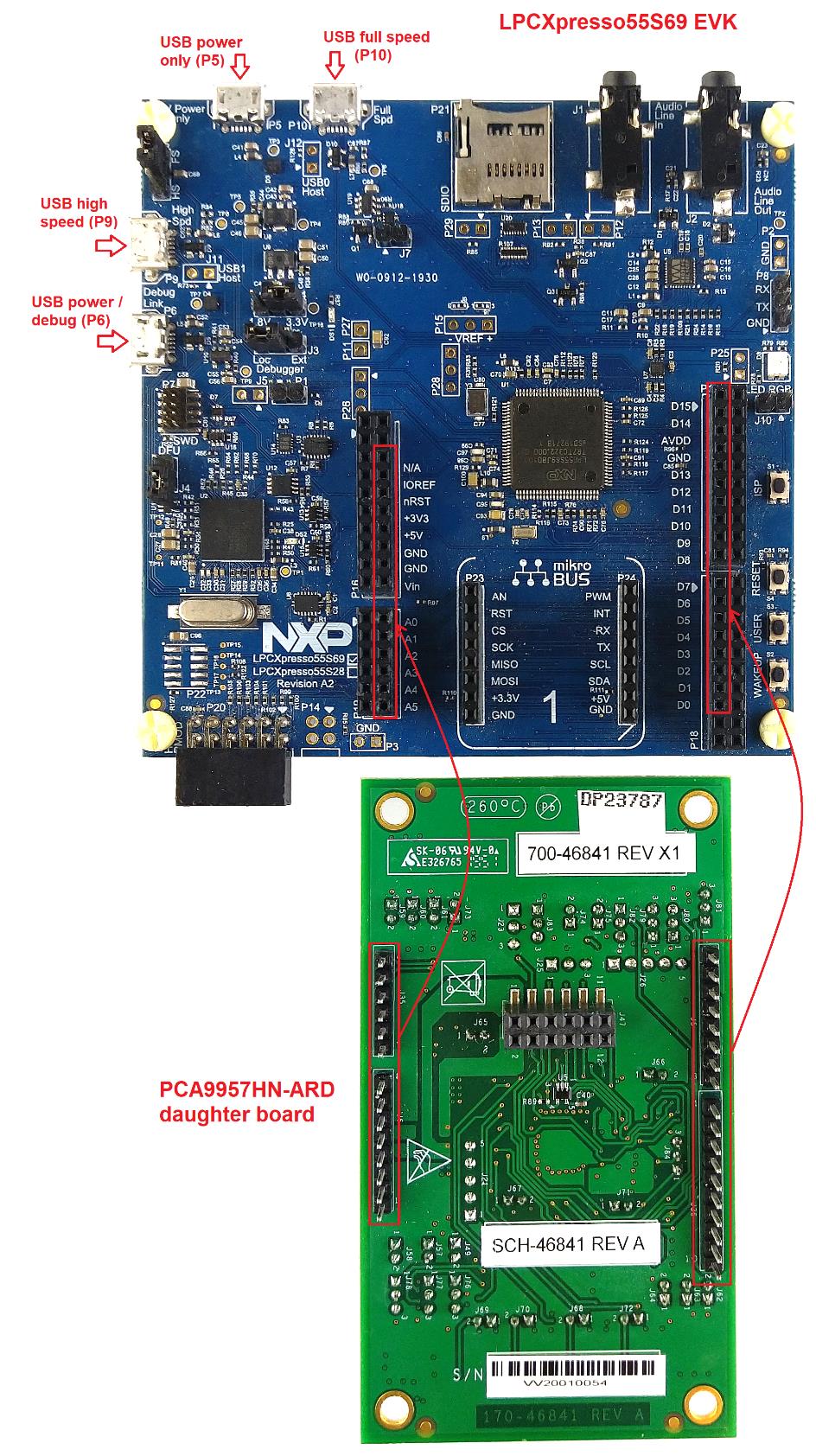
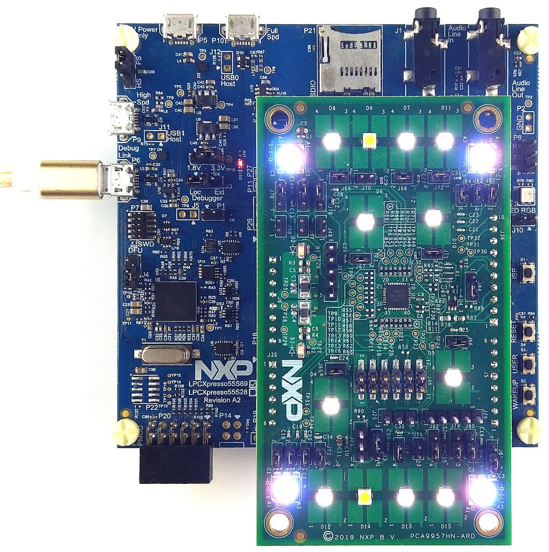
4.2 Using PCA9957HN-ARD with LPC55S69-EVK Board
Figure 3 shows the required hardware for operation of the PCA9957HN-ARD and LPC55S69-EVK board.
- One LPC55S69-EVK board
- One PCA9957HN-ARD expansion board
- One USB-A / USB Micro-B cable
- PC with Windows 10 operating system
The LPC55S69-EVK board is equipped with four USB Micro-B connectors: P5, P6,
P9 and P10. The board can be powered through any USB port. However, using the
P6 USB connector to connect the board to the PC simplifies the start-up operation because
P6 is designated for debugging and the USB cable thus accomplishes two tasks at the same time: powering
the board and serving as a data link between the EVK board and PC. For more details, see LPCXpresso55S69 Development Board.
To configure the hardware and workstation, complete the following procedure:
- Insert the PCA9957HN-ARD daughter card to
P16–P19connectors located on LPC55S69-EVK development board (see the marked pins ofP16–P19, Figure 3) - Connect the development board using port
P6USB port of PC - Install the LPCXpresso55S69 target firmware (download from NXP site and see UM11581 for step-by-step instructions)
- Install GUI application on PC (see UM11581 , Arduino shields GUI and firmware installation manual)
- Open the GUI application to operate the device from the PC
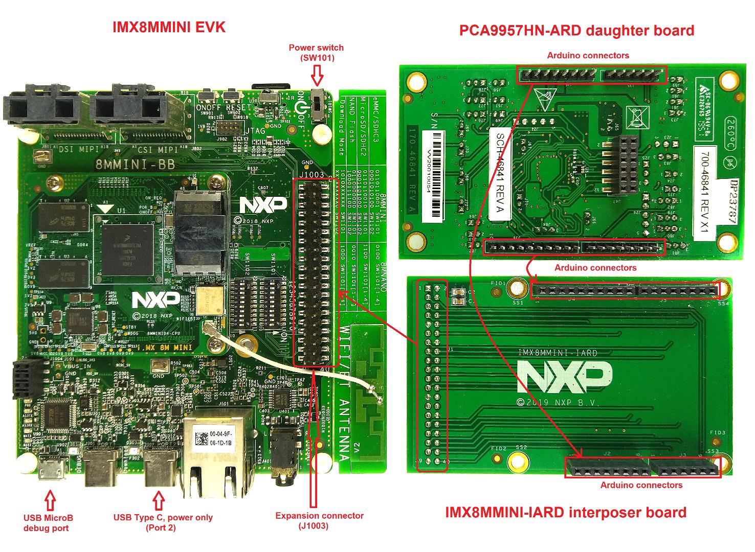
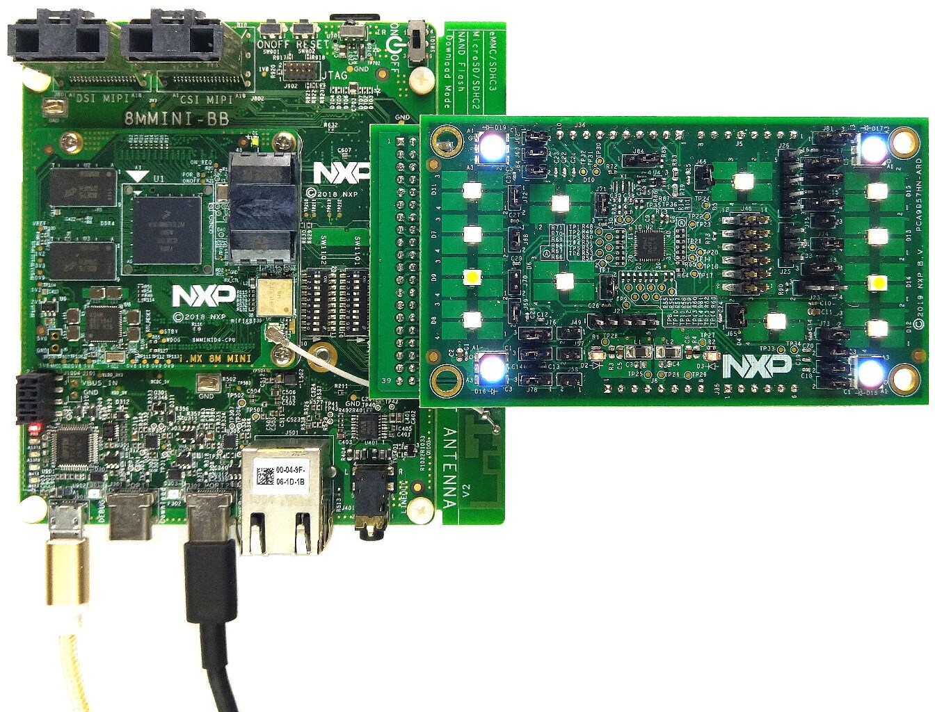
4.3 Using PCA9957HN-ARD with 8MMINILPD4-EVK Board
When 8MMINILPD4-EVK board is used with the PCA9957HN-ARD board, a specially designed EVK expansion board—the
IMX8MMINI-IARD board—must be mounted as an interposer between the 8MMINILPD4-EVK board and the PCA9557HNARD. This is
because the 8MMINILPD4-EVK uses a 2 x 20-pin expansion connector (J1003) instead of an Arduino
connector.
Connector J1003 on the 8MMINILPD4-EVK board is a multipurpose port containing digital I/O lines,
including specialized I²C and SPI buses. The IMX8MMINI-IARD pins on the PCA9957HD-ARD board and the 2 x
20 connector pins on the 8MMINILPD4-EVK board.
Figure 5 shows how these three boards are connected. This configuration consists of:
- One 8MMINILPD4-EVK board
- One PCA9957HN-ARD board
- One IMX8MMINI-IARD interposer board
- One USB-C cable
- One USB Micro-B cable
To power up and operate the setup. The USB-C cable for power must be connected to PORT 2 of the EVK board. The power
switch SW101 on the EVK board must be set to the On position to power up the setup. Data communication
is achieved by routing a USB Micro-B cable from a USB port on the PC to the debug port (J901) on the
EVK.
Attach the expansion board by plugging the PCA9957HN-ARD board into the Arduino connector of the IMX8MMINI-IARD
interposer and then plugging the IMX8MMINI-IARD interposer into the expansion connector (J1003) located
on the i.MX8MMINI EVK board. See Figure 5 for the location of all referenced connectors and switches.
For more details regarding the power-up and operation of the setup assembly, see 8MMINILPD4-EVK user manual and IMX8MMINI-IARD User Manual. The files can be downloaded from NXP site.
To configure the hardware and workstation, complete the following procedure:
- Insert the PCA9957HN-ARD onto the IMX8MMINI-IARD interposer board Arduino connectors (located on the top side)
- Attach IMX8MMINI-IARD connector
J1(located on the bottom of the board) intoJ1003expansion board located on the top side of 8MMINILPD4-EVK (see Figure 5) - Power up the EVK board using a USB Type C cable attached to Port 2
- Connect the EVK to the PC, using a USB Micro-B cable, attached to
J901debug port. - Place
SW101in On position to power up the boards - Install the MIMXRT1050 target firmware (download from NXP site and see UM11581 for step-by-step instructions)
- Install GUI application on PC
- Open the GUI application to operate the device from the PC
Design Resources
Support
Forums
Connect with other engineers and get expert advice on designing with the PCA9957HN-ARD on one of our community sites.