Getting Started with the RD33771CNTREVM
Contents of this document
-
Get Started
-
Know the Hardware
-
Configure Hardware
-
Install Software
Sign in to save your progress. Don't have an account? Create one.
Purchase your Flexible Battery Management System (BMS) Reference Design
1. Get Started
The NXP analog product development boards provide an easy-to-use platform for evaluating NXP products. The boards support a range of analog, mixed-signal and power solutions. They incorporate monolithic integrated circuits and system-in-package devices that use proven high-volume technology. NXP products offer longer battery life, a smaller form factor, reduced component counts, lower cost, and improved performance in powering state-of-the-art systems.
This page will guide you through learning about how to set up the RD33771CNTREVM board.
1.1 Kit Contents/Packing List
The RD33771CNTREVM contents include:
- Assembled and tested RD33771CNTREVM board in an anti-static bag
- High voltage cable with battery simulator board: BATTDEV-CON24
- Cable Assy, 22 AWG (red) L 200 mm, 8 pin W/1 crimp terminals
- Cable Assy, CAN twist L 500 mm, 3 pin W/2 crimp terminals
- Standoff, female/male, M3 x 20 mm nylon
- Fastener, nut, hex, nylon, M3
- Fastener, standoff M3 x 20 mm hex 5 mm male/female stainless
- Fastener, nut M3.5 hex SS machined
- Quick Start Guide
1.2 Additional Hardware
In addition to the kit contents, the following hardware is necessary or beneficial when working with this kit.
- Power supply 12 VDC with current capability 500 mA
- Power supply 10 to 50 VDC with current capability 500 mA or a 7-to-14-cell battery pack
- USB Multilink FX debug probe
1.3 Windows PC Workstation
This reference design requires a Windows PC workstation. Meeting these minimum specifications should produce great results when working with this reference design.
- Windows 10, Windows XP, Windows 7, or Vista in 32- or 64-bit version
2. Know the Hardware
2.1 Board Features
- Four BCCs on one board
- Each BCC can measure voltage for up to 14 battery cells with high accuracy
- Each BCC has 6-channel temperature sensing
- The first BCC has a current-sensing point, could connect an external shunt resistor for current measurement
- Capacitor or TPL isolation communication on the board
- TPL isolation for off-board communication
- Cell balancing current set to 100 mA, expandable up to 300 mA by adding CB resistors
- Low-cost SBC and MCU as BCC management
- One channel CAN interface
- JTAG debugging interface
- High EMC performance: passed BCI 200 mA, CE CISPR class 3
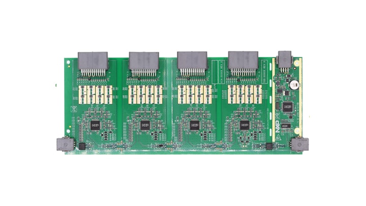
2.2 Board Description
The RD33771CNTREVM provides a solution for a centralized and distributed architecture for lithium-ion battery management in automotive applications. This board allocates four MC33771C devices controlled by one MCU. The MCU could be bypassed and stacked to a long daisy chain for a flexible BMS architecture.
Each BCC can measure lithium batteries having 7 to 14 cells each. The BCCs communicate by TPL daisy chain or capacitor isolation. The MCU is supplied by an SBC that is powered by a 12 VDC power source.
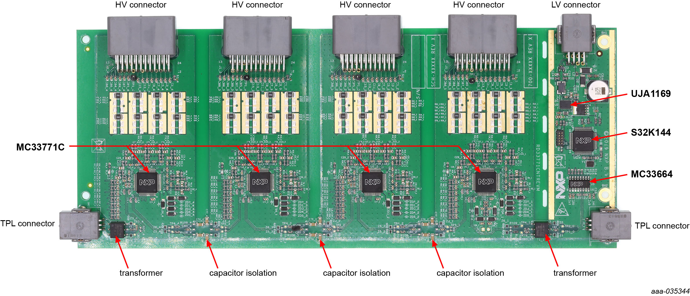
2.3 Board Components
Overview of the RD33771CNTREVM flexible HV BMS solution.
| Name | Description |
|---|---|
| MC33771C | 14-channel Li-ion battery cell controller IC. |
| MC33664 | Isolated communication IC. |
| UJA1169 | Mini high-speed CAN companion system basis chip. |
| S32K144 | 32-bit automotive general purpose microcontroller. |
| HM2103NL | TPL isolation transformer. |
| TPL connector | TPL communication connector. |
| HV connector | Battery sensing connector for real battery or battery simulation board. |
3. Configure Hardware
3.1 Configure the Hardware
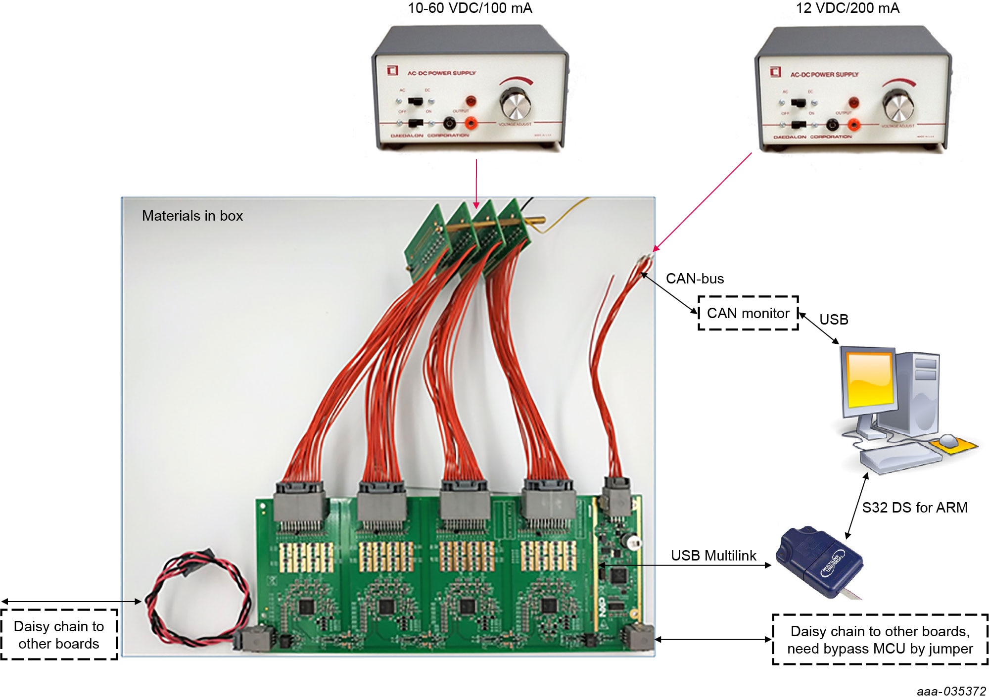
To configure the hardware, complete the following procedure:
- Plug battery simulator and low-voltage cables to the board
- Connect battery simulator cable to power supply #1 (10 to 60 VDC, current limitation 100 mA). The text labels on the bottom of the board indicate pin positions
- Connect the low-voltage cable to power supply #2 (12 VDC, current limitation 200 mA). The text labels on the bottom of the board indicate pin positions
- If successfully supplied, the LED on the board is lit up. The power consumption for power supply #1 is about 40 mA, and for power supply #2, the consumption is about 50 mA
- If no MCU program is downloaded or the MCU power is OFF, the LED on each BCC turns OFF after 60 seconds
- Connect multilink to the JTAG port next to the MCU
- Launch S32 Design Studio for ARM
- Import example software project, launch, and download/debug in S32 Design Studio for ARM to evaluate this board
Incorrect connections of the power and ground wires damage the board.
Incorrect connections of the power and ground wires damage the board.
4. Install Software
4.1 Installing the Software
- Download the S32 Design Studio IDE for ARM (Version 2018.R1 is recommended) Download S32DS for ARM
- Open the installer, then follow the instructions in the setup wizard
- Get the example project from RD33771CNTREVM webpage
- Start development with an example source code
4.2 Success
Start embedded application development.
Design Resources
Board Information
Additional Resources
In addition to our RD33771CNTREVM: Flexible Battery Management System (BMS) Reference Design page, you may also want to visit:
Product Pages
- MC33664: Isolated network high-speed transceiver
- MC33771C: 14-Channel Li-Ion Battery Cell Controller IC
- S32K: Scalable microcontrollers for automotive general purpose and high-reliability industrial
- UJA1169LTK: Mini high-speed CAN companion system basis chip
Tool Pages
- RD33771CNTREVM: Flexible Battery Management System (BMS) Reference Design. This page provides overview information, technical and functional specifications, ordering information, documentation, and software. The Getting Started provides quick-reference information applicable to using the RD33771CNTREVM reference design, including the downloadable assets
Application Pages
Hardware Pages
Software Pages
- Analog Expert Software and Tools
- S32DS-ARM: S32 Design Studio for Arm®