Power Delivery Board Quick Starts
Contents of this document
-
Out of the Box
-
Get Hardware
-
Configure Hardware
Sign in to save your progress. Don't have an account? Create one.
Purchase your HVBMS | Centralized Cell Monitoring Unit (CMU)
1. Out of the Box
The NXP analog product development boards provide an easy-to-use platform for evaluating NXP products. The boards support a range of analog, mixed-signal and power solutions. They incorporate monolithic integrated circuits and system-in-package devices that use proven high-volume technology. NXP products offer longer battery life, a smaller form factor, reduced component counts, lower cost and improved performance in powering state-of-the-art systems.
This page will guide the user through the process of setting up and using the RD33774PDSTEVB board.
1.1 Kit Contents and Packing List
- Assembled and tested evaluation board/module in antistatic bag
- Three cell terminal cables
- Transformer physical layer (TPL) cable
1.2 Additional Hardware
In addition to the kit contents, the following hardware is necessary or beneficial when working with this kit:
- A 4-cell to 18-cell battery pack or a battery pack emulator, such as BATT-18EMULATOR
- A TPL communication system. If a user-specific system is not available, the evaluation setup or the 800 V HVBMS reference design can be used
- The 800 V HVBMS reference design consists of the HVBMS battery management unit (RD-K358BMU) and the 800 V HVBMS battery junction box (RD772BJBTPL8EVB). For the 800 V HVBMS reference design, a graphical user interface (GUI) based on FreeMASTER is available
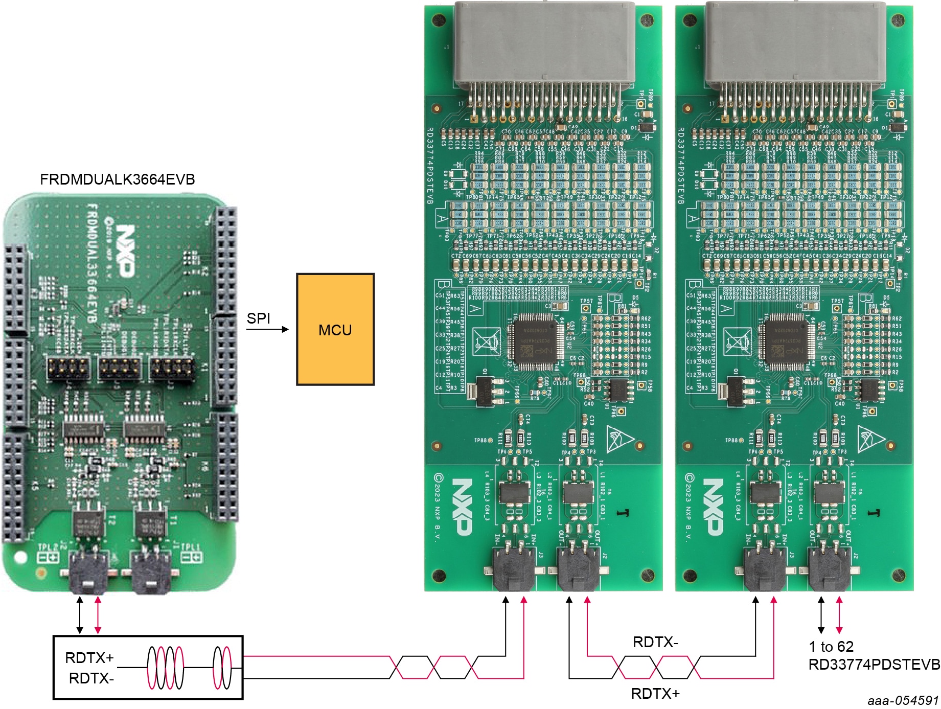
- The evaluation setup consists of the FRDMDUALK3364EVB (EVB for MC33664A) in combination with the S32K3X4EVB-T172 (S32K3X4 EVB)
- For the evaluation setup, a graphical user interface, EvalGUI 7, is available in Secure Files at this link: MC33775A Evaluation GUI V7
1.3 Minimum System Requirements
This evaluation board requires a Windows PC workstation.
- USB-enabled computer with Windows 7 or Windows 10
- FTDI USB serial port driver (for FT230X Basic UART device)
1.4 Software
Installing software is necessary to work with this evaluation board. All listed software is available (under NDA) on the evaluation board page RD33774PDSTEVB.
2. Get Hardware
2.1 Board Features
- Daisy-chain device connection
- LED indicator for operation mode
- Cell-balancing resistors (22 Ω per individual cell)
- Cell-sense input with RC filter
- GPIO: Digital I/O, wake-up inputs, convert trigger inputs, ratiometric analog inputs, analog inputs with absolute measurements
- INTB, RSTB, FS0B, LIMP0, FCCU pins
- EEPROM (connected to the IC with I²C interface) to store user-defined calibration parameters
2.2 Board Description
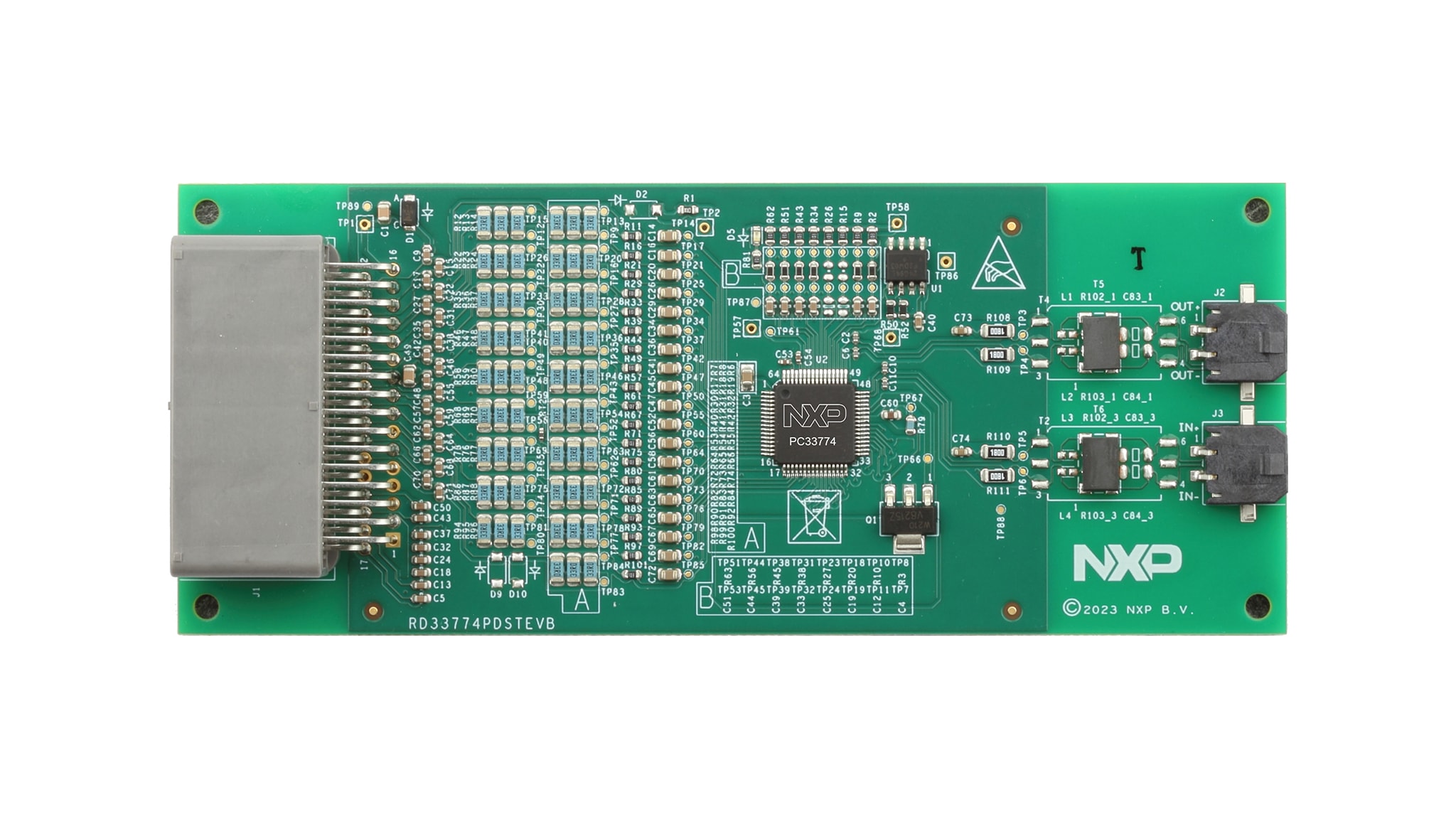
The RD33774PDSTEVB serves as a hardware evaluation tool in support of NXP's MC33774ATP device. The MC33774ATP is a battery-cell controller that monitors up to 18 lithium-ion battery cells. RD33774PDSTEVB is designed for use in automotive and industrial applications. The device performs analog-to-digital conversion on the differential cell voltages and currents. It is also capable of battery-charge coulomb counting and battery temperature measurements. The RD33774PDSTEVB can be used for rapid prototyping of MC33774ATP-based applications that involve voltage and temperature sensing.
2.3 Board Components
Overview of the RD33774PDSTEVB board
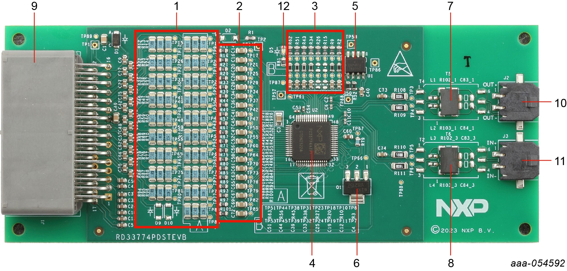
| Number | Name | Description |
|---|---|---|
| 1 | Cell balancing resistors | 3 x 33 ohms in parallel on each Cx pin: 200 mA of cell-balancing current @4.5 V |
| 2 | Cell terminal low-pass filters | LPF: 10 kΩ resistor/0.047 µF capacitor to GND |
| 3 | GPIO low-pass filters | For NTC connections and temperature measurement |
| 4 | MC33774ATP (U2) |
18-cell battery-cell controller IC |
| 5 | NV24C64DWVLT3G (U1) |
High-speed 64 Kb I²C EEPROM |
| 6 | NSS1C201MZ4T1G (Q1) |
NPN supply bipolar transistor |
| 7, 8 | TC102M or capacitive coupling | Default BOM: High-voltage single-channel transformers |
| 9 | JAE-MX34032NF2 (J1) |
32-pin connector for cell connections and NTC connections |
| 10 | MOLEX-43650-0213 (J2) |
TPL connector to higher node |
| 11 | MOLEX-43650-0213 (J3) |
TPL connector to lower node |
| 12 | LED | VAUX status |
3. Configure Hardware
This section gives guidance on how to set up and run the RD33774PDSTEVB evaluation board and GUI.
3.1 Battery Emulator Connection
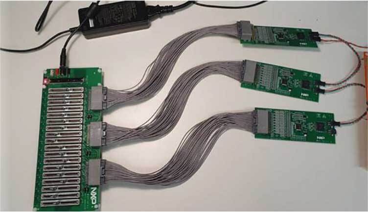
The RD33774PDSTEVB supports the use of a battery-cell emulator, such as the BATT-18EMULATOR board.
The BATT-18EMULATOR is an 18-cell battery-emulator board that provides a way to change the voltage across any of the 18 cells and four voltage outputs to emulate four external NTCs. The emulator board can be connected to the RD33774PDSTEVB J1 connector using the provided cell connection cable.
Up to three RD33774PDSTEVB can be connected to one BATT-18EMULATOR. See Figure 1
Design Resources
Board Information
Additional References
In addition to the MC33774, 18 Channel Li-Ion Battery Cell Controller IC ASIL D page, visit: